

Page 1
INSTRUCTION MANUAL
®
Tower
Hobbies®
guarantees
this kit to be
free from defects
in both material and
workmanship at the
WARRANTY
date of purchase. This
warranty does not cover any
component parts damaged by
use or modica tion. In no case shall
Tower Hobbies’ liability exceed the
original cost of the purchased kit. Further,
Tower Hobbies reserves the right to change
or modify this warranty without notice.
In that Tower Hobbies has no control over the nal
assembly or material used for nal assembly, no
liability shall be assumed nor accepted for any damage
or injury resulting from the use by the user of the nal
user-assembled product. By the act of using the user-assembled
product, the user accepts all resulting liability.
If the buyer is not prepared to accept the liability associated with the
use of this product, the buyer is advised to return this kit immediately in
new and unused condition to the place of purchase.
To make a warranty claim send the defective part or item to Hobby Services at
the address below: (Visit hobbyservices.com for more information.)
Hobby Services • 3002 N. Apollo Dr. Suite 1 • Champaign IL 61822 • USA
Include a letter stating your name, return shipping address, as much contact information as
possible (daytime telephone number, fax number, e-mail address), a detailed description of
the problem and a photocopy of the purchase receipt. Upon receipt of the package the problem
will be evaluated as quickly as possible.
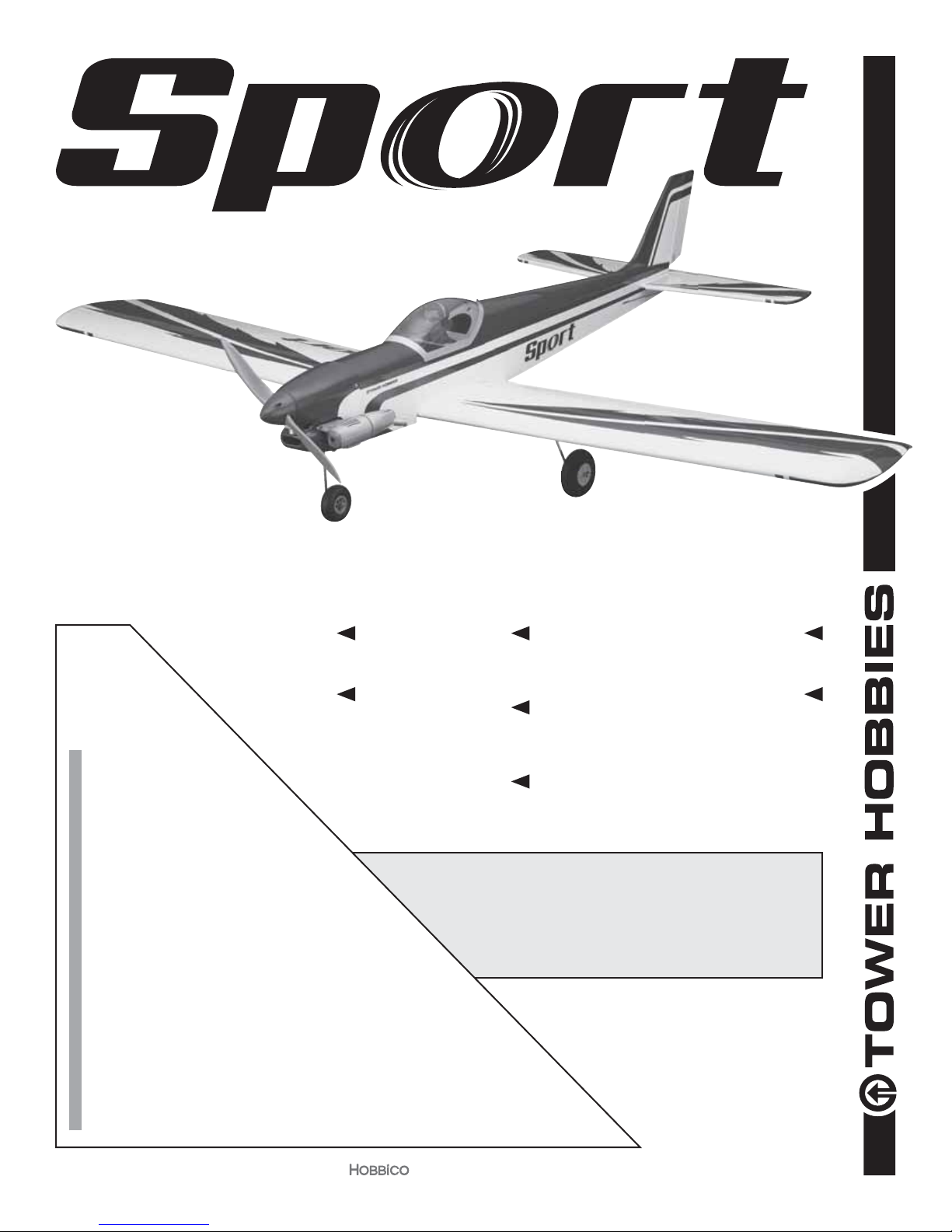
WINGSPAN
60.2 in [1529mm]
RADIO
4– 5 channel
4–5 servos
72 –76oz. [2041– 2155 g]
LENGTH
48.7 in [1237mm]
WING AREA
592.8 sq in [38.24 dm2]
WEIGHT
READ THROUGH THIS MANUAL
BEFORE STARTING CONSTRUCTION.
IT CONTAINS IMPORTANT INSTRUCTIONS
AND WARNINGS CONCERNING THE
ASSEMBLY AND USE OF THIS MODEL.
WING LOADING
17.49 – 18.46 oz /ft2 [53 –56 g/dm2]
POWER
.46 – .55 cu in [7.5 – 9.0cc] 2-stroke glow,
.70 cu in [11.5cc] 4-stroke glow,
Motor: 1.65" [42mm] 925W,
Castle Creations Edge Lite 75 ESC (not included)
ESC: 60A - 4S (not included)
TOWER HOBBIES
Champaign, Illinois
(217) 398-8970 ext. 6
airsupport@hobbico.com
®
®
© 2016 Tow er Ho bb ies.
A subsidiary of Hobbico, Inc.
TOWA2030
1
Page 2

TABLE OF CONTENTS
INTRODUCTION . . . . . . . . . . . . . . . . . . . . . . . . . . . . . . . . 2
ADDITIONAL ITEMS REQUIRED . . . . . . . . . . . . . . . . . . . 2
Radio/Servos . . . . . . . . . . . . . . . . . . . . . . . . . . . . . . . . 2
Glow Engine. . . . . . . . . . . . . . . . . . . . . . . . . . . . . . . . . 2
Brushless Electric Motor . . . . . . . . . . . . . . . . . . . . . . . 3
ADHESIVES, HARDWARE &
OTHER ACCESSORIES . . . . . . . . . . . . . . . . . . . . . . . 3
KIT INSPECTION. . . . . . . . . . . . . . . . . . . . . . . . . . . . . . . . 3
REPLACEMENT PARTS LIST. . . . . . . . . . . . . . . . . . . . . . 3
CONTENTS . . . . . . . . . . . . . . . . . . . . . . . . . . . . . . . . . . . . 4
PREPARATION . . . . . . . . . . . . . . . . . . . . . . . . . . . . . . . . . 4
ASSEMBLE THE WING. . . . . . . . . . . . . . . . . . . . . . . . . . . 5
Hook Up the Ailerons. . . . . . . . . . . . . . . . . . . . . . . . . . 5
Mount the Landing Gear . . . . . . . . . . . . . . . . . . . . . . . 6
Join the Wing Halves . . . . . . . . . . . . . . . . . . . . . . . . . . 6
ASSEMBLE THE FUSELAGE . . . . . . . . . . . . . . . . . . . . . . 7
Install the Pushrods and Mount the Nose Gear. . . . . . 8
Mount a Glow Engine . . . . . . . . . . . . . . . . . . . . . . . . 10
INTRODUCTION
Congratulations and thank you for purchasing the Tower
Hobbies Sport .46/EP ARF. After you’ve mastered the basics
with a high-wing trainer, the “Sport” is a great 1st low-wing
model, or an every day, all-around sport model for experienced
yers too!
For the latest technical updates or manual corrections, nd
the Sport .46/EP ARF on the Tower Hobbies web site at
towerhobbies.com. If there is new technical information or
changes to this model a “tech notice” box will appear on
the page.
ADDITIONAL ITEMS REQUIRED
Radio/Servos
A minimum of 4-channels is required to y the Sport .46/EP
ARF. The Tactic TTX650 is recommended because of its simple,
exible computer programming and multiple model memory:
❍ Tactic TTX650 6-channel programmable radio
(TACJ2650)
❍ Tactic TR625 6-channel receiver (TACJ0625)
❍ Hobbico 2S 6.6V 1300mAh LiFe battery
(HCAM6411)*
❍ On-off receiver switch (TACM2000)*
Servos nowadays are smaller and stronger, so we’ve designed
the servo mounts in the Sport to accommodate mini servos,
but full-size servos may still be used simply by enlarging the
opening in the servo mounts with a hobby knife. Four or 5
channels are required depending on whether you connect
the aileron servos to separate channels and mix them with
programmable mixing in your transmitter, or if you use a
Y-harness to connect the aileron servos to the same channel.
Install the Fuel Tank . . . . . . . . . . . . . . . . . . . . . . . . . . 11
Assemble the EP Motor Mount Box . . . . . . . . . . . . . 12
Mount the Brushless Motor . . . . . . . . . . . . . . . . . . . . 13
Cut the Cowl . . . . . . . . . . . . . . . . . . . . . . . . . . . . . . . 14
Mount the Cowl . . . . . . . . . . . . . . . . . . . . . . . . . . . . . 17
Install the Radio . . . . . . . . . . . . . . . . . . . . . . . . . . . . . 19
PREPARE THE MODEL FOR FLIGHT . . . . . . . . . . . . . . 19
Set the Control Throws . . . . . . . . . . . . . . . . . . . . . . . 19
Check the C.G. . . . . . . . . . . . . . . . . . . . . . . . . . . . . . 20
Balance the Model Laterally . . . . . . . . . . . . . . . . . . . 21
PREFLIGHT . . . . . . . . . . . . . . . . . . . . . . . . . . . . . . . . . . . 21
Engine/Motor Safety Precautions . . . . . . . . . . . . . . . 21
Battery Precautions . . . . . . . . . . . . . . . . . . . . . . . . . . 22
Range Check . . . . . . . . . . . . . . . . . . . . . . . . . . . . . . . 23
AMA SAFETY CODE (excerpts) . . . . . . . . . . . . . . . . . . . 23
General. . . . . . . . . . . . . . . . . . . . . . . . . . . . . . . . . . . . 23
Radio Control. . . . . . . . . . . . . . . . . . . . . . . . . . . . . . . 23
FLYING. . . . . . . . . . . . . . . . . . . . . . . . . . . . . . . . . . . . . . . 23
❍ Tactic TSX25 mini digital high-speed 2 ball bearing
servo (TACM0225)
❍ Tactic TSX20 mini high-speed 2 ball bearing servo
(TACM0220)
OR
❍ Tactic TSX35 standard sport servo (TACM0235)
❍ (2) 12" [300mm] universal servo extensions
(TACM2130)
If mixing the aileron servos electronically with programmable
mixing in the transmitter:
❍ (2) 6" [150mm] universal servo extensions
(TACM2092)
If connecting the servos with a Y-harness:
❍ Futaba dual servo extension (FUTM4130)
*If powering your Sport .46/EP with a brushless electric motor
the BEC in the ESC may be used to power your receiver and
servos, so no receiver battery or on/off receiver switch will
be required. If using servos or an ESC different than those
recommended in the instruction manual, be certain the servos
do not overload the BEC or voltage regulator.
Glow Engine
The Sport is suited for a .45 - .55 2-stroke or .70 4-stroke. The
O.S. Max .46AXII (OSMG0548) is illustrated in this manual.
Other Accessories for a Glow Engine
❍ 1/4" [6.4mm] R/C foam rubber (HCAQ1000)
❍ Great Planes Dead Center Hole Locator (GPMR8130)
❍ 4-40 (DUBR0505) or 3mm (DUBR0560) tap and drill
set (see step 6, page 10)
❍ Suitable propeller for your engine
2
Page 3
Brushless Electric Motor
The electric setup for the Sport is straightforward: a Great
Planes Electri y RimFire .32 on a 13 x 8 E prop with a minimum
60A ESC powered by a 4S battery in the 3300mAh – 4000 mAh
range. A Castle Creations Edge Lite 75 was selected and is
illustrated in the instruction manual because it is compact,
easily programmable and features data logging.
❍ 42-50-800 RimFire .32 (GPMG4700)
❍ APC 13 x 8 thin E prop (APCQ3080)
❍ Castle Creations Edge Lite 75 (CSEM1200)
❍ FPWP2234 FlightPower 4S 3300mAh 25C
❍ FPWP2404 FlightPower 4S 4000mAh 25C
❍ 3/16" heat shrink tubing (GPMM1056)
❍ T-style Star connector (HCAM4001)
If your servos draw more current than the BEC in your ESC
is rated for, one option is to use a voltage regulator with a
higher Amp rating that draws power from the 4S LiPo motor
battery. The Castle Creations 10A BEC is suitable (CSEM0005).
Another option is to use a receiver battery.
LiPo Battery Charger
To charge a 4S 4000mAh LiPo at 1C, a charger capable of
at least 70 Watts is required (4S x 4.2V/cell = 16.8V x 4A =
67 Watts). The Triton EQ2 (GPMM3156) is more than enough
charger with 100W output AC and 120W output DC.
ADHESIVES, HARDWARE AND
OTHER ACCESSORIES
Other than common hobby tools here is a list of the rest of
the items required:
❍ 30-minute epoxy (GPMR6043)
❍ Epoxy brushes (GPMR8060)
❍ Mixing cups (GPMR8056)
❍ Mixing sticks (GPMR8055)
❍ Threadlocker thread locking cement (GPMR6060)
❍ Thin CA (GPMR6001)
❍ Medium CA (GPMR6007)
❍ CA applicator tips (HCAR3780)
❍ CA accelerator (GPMR6035)
A covering iron with a cover sock may be required for tightening
and re-bonding covering to the model that may have loosened
between the time the plane was manufactured and the time
the model was removed from the box. The 21st Century iron
is preferred because of its long cord, contoured shoe and
precisely adjustable temperature range:
❍ Coverite 21
❍ Coverite 21st Century Cover Sock (COVR2702)
st
Century Sealing Iron (COVR2700)
KIT INSPECTION
Before starting to build, take an inventory of this kit to make
sure it is complete, and inspect the parts to make sure
they are of acceptable quality. If any parts are missing or
are not of acceptable quality, or if you need assistance
with assembly, contact Product Support. When reporting
defective or missing parts, use the part names exactly as
they are written in the Kit Contents list.
Tower Hobbies Product Support
3002 N. Apollo Drive, Suite 1 Ph: (217) 398-8970, ext. 6
Champaign, IL 61822 Fax: (217) 398-7721
E-mail: airsupport@hobbico.com
REPLACEMENT PARTS LIST
Order No. Description
TOWA4070
TOWA4071
TOWA4072
TOWA4073
TOWA4074
TOWA4075
TOWA4076
TOWA4077
TOWA4078
TOWA4079
TOWA4080
Wing Set
Fuselage
Tail Surface Set
Cowl
Hatch/Canopy
Landing Gear Set
EP Motor Mount Parts Set
10-24 x 2 Nylon Wing Bolts ( 2 pcs. )
2" Spinner
Fuel Tank 260cc
Decals
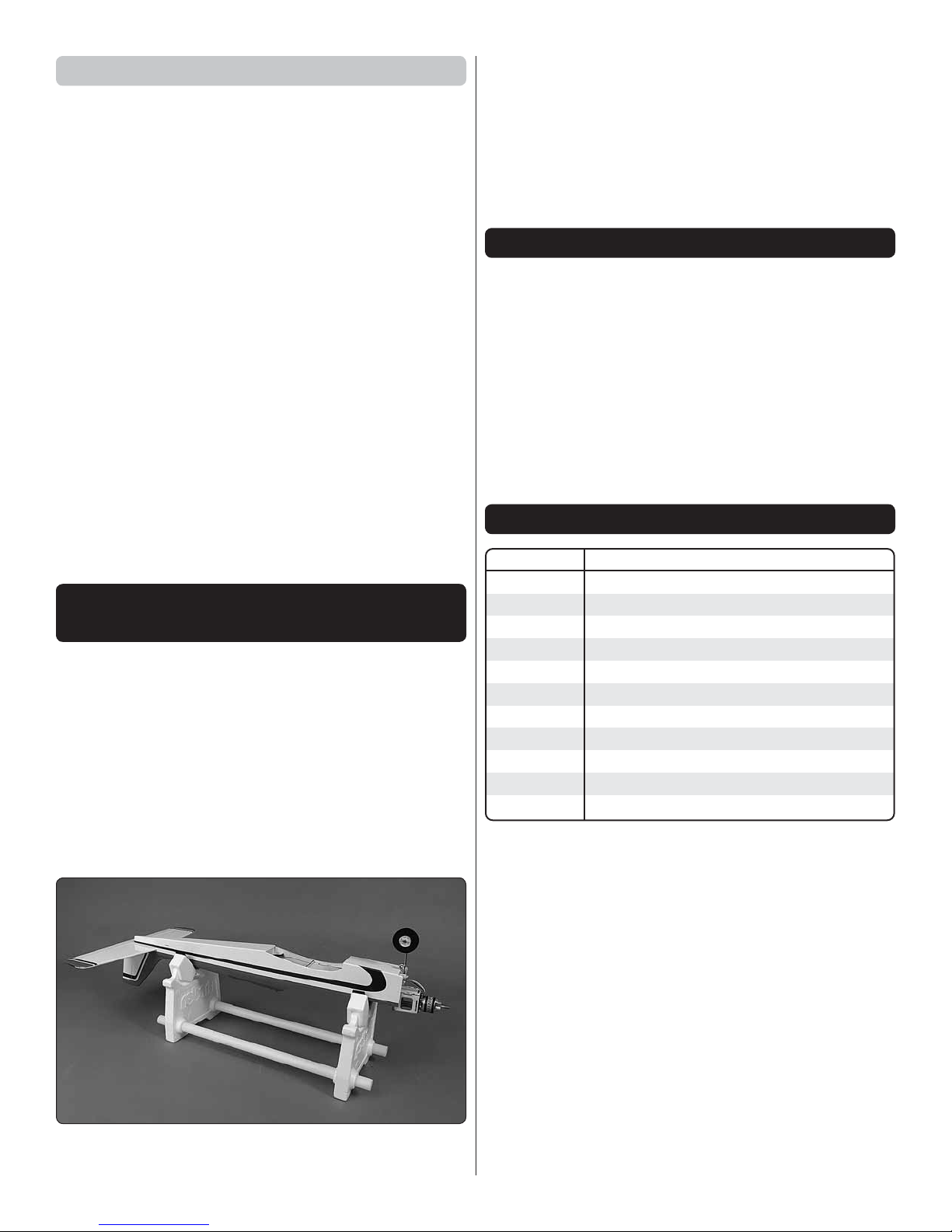
A Robart Super Stand II (ROBP1402) is also indispensable
for working on your Sport.
3
Page 4
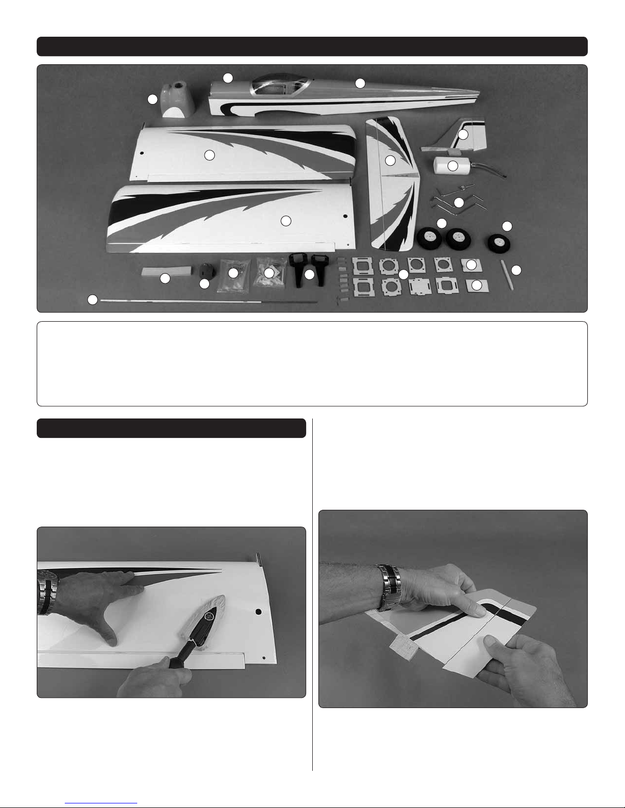
CONTENTS
16
1. Cowl
2. Canopy Hatch
3. Fuselage
4. Wing
5. Horizontal Stabilizer
6. Vertical Stabilizer
2
1
4
11
12
7. Fuel Tank
8. Landing Gear Wires
9. 75mm Main Wheels
10. 65mm Nose Wheel
11. Wing Joiner
12. 2” Spinner
3
6
5
4
13
14
15
17
13. Metal Hardware
14. Nylon Hardware
7
8
9
18
10
20
19
19. Pilot Mount Plate
20. Balsa Stick
15. L& R Engine Mount
16. Pushrods
17. EP Motor Mount Box
18. Hatch Cover
PREPARATION
NOTE: The covering on your Sport requires less heat than
you may be used to if you’re already familiar with iron-on
coverings – too much heat causes seams and edges to
pull and draw away from each other causing wavy, uneven
edges or exposed balsa. Follow the instructions below
to tighten the covering on your model.
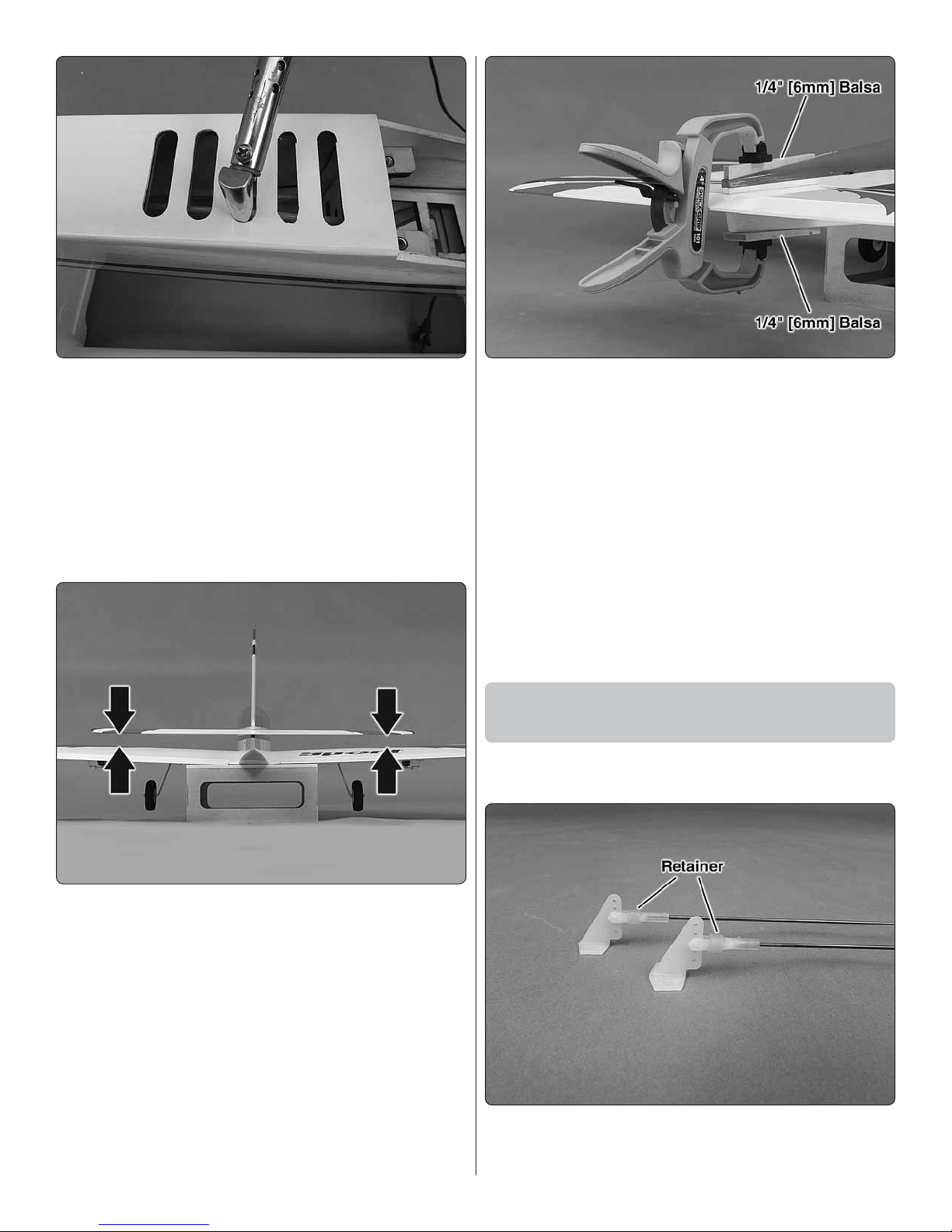
1. Use a covering iron with a cover sock to tighten any loose
❏
covering and thoroughly bond it to the wood structure. The
optimum temperature measured on the surface of a covering
iron with a protective cover sock is about 280ºF [140ºC] which
requires a dial setting of about 300ºF [150º C] or “medium”
heat on most covering irons. Wherever the covering is over
wood (especially on the sheet balsa tail surfaces) press down
on the iron to thoroughly bond the covering to the balsa
underneath. If the covering blisters up over balsa and cannot
be pressed back down, the iron may be too hot or you are
leaving it in one location for too long—try reducing the heat
or moving the iron a little faster.
2. Give a generous tug on all control surfaces to check the
❏
hinges. Add thin CA where necessary to any loose hinges.
Residual CA or CA “fog” is removable with a paper towel
square dampened with CA debonder.
4
Page 5

3. If powering your Sport with a glow engine, apply a lm
Cut out
1/16" [1.5 mm]
Servo Arm
90º Connector
❏
of epoxy or CA to edges of the covering around the nose
and rewall to seal from fuel and exhaust residue. It would
also be a good idea to use an epoxy brush to fuelproof the
back of the rewall and the fuel tank area as well.
ASSEMBLE THE WING
Do the left wing rst…
2. If necessary, enlarge the servo cutout to t your servo.
❏
3. Use the string to pull the aileron servo wire through the
❏
wing and t the servo into the servo openings.
Hook Up the Ailerons
1. Attach a 12" [300mm] servo extension to each aileron
❏
servo. Use 1/2" [13mm] heat shrink tubing, tape or a dab of
glue to secure the connections.
4. Drill 1/16" [1.6mm] holes for the servo mounting screws
❏
in the wing and in the aileron for the control horn screws (use
care not to drill through the top of the aileron).
5. Enlarge the holes in the servo arm with a #50 [.070"]
❏
drill. Mount the servo and horn, make the pushrod and
hook up the aileron using the hardware shown for servo
arms for pushrods.
Refer to this image while mounting the aileron servos
and hooking up the ailerons.
6. After mounting the aileron horns, remove the screws,
❏
harden the holes with a few drops of thin CA, allow to harden,
and then reinstall the screws.
7. Install the aileron servo and linkage in the right wing
❏
the same way.
5
Page 6

Mount the Landing Gear
Landing gear
angled back.
3. Use two at landing gear straps as a guide to drill 3/32"
❏
[2.4mm] holes into the landing gear block in the left wing.
4. Enlarge the holes in the two landing gear straps with
❏
a 1/8" [3.2mm] drill.
1. Use a metal le to grind a at spot in the back of one
❏
of the main landing gear wires. Note: The landing gear wires
angle back toward the wing trailing edge.
5. Mount the main landing gear to the rail in the wing with
❏
two straps and four M3 x 10 screws. Trim the slots as needed
so the wires t ush.
6. Mount the other landing gear and wheel to the other
❏
wing the same way.
Join the Wing Halves
2. Mount a 3" [75mm] main wheel to the landing gear
❏
wire with two wheel collars and two M3 x 5 Phillips screws
and threadlocker.
1. Test- t both wing halves together with the nylon alignment
❏
pin and the hardwood wing joiner. Make any adjustments for
a good t.
6
Page 7

2. Stack two or three paper towels over each other and
❏
cut them into small squares. Have the paper towel squares
and denatured alcohol ready for epoxy clean up while joining
the wing in the next few steps.
4. Use plenty of masking tape to tightly clamp the wing
❏
halves together and use a small clamp to clamp the front
of the wing together at the leading edge tab. Use the paper
towel squares dampened with denatured alcohol to wipe
away excess epoxy as you proceed. Allow the epoxy to fully
harden before removing the clamps and tape.
5. Residual tape adhesive may be cleaned with naptha
❏
(lighter uid). Areas of the covering that may have lifted
from removing the tape should be retightened with your
covering iron.
3. Mix approximately 1-1/2 to 2 oz. of 30-minute epoxy.
❏
Working quickly, pour some epoxy into the spar cavities in
both wings and distribute with a wire or small dowel. Coat
one end of the joiner and insert it into one of the wing halves.
Coat the protruding end of the joiner and both ends of both
wing halves. Insert the nylon alignment pin and join the wing
half, removing excess epoxy as it squeezes out.
ASSEMBLE THE FUSELAGE
1. If you haven’t yet done so, use a covering iron with a
❏
cover sock to tighten the covering over the fuselage and
horizontal and vertical stabilizer.
7
Page 8
2. If powering your Sport with a brushless motor, cut the
❏
covering from the air exit vents in the bottom of the fuselage.
For a better nish, cut the covering about 1/32" [1mm] inside
the edges of each opening and use a trim iron with a rounded
tip to seal the covering neatly down around the edges.
3. Mount the wing to the fuselage with two 10-24 x 2"
❏
[50mm] nylon wing bolts (for convenience, you may shorten
the wing bolts by cutting off up to 5/8" [15mm]).
4. Test t the horizontal and vertical stabilizers (stab and
❏
n) into the fuselage.
6. Remove the stab and n and prepare for gluing into
❏
the fuselage. Typically, the n and stab are glued into the
fuselage together. An alternate method is to glue in the stab
rst, clamping the n fairing to the top of the stab with 1/4"
[6mm] balsa (not included) for a perfectly tight glue joint. If
done this way, be certain to temporarily position the n to
center the stab laterally. After the epoxy has hardened glue
in the n.
If gluing in the stab and n together, apply 30-minute epoxy to
all joining areas, t them into position and wipe away excess
epoxy before it hardens. If any weight was required to level
the stab don’t forget to reposition the weight and doublecheck the alignment before the epoxy hardens.
7. After the epoxy gluing the stab and n to the fuselage
❏
has hardened remove the wing.
Install the Pushrods and
Mount the Nose Gear
1. Cut two of the long wire pushrods including the threaded
❏
end to a length of 27" [685mm].
5. View the model from behind and check the alignment
❏
of the stab to the wing. If necessary, adjust the slot in the
fuselage to get the stab horizontally aligned with the wing—
in most cases, all that will be required is a small amount of
weight on the high side of the stab. If necessary, the stab
saddle can be sanded slightly to get the stab to align.
2. Prepare the two pushrods as shown with control horns,
❏
clevises and silicone tube retainers.
8
Page 9

Hinge Line Hinge Line
CORRECT INCORRECT
5. If installing a brushless motor, cut the rest of the way
❏
through the partially cut air inlet in the rewall and remove
the piece as shown in the photo in the following step.
6. Cut the threaded end off another pushrod to a length of
❏
16" [400mm]. Make an “L” bend in one end of the pushrod
and insert it into the guide tube for the nose steering.
3. Slide one of the pushrods into the elevator tube in the
❏
fuselage. Position the horn on the elevator as shown in the
sketch, then mark and drill 5/64" [2.5mm] holes through the
elevator for the horn mounting screws. Mount the horn with
two M2 x 14 Phillips machine-thread screws and the back
plate on the top of the elevator – don’t over tighten the screws
so much that you squish the balsa.
4. Install the other pushrod and mount the horn to the
❏
rudder the same way.
7. Assemble the nose gear as shown with the hardware
❏
indicated– use threadlocker on the screws.
8. Fit the steering arm onto the pushrod and mount the
❏
nose gear to the rewall with four M3 x 12 Phillips machine
screws and M3 at washers and lock washers.
9. Rotate the nose gear from side-to-side to check for free
❏
movement. If necessary, make a slight bend in the nose gear
pushrod to ease movement.
9
Page 10

Mount a Glow Engine
If installing a brushless motor, skip to Assemble the EP
Motor Mount Box on page 12.
The engine illustrated in the instruction manual is mounted
inverted. This is the easiest, most-convenient and moststreamlined way to mount the engine, but the exhaust is
aimed directly at the wing. This presents no problems, but
you should have plenty of paper towels and cleaner on-hand
to wipe off exhaust residue after each ight. The engine could
also be mounted upright, but much of the cowl will have to
be cut away for the engine, and exhaust will still be deposited
on the fuselage.
4. Slide the engine forward or back so the drive washer
❏
(or the back plate of your spinner) will be 4-1/2" [115mm]
from the rewall.
1. If mounting your engine inverted as shown, drill a 3/16"
❏
[4.8mm] hole through the rewall at the “+” mark in the left
side of the fuselage (the same side of the fuselage as the
throttle arm on the carburetor on the engine). If mounting your
engine upright, drill the hole through the “+” mark through
the rewall on the right side of the fuselage.
2. Temporarily fasten the engine mount halves to the
❏
rewall with four M3 x 25 Phillips machine-thread screws,
M3 lock washes and at washers, but do not fully tighten
the screws yet.
3. Place your engine on the mount. Adjust the width of
❏
the mount halves to t your engine, then temporarily tighten
the screws.
5. Use a Great Planes Dead-Center Hole Locator or similar
❏
tool to mark the engine mount screw holes onto the engine
mount. Remove the engine mount from the rewall.
6. Decide what size screws you want to use to hold your
❏
engine to the mount. M3 x 12 Phillips machine-thread screws
are supplied, but will require a M3 tap. If you already have
a 4-40 tap, then 4-40 x 5/8" screws (not supplied) may be
used instead. If using the supplied M3 x 12 screws, drill
2.4mm [.096" (#41)] holes through the marks made in the
mount for the mounting screws. If using 4-40 screws, drill
#43 or 3/32" holes through the marks made in the mount for
the mounting screws.
10
Page 11

7. Tap the threads into the holes—this may be easily and
❏
quickly done with a drill.
8. Mount the engine mount to the rewall and mount the
❏
engine to the mount.
Install the Fuel Tank
1. Loosen the screw in the stopper in the fuel tank and
❏
take out the stopper/fuel line assembly. Check to make sure
the clunks are present and secure on the lines and that the
vent tube is pointed up toward the top of the tank. Also make
sure the lines on the clunks are not so long that the clunks
can contact the back of the tank (and possibly become stuck).
Make any adjustments necessary, then reassemble the tank
making sure to securely tighten the screw to expand the
stopper to seal the tank.
9. Cut the 17-3/4" [450mm] pushrod guide tube to a length
❏
of 11-1/2" [290mm]. Guide the tube through the hole you
drilled in the rewall down through the holes in the formers
for the throttle pushrod guide tube.
10. Cut the unthreaded end off another pushrod to a length
❏
of 16-1/2" [420mm]. Thread a clevis onto the threaded end.
Bend the front of the pushrod as necessary to connect to the
carburetor arm on the engine and install the pushrod. We’ll
hook up the other end to the throttle servo after the servo
is installed later.
2. Make a fuel tank strap from a 6-1/2" [165mm] piece of
❏
the rougher, “hook” side and a 6-1/2" [165mm] piece of the
softer, “loop” side of the included hook-and-loop material.
Join the strips with 2" [50mm] of overlap to complete the
fuel tank strap.
3. Make another fuel tank strap same as the rst.
❏
11
Page 12

5. Cut one of the fuel lines (from either of the two tubes
❏
on the bottom of the tank) to the correct length to t the
carburetor. Leave the other two lines (one for fueling/defueling,
the other for the pressure/vent line from the muf er) the length
they are now – we’ll cut them later after the cowl has been
cut and tted.
Proceed to Cut the Cowl on page 14. EP Version
Assemble the EP Motor Mount Box
4. Cut a 2-1/4" x 4-1/2" [55 x 115mm] sheet from a piece
❏
of 1/4" [6mm] RC foam rubber to cushion the bottom of the
fuel tank. Install the fuel tank straps under and up through
the slots in both sides of the fuel tank oor, place the foam
rubber sheet, install the tank with the lines through the hole
in the rewall, and then tightly strap the tank into place.
NOTE: There is a hatch in the fuel tank oor through which
nose weight or the receiver battery may be installed. For now,
cover the hatch with the included lite-ply cover and install
the fuel tank. Later, if it is determined that nose ballast is
required, the tank may be removed for access to the hatch.
1. Glue together two pieces of the front and back of the EP
❏
motor mount box with the arrows pointing up and the holes
and edges in each half aligned with each other.
2. Place the front of the motor mount box on your workbench
❏
with the back (the surface with the tabs) facing upward as
shown. Press M3 blind nuts into the back.
12
Page 13

3. Before using any glue, test t the sides, top, bottom,
❏
front and back of the motor mount box together. Make sure
the arrows on the front and back point toward the top of the
mount box and that the arrow on the bottom of the mount
box points toward the front of the box.
5. Glue the triangle reinforcements around the back and
❏
front—use medium CA and stick them into place with a hobby
knife. Reinforce all glue joints where necessary.
6. Round the top, forward corners of the motor mount box
❏
to clear the cowl as shown.
Mount the Brushless Motor
4. Holding the assembly together, use medium CA to glue
❏
the box together. Use care not to get any CA on your ngers.
Do not build up large glue llets until after the next step.
1. Mount the motor mount box to the rewall with four
❏
M3 x 12 Phillips machine screws, M3 at washers, M3 lock
washers and threadlocker.
13
Page 14

2. Assemble the “X” mount and the propeller shaft to
❏
your motor. Mount the motor mount box with four M3 x 12
Phillips machine screws and M3 at washers, lock washers
and threadlocker.
Cut the Cowl
A No. 569 or 570 Dremel grout
removal bit and a sanding
drum are indispensable for
easily and accurately cutting
a berglass cowl. Always wear
eye and breathing protection
when cutting berglass.
3. Connect the ESC to the motor and mount it to the bottom
❏
of the motor mount box. For the Castle Creations Edge Lite
75 ESC we soldered the female bullet connectors that came
with the motor to the three motor wires (protected with 3/16"
heat shrink tubing) and a Star connector to the battery wires.
Then we mounted the ESC to the box with a piece of foam
rubber and nylon ties.
4. Power up the ESC with the receiver and transmitter
❏
and run the motor to make sure it turns the correct direction.
If the motor turns the wrong direction, swap any two of the
three motor wires (or reverse the motor direction in the ESC
programming if available).
1. If you have a glow engine installed, temporarily remove
❏
the engine to position the cowl for marking the location of
the slot for the nose gear. Fit the cowl, then mark the slot.
2. Use the grout cutter or similar bit to cut the slot about
❏
3/4" [20mm] deep. Test t the cowl to make sure the slot is
wide enough and deep enough to t the cowl.
5. Cut the 1/4" x 1/4" x 4" [6 x 6 x 100mm] balsa stick
❏
into two pieces and glue them across the back of the rewall
as shown.
14
Page 15

3. Cut an inlet opening in the air scoop at the bottom of the
❏
cowl. If using a brushless motor, it may also be necessary to
enlarge the opening in the front for the prop adapter. Start with
your grout cutter, then smooth the edges with a drum sander.
4. If using a brushless motor the cowl should require no
❏
further cutting. If using a glow engine, mount the engine
back onto the engine mount. Cover any access point into
the engine where berglass dust could enter such as the
carburetor and exhaust.
5. There’s no really fast, easy way to cut holes in a cowl
❏
that ts tightly around an engine like this. The best way is to
install the cowl and, little by little, mark, cut and re t the cowl
as necessary until it will go on over the engine. We started
by using a pencil to mark the inside of the cowl where it
interfered with the sides of the carburetor.
6. Use your Dremel to cut the rst holes.
❏
15
Page 16

7. Continue to t, mark and cut the cowl until you can
❏
get it to t.
8. Once you can get the cowl to t all the way over the
❏
engine, mark and cut the hole for the muf er. This cowl was
cut so that the muf er has to be installed after the cowl
(tightening the muf er bolts through holes cut in the opposite
side of the cowl), but another way is to cut all the way to the
back of the cowl so it can be slipped past the muf er after
it has been mounted to the engine.
16
Page 17

9. Cut any other holes necessary for the nose gear, fueling
❏
line, muf er pressure line, glow plug igniter, etc.
11. Here’s a close-up of the nished cowl.
❏
Mount the Cowl
Now that the cowl can be positioned all the way over the
engine and muf er, it may be mounted to the fuselage.
1. Use a straightedge and a ne-point, felt-tip pen to mark
❏
the middle of the rewall down both sides of the fuselage.
The ink lines can be removed later with denatured alcohol,
but if you still prefer not to mark directly on the covering you
can mark over strips of tape.
10. Once all the holes are cut and the cowl will t over
❏
the engine and muf er, use 320-grit sandpaper to sand the
edges of the cutouts smooth and even.
2. Mark another line down both sides of the fuselage 2"
❏
[50mm] aft of the rst line. (We marked these lines over
masking tape so they would be easier to see over the
blue trim.)
17
Page 18

3. If necessary, enlarge the hole in the back plate of the
❏
spinner to t the crank shaft or propeller shaft, then t the
back plate onto the engine/motor. Temporarily mount a
prop to securely hold the back plate into place. (There is a
sandpaper disc included that may be used to help lock the
back plate to the motor or the prop to the back plate if either
turns while tightening the propeller.)
4. Position the canopy hatch onto the fuselage.
❏
6. Once the screw hole locations have been marked,
❏
double-check to be sure the cowl is positioned to align with the
spinner, then drill the rst cowl screw hole with a 1/16" [1.6m]
drill. Enlarge the hole in the cowl only with a 3/32" [2.4mm]
drill, then insert the rst M2.5 x 8 washer-head wood screw.
7. Remembering to switch over to the smaller drill each
❏
time a hole is drilled into the fuselage, one-at-a-time drill the
hole, enlarge the hole in the cowl only, then insert another
screw until all four screws are in.
5. Insert cardboard or balsa spacers the thickness of
❏
your preferred spinner gap (approximately 3/32" [2.5mm])
between the front of the cowl and the back plate. Tape the
cowl into place, or have an assistant hold the cowl centered
on the back plate. Mark the screw holes on the sides of the
cowl 2" [50mm] ahead of the lines on the fuselage—the top
screws should be about 5/8" [16mm] down from the top of
the fuselage and the bottom screws should be about 5/8"
[16mm] up from the bottom of the fuselage.
8. Remove the prop and cowl. Add a few drops of thin CA
❏
to each screw hole. Allow the CA to fully harden, then mount
the cowl, prop and spinner.
18
Page 19

Install the Radio
1. If necessary, enlarge the cutout in the servo tray to
❏
t your servos. Then install the servos in the tray, but don’t
screw them down yet.
2. Cut the unused arms from your servo arms and place
❏
them on your servos. Center the servos and control surfaces.
Mark the elevator and rudder pushrods where they cross the
holes in the servo arms.
6. Cut the nose steering pushrod to the correct length and
❏
bend it as necessary to connect the rudder servo. Connect
the pushrod to the servo arm using a screw-lock connector,
an M3 set screw and a retainer.
7. Install the throttle servo (if used) and use another
❏
screw-lock connector to connect the throttle pushrod to
the throttle servo.
8. Now that all the pushrods are connected, drill 1/16"
❏
[1.6mm] holes in the servo tray for the servo screws. Mount
the servos with the screws that came with them.
Refer to this photo while completing servo hookup.
3. Disconnect the clevises from the horns on the elevator
❏
and rudder and remove the pushrods from the fuselage. Make
a 90-degree bend in each pushrod at the marks. Fit each
pushrod to a servo arm, install a 90-degree pushrod keeper
and cut off the excess wire.
4. Remove the clevises from the back of the pushrods so
❏
they can be reinstalled into the guide tubes in the fuselage.
Install the pushrods and thread the clevises back on.
5. Adjust the length of the pushrods as necessary by
❏
threading the clevises in or out, then reinstall the servo arms
onto the servos.
9. Mount the receiver and receiver battery (if used) with
❏
remaining hook-and-loop strap and R/C foam rubber. Mount
an on/off switch (also if used). The image in this step is for a
glow setup. For a brushless motor setup, the receiver may
be mounted to the servo tray over the location for the glow
throttle servo or to the side of the fuselage in the same area.
10. Plug a Y-harness or servo extensions into your receiver
❏
to connect to the ailerons through the bottom of the fuselage
for connecting to the servo leads from the wing.
PREPARE THE MODEL FOR FLIGHT
Set the Control Throws
CAUTION: If you have installed a brushless motor, remove
the propeller before turning on the radio and checking the
throws on the workbench.
In addition to the C.G., the control throws also have a major
effect on how the model ies and whether or not your rst ight
will be successful. Do not skip this important step and make
sure the throws are within the speci ed range. If necessary
use programming in your transmitter and/or change the
locations of the pushrods in the servo arms and/or control
horns to adjust the throw.
19
Page 20

1. It’s probably easiest to check and set the control
57mm
83mm
2-1/4"
3-1/4"
The recommended C.G. is 2-1/4"− 3-1/4"
[57mm −83 mm] back from the leading edge
of the wing.
❏
throws with the wing mounted on the fuselage. Mount the
wing. Check and set the control throws according to the
measurements below:
These are the recommended control surface throws:
HIGHLOW
ELEVATOR
Up & Down
RUDDER
Right & Left
AILERONS
Up & Down
2. Adjust the control throws as necessary by using the
❏
programming in your transmitter and/or reconnecting the
pushrods to holes farther out or farther in on your servo arms
and/or the control horns.
3. Once you have the nose wheel centered and the
❏
carburetor arm working properly, tighten the set screws in
the screw-lock connectors with threadlocker.
3/8"
[10mm]
14°
3/4"
[19mm]
21°
3/8"
[10mm]
19°
1/2"
[13mm]
18°
1"
[25mm]
27°
1/2"
[13mm]
24°
Check the C.G.
Same as the control throws, the C.G. has a great effect on how
the model ies. If the C.G. is too far forward the model may
be too stable and unresponsive to control inputs. If the C.G.
is too far aft the model may be too responsive and instable.
1. The model should be completely ready to y with all
❏
components installed (and an empty fuel tank if using a
glow engine). If you’ve installed a brushless motor, leave the
battery out of the plane, but keep it handy for positioning on
the bottom of the fuselage to determine where the battery
should be mounted inside.
2. If you’ve installed a brushless motor, reinstall the propeller
❏
and spinner.
3. Use a Great Planes C.G. Machine to balance the model
❏
according to the measurements speci ed, or mark the balance
range on the top of the wing and lift the model upside-down
with your ngertips. If you’ve installed a brushless motor
position the battery on the bottom of the fuselage to get the
model to balance.
As long as the model balances anywhere within the speci ed
range it is acceptable (but less-experienced pilots should
perform rst ights with the Sport balanced in the middle or
forward half of the range (slightly nose heavy).
4. If the Sport doesn’t balance where speci ed, move the
❏
receiver battery or motor LiPo battery or add stick-on lead
ballast to the nose or tail to achieve the correct C.G.
5. If you’ve made any adjustments by adding ballast or
❏
moving components check the C.G. again before ying.
20
Page 21

6. If using a brushless motor, once you’ve determined
❏
where to install the battery, apply the strip of the rougher,
hook-side of the included adhesive-back hook-and-loop strip
to the battery tray in the fuselage. Make a battery strap from
the included hook-and-loop strap material and install the
strap through the cutouts nearest the middle of the battery.
Balance the Model Laterally
1. Lift the Sport several times by the propeller shaft and
❏
the tail to see if one wing drops.
2. If one wing drops consistently, add weight to the opposite
❏
tip by sticking it to the outside or strategically concealing
it inside the balsa tip. An airplane that has been laterally
balanced will track better in ight and maintain its heading
better during maneuvers when the plane is climbing.
● Keep these items away from the prop: loose clothing, shirt
sleeves, ties, scarfs, long hair or loose objects such as
pencils or screwdrivers that may fall out of shirt or jacket
pockets into the prop.
● Use a “chicken stick” or electric starter to start the engine.
Do not use your ngers to ip the propeller. Make certain
the glow plug clip or connector is secure so that it will not
pop off or otherwise get into the running propeller.
● Make all engine adjustments from behind the rotating
propeller.
● The engine gets hot! Do not touch it during or right after
operation. Make sure fuel lines are in good condition so
fuel will not leak onto a hot engine, causing a re.
● To stop a glow engine, cut off the fuel supply by closing
off the fuel line or following the engine manufacturer’s
recommendations. Do not use hands, ngers or any other
body part to try to stop the engine. To stop a gasoline
powered engine an on/off switch should be connected to
the engine coil. Do not throw anything into the propeller
of a running engine.
WARNING: For brushless electric motors, never have the
motor battery connected to the ESC without the transmitter
turned on – after each ight (or any time after running the
motor) always disconnect the battery before turning off
the transmitter. And when ready to y (or whenever running
the motor for any reason), always turn on the transmitter
rst before connecting the motor battery.
Also make certain your failsafe is programmed for throttle
to 0% so in the event the receiver loses signal the motor
will not turn. Follow the instructions that came with your
radio control system to check and set the failsafe.
PREFLIGHT
Engine/Motor Safety Precautions
Failure to follow these safety precautions may result in
severe injury to yourself and others.
● Keep all engine fuel in a safe place, away from high heat,
sparks or ames, as fuel is very ammable. Do not smoke
near the engine or fuel; and remember that engine exhaust
gives off a great deal of deadly carbon monoxide. Therefore
do not run the engine in a closed room or garage.
● Get help from an experienced pilot when learning to operate
engines.
● Use safety glasses when starting or running engines.
● Do not run the engine in an area of loose gravel or sand;
the propeller may throw such material in your face or eyes.
● Keep your face and body as well as all spectators away
from the plane of rotation of the propeller as you start and
run the engine.
The recommended RimFire .32 is rated for 50A constant
current and 80A surge current. Powered by a 4S LiPo on
an APC 13 x 8E it draws about 58A static and momentary,
maximum peaks of about 50 – 55A in the air, but averages a
little less than 20A through a “normal” ight. This is a suitable
propeller choice and ies the Sport well—it can be zoomed
around in the sky, or cruise at lower throttle settings for more
scale-appearing ight.
Typical ight time may be as low as 4 minutes or even over
8 minutes depending on how aggressive and active you are
with the throttle – more power means shorter ight times.
Always unplug and remove the battery after your ight.
21
Page 22

In any case, use a ight timer initially set to a conservative
This is a SERIES battery adapter
that connects two batteries in series.
(3-Cell) 3200 mAh
(2-Cell) 3200 mAh
11.1V
7. 4 V
These are two 3200mAh batteries (one 11.1V and the
other 7.4V). When joined in SERIES, the result will be a
18.5V, 3200 mAh battery.
This is a PARALLEL battery adapter that
connects two batteries in parallel.
(3-Cell) 1500 mAh
(3-Cell) 1500 mAh
11.1V
11.1V
These two 1500mAh batteries (both 11.1V) are being
joined in PARALLEL. The result will be one 11.1V, 3000mAh
battery.
time (4 minutes for example). When the timer sounds, land.
Use a LiPo checker to measure the resting (unloaded) voltage
when you land. The voltage should not be below 3.75V/cell.
When you charge the battery also note how much capacity
it took to recharge (indicating how much was used for the
ight). Strive to use no more than 80% of the battery’s capacity.
Adjust your timer according to the voltage and capacity used
for the ight.
You can also use the worksheet on page 24 to determine
optimum ight times based on your ying style and battery
capacity.
Before mounting the motor and setting up the ESC and
battery, read the following important battery precautions:
IMPORTANT: If using multiple battery packs that are
connected with an adapter, never charge the batteries
together through the adapter. Always charge each
battery pack separately. Charge the batteries, then read
the following precautions on how to connect multiple
packs for ying the model:
Battery Precautions:
There are two ways to connect multiple battery packs: In
Series and in Parallel.
CAUTION: Never run the motor on the ground for more
than a few seconds. Otherwise, you may overload the
motor, battery or ESC.
Charge and store LiPo batteries in a safe place!
Never leave charging LiPo batteries unattended!
Battery Precautions
1. Connecting batteries in “Series” means to connect the
+’s to the –’s and the –’s to the +’s. This combines the
batteries’ Voltages, but the capacity remains the same.
2. Connecting batteries in “Parallel” means to connect
the +’s to the +’s and the -’s to the -’s. This combines the
batteries’ capacities, but the Voltage remains the same.
22
Page 23

PARALLEL
adapter
(2-Cell)
(3-Cell)
11.1V
7. 4 V
NEVER connect battery packs with different Voltages in
(3-Cell) 3200mAh
11.1V
(3-Cell) 1250mAh
11.1V
SERIES
adapter
Parallel–only combine in Series. Otherwise, the batteries
will try to “equalize” with the larger one trying to “charge”
the smaller one, thus causing heat and likely a re.
Also NEVER connect battery packs with different capacities in Series or in Parallel.
airport operator. I will give right-of-way and avoid ying in the
proximity of full-scale aircraft. Where necessary, an observer
shall be utilized to supervise ying to avoid having models
y in the proximity of full-scale aircraft.
3) Where established, I will abide by the safety rules for the
ying site I use, and I will not willfully and deliberately y my
models in a careless, reckless and/or dangerous manner.
5) I will not y my model unless it is identi ed with my name
and address or AMA number, on or in the model. Note: This
does not apply to models while being own indoors.
7) I will not operate models with pyrotechnics (any device that
explodes, burns, or propels a projectile of any kind).
Radio Control
1) I will have completed a successful radio equipment ground
check before the rst ight of a new or repaired model.
2) I will not y my model aircraft in the presence of spectators
until I become a qualified flier, unless assisted by an
experienced helper.
3) At all ying sites a straight or curved line(s) must be
established in front of which all ying takes place with the
other side for spectators. Only personnel involved with ying
the aircraft are allowed at or in the front of the ight line.
Intentional ying behind the ight line is prohibited.
4) I will operate my model using only radio control frequencies
currently allowed by the Federal Communications Commission.
5) I will not knowingly operate my model within three miles
of any pre-existing ying site except in accordance with
the frequency sharing agreement listed [in the complete
AMA Safety Code].
9) Under no circumstances may a pilot or other person touch
a powered model in ight; nor should any part of the model
other than the landing gear, intentionally touch the ground,
except while landing.
Range Check
Don’t forget to perform your usual ground range checks as
written in the instruction manual that came with your radio
system to be certain it is operating correctly.
AMA SAFETY CODE (excerpts)
Read and abide by the following excerpts from the Academy
of Model Aeronautics Safety Code. For the complete Safety
Code refer to Model Aviation magazine, the AMA web site
or the Code that came with your AMA license.
General
1) I will not y my model aircraft in sanctioned events, air shows,
or model ying demonstrations until it has been proven to be
airworthy by having been previously, successfully ight tested.
2) I will not y my model aircraft higher than approximately
400 feet within 3 miles of an airport without notifying the
FLYING
There are no particular ight characteristics about the Sport
that you need to be made aware of ahead of time. If you
prefer ying on high-rates most of the time, it will be easier
to takeoff with the rudder on low rates so the nose wheel
will not be too responsive. Once airborne, you can switch
the rudder to high rates.
The Sport is a well-balanced, neutral, easy- ying plane that
exhibits no bad tendencies and will go wherever you point it.
Simply y the Sport within your capabilities and take it easy
for the rst couple of ights to give yourself time to become
acclimated to it.
Have a ball! But always stay in control
and y in a safe manner.
GOOD LUCK AND GREAT FLYING!
23
Page 24

A
FORMULAS
BCDEFG
B / A D x .8 E / C B/1000 / (A /60)
1
2
3
4
5
6
7
8
9
10
Flight Time
(.10 ths )
Recharge
Capacity
mAh/minute
Battery
Capacity
Target Capacity
to Use in Flight
Recommended
Flight Time
Avg. In-Flight
Current
®
© 2016 Tow er Ho bb ies.
A subsidiary of Hobbico, Inc.
TOWA2030
 Loading...