

Page 1
INSTRUCTION MANUAL
®
Tower
Hobbies®
guarantees
this kit to be
free from defects
in both material and
workmanship at the
WARRANT Y
date of purchase. This
warranty does not cover any
component parts damaged by
use or modification. In no case
shall Tower Hobbies’ liability exceed
the original cost of the purchased kit.
Further, Tower Hobbies reserves the right to
change or modify this warranty without notice.
In that Tower Hobbies has no control over the final
assembly or material used for final assembly, no
liability shall be assumed nor accepted for any damage
resulting from the use by the user of the final
user-assembled product. By the act of using the
user-assembled product, the user accepts all resulting liability.
If the buyer is not prepared to accept the liability associated with the
use of this product, the buyer is advised to return this kit immediately in
new and unused condition to the place of purchase.
To make a warranty claim send the defective part or item to Hobby Services at
the address below:
Hobby Services • 3002 N. Apollo Dr. Suite 1 • Champaign IL 61822 • USA
Include a letter stating your name, return shipping address, as much contact information
as possible (daytime telephone number, fax number, e-mail address), a detailed description
of the problem and a photocopy of the purchase receipt. Upon receipt of the package the
problem will be evaluated as quickly as possible.
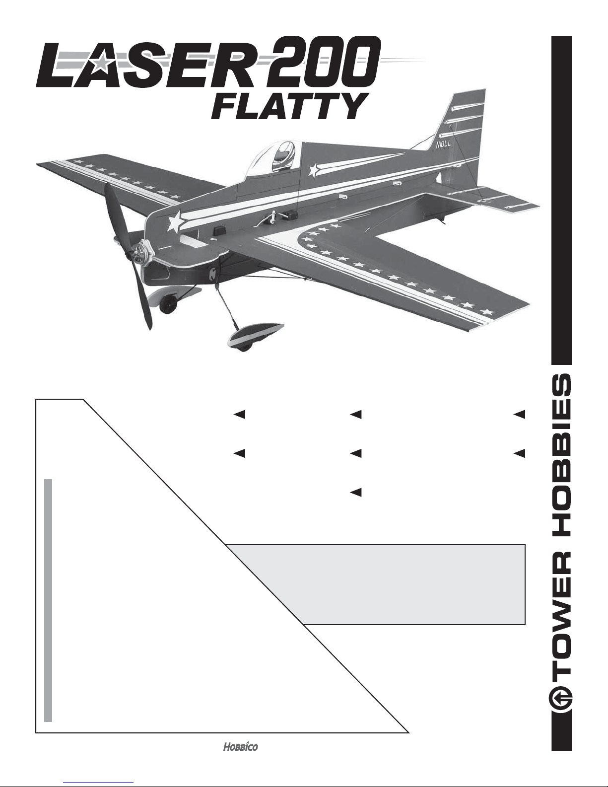
WINGSPAN
33.5 in [850 mm]
RADIO
4 channel
LENGTH
33 in [840 mm]
WING AREA
261 in2 [16.8 dm2]
WEIGHT
5.6 – 6.4 oz [160–180 g]
READ THROUGH THIS MANUAL
BEFORE STARTING CONSTRUCTION.
IT CONTAINS IMPORTANT INSTRUCTIONS
AND WARNINGS CONCERNING THE
ASSEMBLY AND USE OF THIS MODEL.
WING LOADING
3.1– 3.5 oz/ft2 [9–11 g/dm2]
MOTOR
RimFire™ 250,
2S or 3S 350 mAh LiPo,
8A–10 A ESC, 8x3.8 APC Prop
TOWER HOBBIES
Champaign, Illinois
(217) 398-8970 ext. 5
airsupport@hobbico.com
®
®
© 2015 Tower Hobbies .
A subsidiary of Hobbico, Inc.
TOWA2005
Page 2
TABLE OF CONTENTS
INTRODUCTION . . . . . . . . . . . . . . . . . . . . . . . . . . . . . . . . 2
AMA . . . . . . . . . . . . . . . . . . . . . . . . . . . . . . . . . . . . . . . 2
SAFETY PRECAUTIONS . . . . . . . . . . . . . . . . . . . . . . . . . 2
REQUIRED FOR COMPLETION. . . . . . . . . . . . . . . . . . . . 2
Radio Equipment and Accessories . . . . . . . . . . . . . . . 2
Tools and Adhesives . . . . . . . . . . . . . . . . . . . . . . . . . . 3
KIT INSPECTION . . . . . . . . . . . . . . . . . . . . . . . . . . . . . . . 3
KIT CONTENTS. . . . . . . . . . . . . . . . . . . . . . . . . . . . . . . . . 3
ASSEMBLY . . . . . . . . . . . . . . . . . . . . . . . . . . . . . . . . . . . . 4
Assemble the Bottom Half . . . . . . . . . . . . . . . . . . . . . . 4
Assemble the Top Half. . . . . . . . . . . . . . . . . . . . . . . . . 8
INTRODUCTION
Thank you for purchasing the Tower Hobbies Laser 200 ARF.
The Laser bridges the gap between heavier, durable “fl at
foamies” intended for 3D fl ight with a 3S battery and the
feather-weight, delicate types intended for slow, precision
fl ight on 2S. If 3D is your game, the Laser still features the
ingredients of a typical 3S airframe, but has been lightened
and simplifi ed to also fl y well on 2S. So, whichever is your
preference let’s get started!
For the latest technical updates or manual corrections to the
Laser, go to www.towerhobbies.com/products/towa2005.html
and click on the Tech Notes button. If there is new technical
information or changes to this model a “tech notice” box will
appear in the upper left corner of the page.
Academy of Model Aeronautics
If you are not already a member of the AMA, please join! The
AMA is the governing body of model aviation and membership
provides liability insurance coverage, protects modelers’ rights
and interests and is required to fl y at most R/C sites.
Academy of Model Aeronautics
5151 East Memorial Drive
Muncie, IN 47302-9252
Tele. (800) 435-9262
Fax (765) 741-0057
Or via the Internet at: http://www.modelaircraft.org
IMPORTANT!!! Two of the most important things you can
do to preserve the radio controlled aircraft hobby are to avoid
fl ying near full-scale aircraft and avoid fl ying near or over
groups of people.
SAFETY PRECAUTIONS
Protect Your Model, Yourself & Others…
Follow These Important Safety Precautions
Hook up the Ailerons . . . . . . . . . . . . . . . . . . . . . . . . . . 9
Hook up the Elevator and Rudder . . . . . . . . . . . . . . . 12
Final Assembly. . . . . . . . . . . . . . . . . . . . . . . . . . . . . . 13
GET THE MODEL READY TO FLY. . . . . . . . . . . . . . . . . 14
Check the C.G. . . . . . . . . . . . . . . . . . . . . . . . . . . . . . 14
Check the Control Directions. . . . . . . . . . . . . . . . . . . 14
Set the Control Throws . . . . . . . . . . . . . . . . . . . . . . . 14
Identify Your Model . . . . . . . . . . . . . . . . . . . . . . . . . . 15
Ground Check . . . . . . . . . . . . . . . . . . . . . . . . . . . . . . 15
Flying . . . . . . . . . . . . . . . . . . . . . . . . . . . . . . . . . . . . . 15
Laser, if not assembled and operated correctly, could possibly
cause injury to yourself or spectators and damage to property.
2. You must assemble the Laser according to the instructions.
Do not alter or modify the model, as doing so may result in an
unsafe or unfl yable model. In a few cases the instructions may
differ slightly from the photos. In those instances the written
instructions should be considered as correct.
3. You must use an R/C radio system that is in good condition.
All components must be correctly installed so that the model
operates correctly on the ground and in the air. You must
check the operation of the model and all components before
every fl ight.
4. If you are not an experienced pilot or have not fl own this type
of model before, we recommend that you get the assistance
of an experienced pilot in your R/C club for your fi rst fl ights.
If you’re not a member of a club, your local hobby shop has
information about clubs in your area whose membership
includes experienced pilots.
5. While this kit has been fl ight tested to exceed normal
use, if the plane will be used for extremely high stress fl ying,
such as racing, or if a motor or battery larger than ones in
the recommended range is used, the modeler is responsible
for taking steps to reinforce the high stress points and/or
substituting hardware more suitable for the increased stress.
We, as the kit manufacturer, provide you with a top quality,
thoroughly tested kit and instructions, but ultimately the
quality and fl yability of your fi nished model depends on how
you build it; therefore, we cannot in any way guarantee the
performance of your completed model, and no representations are expressed or implied as to the performance or
safety of your completed model.
REMEMBER: Take your time and follow the instructions
to end up with a well-built model.
REQUIRED FOR COMPLETION
Radio Equipment and Accessories
1. Your Laser should not be considered a toy, but rather a
sophisticated, working model that functions very much like a
full-size airplane. Because of its performance capabilities, the
The radio required to fl y your Laser is standard and straight-
forward: A 4-channel radio system is required with a micro
receiver and micro servos. You may have to decide whether
2
Page 3
you are going to fl y your Laser on a 2S (7.4V) or 3S (11.7V)
battery—of course it can be fl own with both. Powered by a
2S battery the Laser is lighter and will fl y slower, precision
maneuvers better. Powered by a 3S battery the Laser will
fl y 3D maneuvers better. Following is the list of components
the Laser was designed to fi t. Any other gear with similar
specifi cations will be suitable, but slight modifi cations may
be required.
❍ RimFire 250 Outrunner motor (GPMG4502)
❍ Futaba R6004FF micro receiver (FUTL7624)
❍ (3) Futaba S3154 digital micro servos (FUTM0654)
OR
❍ (3) Futaba S3114 micro servos (FUTM0414)
Suitable batteries:
❍ FlightPower 2S 350mAh LiPo (FPWP2032)
and/or
❍ FlightPower 3S 350mAh LiPo (FPWP2033)
❍ FlightPower 10A brushless ESC (FPWM0210)*
-and- Deans® micro connector (WSDM3007)
OR
❍ Great Planes Silver Series 12A Brushless ESC
(GPMM1810)
❍ LiPo battery charger (GPMM3155)
❍ Charge Lead (GPMM3149)
❍ APC 8 x 3.8 propeller (APCQ5000)
It is also recommended that you stock up on spare propeller
saver O-rings (GPMG1405)
*The FlightPower ESC comes with a JST battery connector
while the FP batteries come with a Deans Micro connector,
so the battery connector on the ESC must be converted to
Deans to fi t the battery (WSDM3007). If a fl ight-ready ESC
that doesn’t require soldering connectors is preferred, the
Great Planes SS-12 Brushless ESC is suitable (GPMM1810).
Tools and Adhesives
Other than ordinary hobby tools, the only other tool required to
assemble your Laser 200 is a light or medium-duty soldering
iron for heating the shrink tubing for joining the carbon fi ber
pushrods to the metal Z-bend pushrod ends. Otherwise, foamsafe CA is used for assembly. Both Thick and Thin CA are
useful, but if you had to use only one kind Thick is preferred.
Additionally, some types of CA accelerator perform better
than other types on fl at foam. Great Planes Aerosol CA is
recommended:
❍ Thick, foam-safe CA (HOTR1050)
❍ Thin, foam-safe CA (HOTR1040)
❍ CA applicator tips (HCAR3780)
❍ Dubro Double-Sided Servo Tape (DUBQ3551)
❍ Great Planes Pro CA Foam-Safe Aerosol Activator
(GPMR6034)
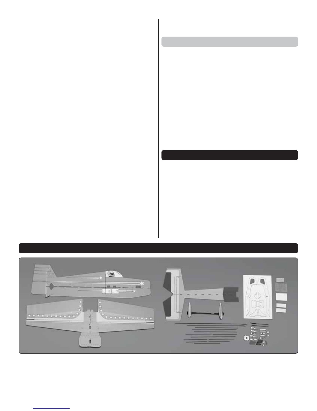
KIT INSPECTION
Before starting to build, take an inventory of this kit to make
sure it is complete, and inspect the parts to make sure they
are of acceptable quality. If any parts are missing or are not
of acceptable quality, or if you need assistance with assembly,
contact Product Support. When reporting defective or missing
parts, use the part names exactly as they are written in the
Kit Contents list.
Great Planes Product Support
3002 N Apollo Drive, Suite 1 Ph: (217) 398-8970, ext. 5
Champaign, IL 61822 Fax: (217) 398-7721
E-mail: airsupport@greatplanes.com
KIT CONTENTS
3
Page 4
ASSEMBLY
Assemble the Bottom Half
CA GLUING TIPS
Assembling lightweight, foam models with CA can
occasionally prove to be frustrating, so here are a few
suggestions to help you end up with a well-fi nished model
free of excess glue, fi ngerprints and smudges:
A. Most important, be certain to use foam-safe CA and
CA accelerators. Some accelerators attack foam more than
others. We have found that Great Planes Pro CA Activator
in Aerosol form (GPMP6034) may be used with 3mm “fl at
foam” without any problem.
B. Even foam-safe CA — used in excess — can generate
enough heat while curing to melt or deform foam, so use
CA and activator sparingly.
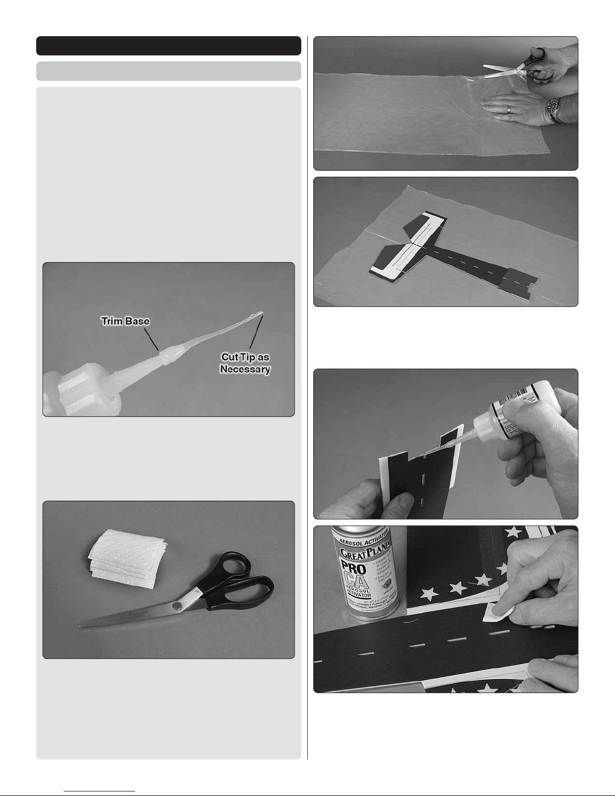
1. Split one of the larger plastic bags that came with the
❏
kit down one edge and unfold it over your workbench. Initial
assembly will be done over this sheet to keep from gluing
parts to your workbench.
C. CA Applicator Tips (HCAR3780) are highly recommended
and virtually required for use with thin CA. Trim the base
of the tip before pressing it onto the bottle to prevent the
tip from splitting. Simply cut off the end of the tip each
time it becomes clogged until it’s too short, then replace
it with another.
D. Small paper towel squares cut from two or three paper
towel sheets stacked on top of each other come in handy
for wiping residual CA off your model as you proceed.
E . Use care when wiping excess CA off the model—you
get only one or two chances before the CA will smear the
colored ink printed on the surface. Using CA sparingly will
minimize the necessity for wiping the airframe.
2. Glue the aft end of the fuselage to the wing/front end
❏
of the fuselage — it usually works best to apply medium CA
to one of the pieces, join them together right-side up over
the plastic sheet, hold tightly, wipe off excess CA and lightly
spray with accelerator.
4
Page 5
3. Flip the assembly over. Using care not to lay it back down
❏
over any uncured CA on the plastic sheet, wipe any excess
CA off the bottom.
5. Glue the bottom fuselage half to the wing/horizontal
❏
fuselage section. As you proceed, use a small builder’s square
to make certain the fuselage side is perpendicular.
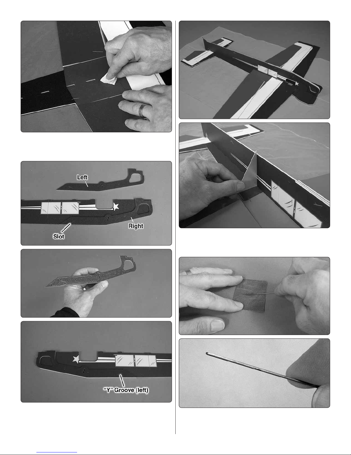
4. Glue the left and right side doublers to the bottom
❏
fuselage half — the left side is the one with the “Y” groove and
the right side has just a single slot — little glue is required, but
you do want to apply it evenly and get it all the way to the edges.
6. Use medium-grit sandpaper to round both ends of all
❏
the 1mm carbon fi ber braces — you don’t need to sand them
to a sharp point — just take off the rough edges.
5
Page 6

7. Lay weights over the structure to hold everything down,
❏
making sure the surfaces are fl at. Working from back-to-front,
test-fi t but do not glue all the 1mm carbon fi ber bottom
braces and the laser-cut plastic wing brace “posts” into
position. So as not to build any stress into the airframe which
could later cause a twist, it may be necessary to trim a mm
or two off one or two of the braces so they aren’t forced into
place and are the perfect length.
9. Glue the other end of the braces to the vertical part of
❏
the fuselage using a builder’s square as you proceed to make
sure the fuselage remains vertical.
8. Start by gluing the ends of the braces to the horizontal
❏
surfaces only — use just a drop of foam-safe CA so it doesn’t
wick down through the top. All the braces will be reinforced
with more glue later.
10. Test-fi t the landing gear and the ABS landing gear
❏
doublers into position. Align the wheels so they are parallel
with each other and study the assembly from all angles to
make sure everything is properly aligned. Once satisfi ed, glue
the gear and doublers into position.
6
Page 7

11. Glue the bottom motor mount doublers into position—
❏
work accurately here as the doublers help set the correct
motor right thrust.
12. Now that most of the structure has been braced and
❏
everything is pretty much “set,” temporarily lift the model off
the plastic sheet.
13. Place the structure back down onto the plastic sheet. Split
❏
one end of each of the the 1mm foam brace reinforcements
and glue them into position where shown — it’s easiest to
position the reinforcement, then add a drop or two of thin CA
followed by a quick shot of accelerator.
14. After all the reinforcements have been added you can
❏
remove the assembly from the plastic sheet and throw the
sheet away.
7
Page 8

Assemble the Top Half
1. Test fi t the top half of the fuselage to the assembly. If
❏
necessary, use a hobby knife to adjust some of the joining
tabs/notches to get a perfect fi t.
4. Fit, then glue the 1mm carbon fi ber top horizontal stab
❏
braces into position. Same as before, use a builder’s square to
be certain the vertical stab remains vertical and perpendicular
to the horizontal stab.
2. Carefully glue the top half of the fuselage into position —
❏
as you proceed, make sure the top remains parallel with the
bottom and perpendicular to the wing.
3. Glue the vertical fuselage post to the bottom the fuselage.
❏
5. Notch, position, then glue the round brace reinforcements
❏
into position.
6. Hinge the bottom of the rudder to the bottom fuselage
❏
half with the piece of hinge tape included with this kit.
8
Page 9

Hook Up the Ailerons
Refer to these photos for the next two steps.
7. Fit, then glue the motor mount into position — note that
❏
the motor mount should have slight up thrust and slightly more
right thrust (1 degree up, two degrees right to be precise).
Also note that the motor mounting holes are slightly rotated
counter-clockwise when viewed from the front.
8. Fit, then glue the foam motor mount doublers into
❏
position.
While working on the model for the next several steps it will be
handy to have a couple of small boxes or something similar,
to support the model upside-down.
1. Check the fi t of the pushrods in the four, laser-cut plastic
❏
control horns and in the extended aileron servo arm. If
necessary, enlarge the holes to fi t the pushrods — a #60
(.04") or 1mm drill is perfect, but a hobby knife may be used
instead. If using a hobby knife use care not to oversize the
holes as this will cause unwanted free play.
9
Page 10

2. If using the FlightPower ESC, solder the motor and
Cut
Cut
❏
battery connectors to the leads and use heat-shrink tubing
to protect the bullet connectors and solder joints. (As noted
in the front of the manual, the JST connector will have to be
replaced with a Deans micro.)
4. Use a hobby knife to enlarge the holes in the servo arm
❏
for the screws in the extended aileron servo arm, then join
the two with 1.5mm x 3mm Phillips screws and a drop of CA.
3. Temporarily connect your aileron servo, ESC and battery
❏
to your receiver and power the system up with your transmitter.
Also make sure the trims and sub-trims are centered in your
transmitter programming. Find the orientation on the aileron
servo arm that will be neutral as shown in the illustration, then
cut off the unused arms.
5. Install the aileron servo and mount the servo arm with
❏
the aileron pushrods. Glue the servo into position with foamsafe CA or canopy glue.
10
Page 11

6. If you wish to install the optional aileron servo cover, glue
❏
it into position now. The cover assists slightly in holding the
aileron servo into position and fi lls most of the empty space
around the servo simply for appearances, but if your aileron
servo is securely glued into position the cover is not necessary.
7. Use a piece of medium-grit sandpaper to roughen all
❏
four of the wire Z-bend pushrod ends.
8. Install a Z-bend pushrod wire end into two of the control
❏
horns. Fit, but do not glue the horns into the slots in the
ailerons, then slip pieces of the included shrink tubing over
the pushrod ends and the aileron pushrods.
10. Place the “clamp” you made in the previous step over
❏
the end of one of the ailerons and the fuselage to hold the
aileron centered. With the aileron servo connected to your
receiver and transmitter still on, add a drop or two of thin
CA to the pushrod wire and the pushrod, slide the shrink
tubing into position, then use a medium-duty soldering iron
or an adjustable soldering iron on medium heat to shrink
the tubing —be diligent to work the tip of the iron all the way
around the tubing, touching it from all angles. Of course, keep
the soldering iron away from the foam.
9. Make a small “clamp” from the piece of leftover foam from
❏
the aileron servo cutout that was in the top half of the fuselage.
11. Connect the other aileron pushrod to the other aileron
❏
horn the same way.
11
Page 12

12. With the radio still on, turn the airplane upright. If
Elevator Rudder
3/8"
[10mm]
1/2"
[13mm]
❏
necessary, slide the aileron horns forward or back in the slots
in the ailerons to get the ailerons perfectly centered with the
fuselage. Once everything aligns glue the aileron horns to
the ailerons with CA.
Hook Up the Elevator and Rudder
1. Center the elevator and rudder servo arms with the radio
❏
on and cut off the unused arms.
2. Install, but do not glue the servos into position.
❏
3. Fit the laser-cut plastic pushrod guides through the
❏
fuselage — the shorter guide is the front.
4. Take the servo arms off the servos and connect the
❏
pushrods to the servo arms — holes 1/2" [13 mm] out for the
rudder and 3/8" [10mm] out for the elevator should get you
the correct 3D throws with the servo end points set at 100%
in your transmitter.
5. Guide the pushrods down through the guides and reinstall
❏
the arms onto the servos.
6. Fit the Z-bend pushrod ends into the elevator and rudder
❏
control horns and fi t the horns into the slots in the elevator
and rudder, but do not glue them in yet.
7. With the radio system on and the servos and rudder and
❏
elevator centered, glue the pushrod ends to the pushrods with
CA and the shrink tubing.
8. Align the guides so the pushrods have the straightest,
❏
smoothest path between the servos to the control horns. Glue
the servos, guides and control horns into place.
Refer to these photos while hooking up the elevator and
rudder.
12
Page 13

Final Assembly
1. Now that the structure is completely assembled, go
❏
back and reinforce any glue joints where necessary — don’t
build up large fi llets of glue — just a drop of thin, foam-safe
CA here-and-there where necessary.
2. Mount the motor with the three included Phillips screws.
❏
Balance the propeller, then mount the propeller to the motor.
5. Stick the rougher, “hook” side of the included adhesive-
❏
back Velcro to the battery mounting location. If, for some reason,
you would rather mount your battery in another location you
can use the included foam cover to fi ll the existing hole, then
cut a new battery mounting location where preferred. Keep in
mind that the Laser balances within the balance range with both
2S and 3S batteries mounted in the existing location provided.
3. Take a few minutes to think about the mounting location
❏
of the receiver, ESC and battery and where you will route
and secure the wiring. A 5/16" [8 mm] hole will need to be
cut wherever necessary for passing the power wires from the
battery. (A brass tube sharpened on the end works well for
cutting a perfect hole.)
4. When ready, connect the servos and ESC to the receiver
❏
and connect the ESC to the motor, then use the included
double-sided foam mounting tape (not included) to mount the
receiver and ESC. Use a hobby knife to cut slits through the
foam for one or both of the laser-cut plastic U-shaped cable
clamps for neatly holding down the servo wires. Install, then
use foam-safe CA to glue the clamp into position.
6. Apply a small patch of the included softer, “loop” side of
❏
the included Velcro to your batteries — it doesn’t take much to
hold the battery in place. Using too much makes the battery
diffi cult to remove.
13
Page 14

GET THE MODEL READY TO FLY
3/8" [10mm]
ahead of spar
1/4" [6 mm]
behind spar
FULL
THROTTLE
RUDDER
MOVES
RIGHT
ELEVATOR
MOVES DOWN
RIGHT AILERON
MOVES UP
LEFT AILERON
MOVES DOWN
4-CHANNEL RADIO SET UP (STANDARD MODE 2)
Check the C.G.
With any of the 2S or 3S batteries recommended the Laser
should balance within the recommended C.G. range, but
since the C.G. has such a great effect on how the model fl ies
it’s a good idea to check it. Plus, knowing where the model
balances will give you a good idea how it will fl y.
add stick-on lead ballast to the nose or tail to get it to balance
within the range. The farther back the Laser balances the
more it will “fl oat” and the more responsive it will be, but if it’s
too responsive it could be too diffi cult for inexperienced pilots
to control. The farther forward the Laser balances the more
stable, but the less responsive it will be. Balancing the Laser
within the recommended range should provide the correct
ratio of stability, maneuverability and response for most pilots.
Check the Control Directions
With the Laser ready-to-fly and all of the components
mounted and installed including the battery, lift it upside-down
positioning it on your fi ngertips until you can get it to sit level.
The recommended, starting balance point is directly over
the main spar, but as long the Laser balances 3/8" [10mm]
ahead of the spar or 1/4" [6mm] behind the spar it will be
balanced within the recommended range. If the Laser balances
outside of this range it is advisable to relocate the battery or
Be certain the controls respond in the correct direction
according to the transmitter inputs. If necessary, use the
servo reversing function in your transmitter to get the controls
to respond in the correct direction.
Set the Control Throws
The throws are measured at the widest point (front-to-back)
of each surface with the bottom of the fuselage propped up
so the wing and horizontal stabilizer are level.
14
Page 15

These are the recommended control surface throws:
Ground Check
ELEVATOR
RUDDER
AILERONS
NORMAL RATE
Up
1"
[25mm]
17°
Right
1- 3/4"
[44 mm]
27°
Up
1-1/2"
[38 mm]
24°
Down
1"
[25mm]
17°
Left
1- 3/4"
[44 mm]
27°
Down
1-1/2"
[38 mm]
24°
3D RATE
Up
2"
[ 51mm]
35°
Right
3"
[ 76 mm]
51°
Up
2-1/2"
[64mm]
42°
Down
2"
[51mm]
35°
Left
3"
[ 76 mm]
51°
Down
2-1/2"
[64mm]
42°
Identify Your Model
If fl ying your Laser outdoors, use a fi ne-point felt-tip pen to
write your name, address and telephone number on the plane.
This is required for fl ying outdoors at AMA-sanctioned events.
Don’t forget to perform an operational ground range check
of your radio control system according to the manufacturer’s
instructions. Also be certain to set the failsafe function in your
transmitter so in case of loss of signal (or if you inadvertently
turn off the transmitter before disconnecting the battery) the
motor will not run
Flying
The Laser 200 doesn’t exhibit any unusual tendencies that you
need to be made aware of ahead of time. On normal rates it’s
a gentle fl yer that can be maneuvered around the gym slowly.
In the hands of experienced pilots on 3D rates it’s ready to take
whatever you can dish out. Just take it easy with your Laser
for the fi rst fl ight, trimming the controls for straight-and-level
fl ight and getting used to the way it responds. Take mental
notes of any C.G., control throw or mixing changes required
to suit your taste.
15
Page 16

 Loading...