

Page 1
® ®
The Profile Alternative
.40-SIZE RADIO CONTROLLED MODEL AIRPLANE KIT
INSTRUCTION MANUAL
Wing Span: 44 in.
Wing Area: 627 sq. in. Weight: 3.5 lb.
Length: 34.5 in. Wing Loading: 13 oz./sq. ft.
Engine: .35 to .51 Radio: 4 ch./5 servos
2
READ THROUGH THIS INSTRUCTION MANUAL FIRST. IT
CONTAINS IMPORTANT INSTRUCTIONS AND WARNINGS
CONCERNING THE BUILDING AND USE OF THIS MODEL.
WARRANTY
Tower Hobbies®guarantees this kit to be free from defects in
both material and workmanship at the date of purchase. This
warranty does not cover any component parts damaged by use
or modification. In no case shall Tower Hobbies’ liability exceed
the original cost of the purchased kit. Further, Tower Hobbies
reserves the right to change or modify this warranty without
notice.
In that Tower Hobbies has no control over the final assembly or
material used for final assembly, no liability shall be assumed nor
accepted for any damage resulting from the use by the user of
the final user-assembled product. By the act of using the
user-assembled product, the user accepts all resulting liability.
If the buyers are not prepared to accept the liability associated
with the use of this product, they are advised to return this kit
immediately in new and unused condition to Tower Hobbies.
The Fun 51 is not a toy, but rather a sophisticated, working
model that functions very much like an actual airplane.
Because of its performance, the Fun 51, if not assembled and
operated correctly, could possibly cause injury to yourself or
spectators and damage property.
To make your R/C modeling experience totally enjoyable, we
recommend that you get experienced, knowledgeable help with
assembly and during your first flights. You’ll learn faster and
avoid risking your model before you’re truly ready to solo.
You can contact the national Academy of Model Aeronautics
(AMA), which has more than 2,500 chartered clubs across the
country. Through any one of them, instructor training programs
and insured newcomer training are available.
Contact the AMA at the address or toll-free phone number
below.
Academy of Model Aeronautics
5151 East Memorial Drive
Muncie, IN 47302-9252
Tele. (800) 435-9262
Fax (765) 741-0057
Web Site: HTTP://WWW.MODELAIRCRAFT.ORG
© Copyright 1999 Version 1.1
PRINTED IN USA FP51PO2
Page 2
3
Congratulations!
If you have been looking for a way to put the
FUN
back into
your Sunday flying, you have just found it. The FUN 51 is a
nimble little
profile hot-dogger
that assembles in only a few
hours and is easy on the budget. It does not require any special
building or flying skill - just a few hand tools and a little taildragger time. With its oversized control surfaces it turns, loops
and rolls in the blink of an eye. But the thick, high lift airfoil and
light wing loading allow the plane to slow
way
down for gentle
spot landings. If equipped with an engine like the Tower .40 it’s
possible to be airborne in a matter of feet, zip through three
rolls, loop on its own axis, and then go into the “hover” mode
while waiting for your buddies to get off the ground. What more
can we say? The Fun 51 maximizes fun for minimal cost and time!
ITEMS REQUIRED FOR COMPLETION
We strongly recommend using
Great Planes
®
and
Tower
accessories for all your modeling needs.
❍ 4 Channel radio with 5 servos and a Y-harness
(TOWJ40**) (TOWM4520 x 5)
❍ .35 - .51 2/S or .40 - .52 4/S engine (Tower .40 ABC ideal)
❍ 4 - 6 oz. Fuel tank (GPMQ4101) or (GPMQ4102)
❍ (2) 2-1/2" Wheels (GPMQ4223)
❍ 1" T ail wheel (GPMQ4241)
❍ (2) 3/32" Wheel collars (GPMQ4302)
❍ 12" Medium fuel tubing (GPMQ4131)
❍ (2) Rolls covering film (Top Flite
®
MonoKote®or
T ower T o werKote®)
❍ 1/4" Foam rubber (HCAQ1000)
❍ 2-1/4" Spinner (GPMQ4517 Red)
SUPPLIES
❍ 1 oz. Thin CA (GPMR6002)
❍ 1 oz. Medium CA (GPMR6008)
❍ 6-minute epoxy (TOWR3300)
❍ 30-minute epoxy (TOWR3350)
❍ Balsa filler (HCAR3401)
❍ Masking tape (GPMR1010)
❍Wax paper
❍ Isopropyl rubbing alcohol (70%)
❍ Microballoons (TOPR1090)
TOOLS
❍ Sanding block and sand paper (coarse, medium, fine)
❍ Hobby knife and #11 blades (TOWR1010) (TOWR1015)
❍ Single edge razor blades (TOWR1005)
❍ Razor saw
❍ Razor plane
❍ Electric drill
❍ Drill bits - 1/16",1/8", 5/32"
❍ Small Phillips and flat blade screwdrivers
❍ Pliers with wire cutter
❍ Sealing iron and heat gun (TOWR3250) (TOWR3200)
❍T-Pins (HCAR5150)
❍ Straightedge with scale
4
ITEMS REQUIRED FOR COMPLETION ....................................................................4
SUPPLIES..................................................................................................................4
TOOLS......................................................................................................................4
DIE PATTERNS..........................................................................................................5
IMPORTANT BUILDING NOTES..............................................................................6
BUILD THE FUSELAGE, FIN & RUDDER ..................................................................7
BUILD THE HORIZONTAL STABILIZER & ELEVATORS..........................................11
BUILD THE WING & AILERONS.............................................................................12
FINAL ASSEMBL Y....................................................................................................19
BALANCE THE AIRPLANE LATERALL Y....................................................................20
COVERING & FINISHING......................................................................................20
Repairing surface dings .....................................................................................21
Final sanding .....................................................................................................21
Cover the structure with TowerKote™................................................................21
Recommended covering sequence ....................................................................21
FINAL HOOKUPS AND CHECKS............................................................................22
BALANCE YOUR MODEL .......................................................................................24
CONTROL SURFACE THROWS ..............................................................................25
PREFLIGHT.............................................................................................................26
Balance the prop...............................................................................................26
Charge the batteries..........................................................................................26
Ground check the model...................................................................................26
Range check your radio.....................................................................................26
SAFETY PRECAUTIONS..........................................................................................27
FLIGHT...................................................................................................................27
Takeoff...............................................................................................................28
Flying.................................................................................................................28
Landing .............................................................................................................28
TABLE OF CONTENTS
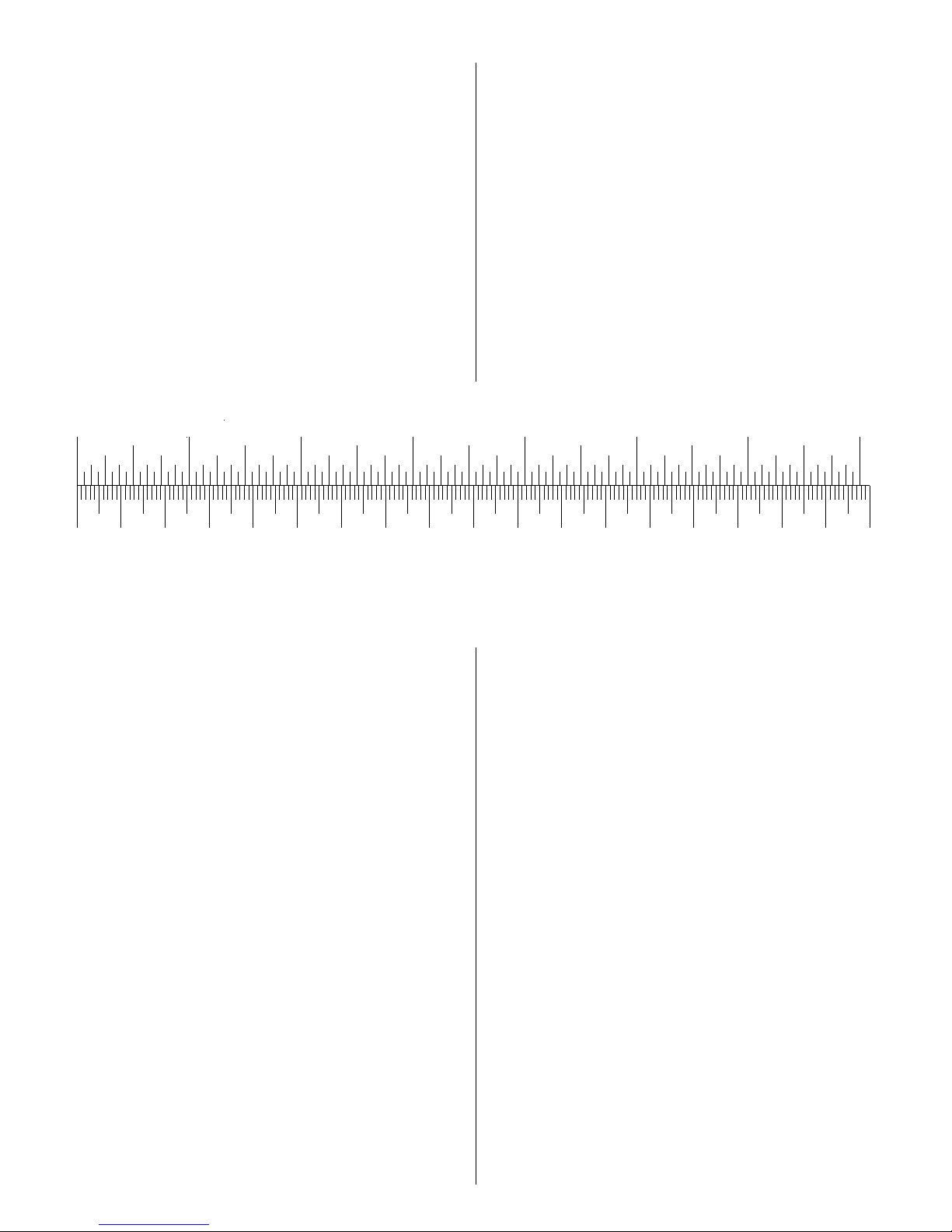
Inch Scale
0" 1" 2" 3" 4" 5" 6" 7"
0 10 20 30 40 50 60 70 80 90 100 110 120 130 140 150 160 170 180
Metric Scale
Page 3
5
6
Remember: Take your time and follow directions to end up with
a well-built model that is straight and true.
Please inspect all parts carefully before starting to build! If any
parts are missing, broken or defective, please call us at
(800) 637-6050 (Outside the USA - (217) 398-3636) and we’ll
be glad to help. Or, you may send an e-mail to:
productsupport@towerhobbies.com
IMPORTANT BUILDING NOTES
Unroll the plan sheets, then reroll the plans inside-out to make
them lie flat.
Sort through the sticks and sheets, grouping them by size.
Masking tape can be used to bundle matching sheets and sticks.
Using a felt tip or ball point pen, lightly write the part name or
size on each piece or bundle. Refer to the parts list and plans for
sizes and quantities. Use the die-cut patterns shown on page 5
to identify the die-cut parts and mark them before removing
them from the sheet. Save all scraps. If any of the die-cut parts
are difficult to remove, do not force them! Instead, cut around
the parts with a hobby knife or lightly sand the back of the sheet.
After removing the die-cut parts, use your sanding block to
lightly sand the edges to remove any die-cutting irregularities.
Work on a flat surface. Cover the plans with wax paper or Great
Planes Plan Protectors (GPMR6167). There are notes on the
plans that tell you what material to use to make each part.
When instructed to
test fit
parts, this means DO NOT USE GLUE
until you are satisfied that everything fits properly – THEN glue
the parts together when instructed to do so.
The easiest way to cut balsa sticks is with a single edge razor blade
or razor saw. Position the stick over the plan, mark its size and then
cut the part on a piece of scrap lumber. A modeling miter box
works well for cutting square corners and 45 degree gussets.
We, as the kit manufacturer, provide you with a top quality kit
and great instructions, but ultimately the quality and flyability
of your finished model depends on how you build it;
therefore, we cannot in any way guarantee the performance of
your completed model, and no representations are expressed
or implied as to the performance or safety of your completed
model.
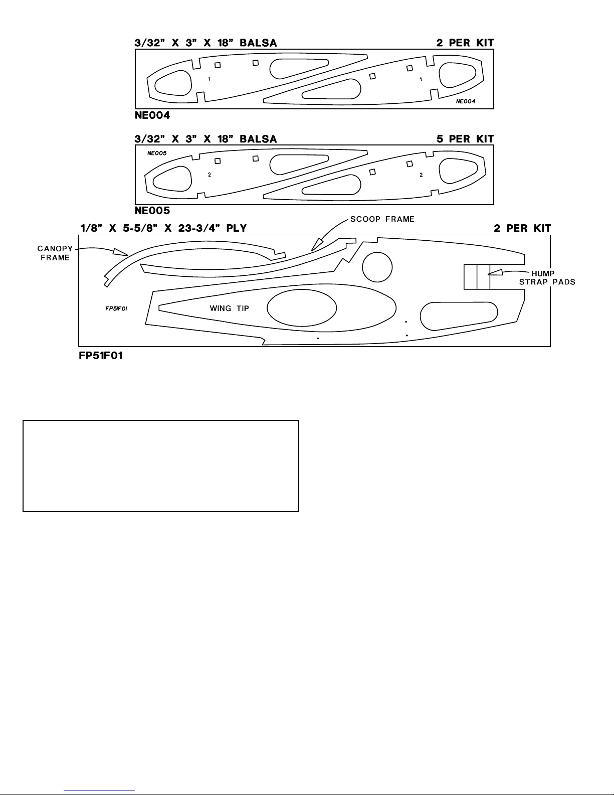
DIE PATTERNS
Page 4
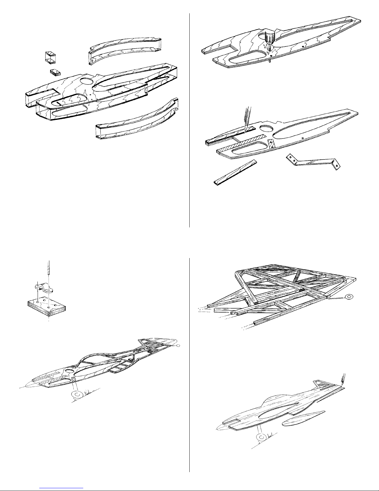
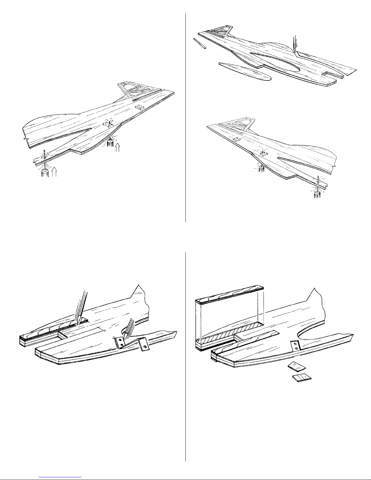
BUILD THE FUSELAGE, FIN AND RUDDER
❍ (1) Punch out the plywood die-cut parts. Use 30-minute
epoxy to laminate the fuselage core, scoop frame, canopy frame
& hump strap pads together.
Note: The airfoil shape that you punched out of the fuselage
core will be used for the wing tips in step 14, of “Build The
Wing And Ailerons.” The front of the engine cut-out, as well as
the ellipse from the wing tips, is not needed during construction.
You may save these for later use as scrap.
❍ (2) Drill a 5/32" diameter hole through the laminated fuselage
core at the two landing gear center marks and also at the
balance point.
❍ (3) Using the 1/8" x 1/2" x 6" plywood engine doublers and
the aluminum landing gear struts, mark the area on the fuselage
core as shown. When installing the side sheeting, do NOT apply
glue to the areas you just marked. Be sure to mark both sides of
the assembly.
7
❍ (4) Using a hump strap as a
template, drill four 1/16" diameter
holes through the two hump strap
pads. Set these pads aside for now.
Note: Use only one of the six 1/4" x 3/8" x 36" balsa sticks to
build the fin and rudder.
❍ (5) Pin the entire fuselage portion of the plan over your
building board and cover the plan with wax paper. Build the
fuselage and fin over the plan as shown. Glue the hump strap
pads to scrap balsa shims as shown. Without glue, use 1/4"
leftover balsa spacers to maintain stab slot width.
❍ (6) Build the rudder over the plan as shown.
❍ (7) Glue two 3/32" x 3" x 36" balsa sheets to one side of the
fuselage frame. Make sure that you do NOT glue the sheeting to
the areas that you marked in step 3. Trim the sheeting around
8
Page 5
the perimeter and the wing cutout. Use leftover balsa trimmed
from the aft end of the fuse to fill in the top of the canopy and
scoop area.
❍ (8) Take the fuselage off the building board. Drill 1/16"
diameter holes through the balsa sheeting using the four pilot
holes in each hump strap pad and the balance hole as guides.
Drill 5/32" holes through the balsa skin for the landing gear. These
will help you position the landing gear later. Refer to the plan for
the length of the stab slot and then measure and cut the opening.
❍ (9) Flip the fuselage over and sheet the open side using (2)
3/32" x 3" x 36" balsa sheets. Do not glue the marked areas from
step 3. Trim the perimeter and wing opening as you did in step 7.
❍ (10) Drill 1/16" diameter holes through the balsa sheeting using
only the rear two pilot holes in each hump strap pad and the
balance hole. Drill through the landing gear holes with a 5/32" bit.
9
❍ (11) Using the engine mount doublers and a landing gear strut
as templates, mark the balsa to be trimmed from the unglued area
of the fuselage core. Mark both sides of the fuselage.
❍ (12) Trim the balsa from the unglued areas on both sides of
the fuselage. Use 30-minute epoxy to glue the plywood engine
doublers onto the plywood skeleton on both sides.
This completes the basic construction of the fuselage. Round the
perimeter and flat sand the sides. Put the fuselage aside for now
and move on to the horizontal stabilizer.
10
Page 6

BUILD THE HORIZONTAL STABILIZER
AND ELEVATORS
❍ (13) Pin the horizontal stabilizer and the elevators portion of
the plan to the building board. Cover this portion with wax
paper. Trim the 1/4" x 3" x 4-3/8" balsa stabilizer platform as
shown. Use the plan for the correct outline.
❍ (14) Assemble the stabilizer over the plan using the materials
specified on the plans.
❍ (15) Assemble the elevators over the plan as shown.
❍ (16) Locate the elevator joiner wire and drill a 1/8" or 9/64"
diameter hole in each elevator at the location shown on
the plan.
11
❍ (17) Carve out the joiner wire clearance on each elevator as
shown. Test fit the wire joiner until the fit is as shown.
This completes the stab and elevators. Put them aside for now
and let’s move on to the wing construction.
BUILD THE WING AND AILERONS
Note: The wing is built over the plan, with the bottom of the
wing facing up.
Refer to the following illustration when performing the next 3
steps.
Pin the wing portion of the plan to the building board.
Cover the plan with wax paper.
❍(1) Use the 1/8" x 3/8" x 24" balsa sticks to make the 44" trailing
edge by joining them with a diagonal splice at the centerline.
❍ (2) Pin two 1/4" x 1-1/8" x 24" balsa leading edge sticks over
the wing plan to create a temporary trailing edge fixture. These
fixture sticks are used later to make the wing
leading edge
. Cover
the fixture with wax paper. Then pin the 1/8" x 3/8" x 44" trailing
edge to the top edge.
❍ (3) Make two 44" wing spars by cutting and joining 1/4" x 3/8"
x 36" balsa sticks using a diagonal splice at one end. Cut the
1/4" x 3/8" x 30" balsa spar doubler in half to make two 15" sticks.
Bevel both ends of spar doublers and glue them to the spars
where shown on the plan. Pin the bottom spar assembly into
position over the plan.
12
Page 7

Important: When positioning the spars, be sure that the top and
bottom splices are at opposite ends of the wing.
❍ (4) Glue the four #1ribs onto the bottom spar and trailing
edge over the locations shown on the plan. Make sure that the
1/4" square holes for the servo mounting rails are up as shown
and that the ribs are centered on the trailing edge.
Glue the 1/8" x 7/8" x 8-1/4" ply leading edge doubler onto the
front of the #1ribs.
Cut the 1/4" x 15" hardwood servo mounting rails to 8-1/4". Save
the leftover pieces for aileron servo mounting. Slide a servo
mounting rail through the front and back square holes as shown
and glue them securely into position.
❍ (5) Glue all of the #2 ribs onto the bottom spar and trailing
edge. Once again make sure all of the 1/4" square holes are at
the top. Cut and glue four 1/4" square hardwood aileron servo
mounting rails into the square holes in the proper ribs.
Splice two 3/32" x 7/8" x 24" balsa sheets together with
a diagonal cut to make the sub-leading edge. Glue the
sub-leading edge to the front of all #2 ribs and to the leading
edge doubler.
13
❍ (6) Glue the top spar assembly into the notches in all of the
wing ribs.
Cut and glue the 1/16" x 3" balsa shear webs securely to the
front of the spars.
Diagonally splice the two 3/32" x 7/8" x 24" balsa trailing edge
sheets at the centerline. Glue the trailing edge sheeting to the
ribs and to the 1/8" x 3/8" balsa trailing edge.
❍ (7) Bevel the sub-leading edge with a long sanding block so
that it is flush with the tops of all wing ribs as shown.
Refer to the plan and sketch above, then use three 3/32" x 3" x 36"
balsa sheets, spliced diagonally, to make two 44" long leading
edge sheets.
Set one 44" sheet aside for the time being.
Glue a leading edge sheet to the ribs, beveled sub-leading edge
and upper spar. Position the splice as shown on the plan.
Note: The sheeting will only cover the front half of the spar.
14
Page 8

❍ (8) Temporarily position a servo and cut 3/32" balsa sheeting
to fit the two aileron servo areas and the center section. Leftover
sheeting can be used along with a 3/32" x 3" x 36" sheet supplied
for this purpose. Use the plan to determine the hatch location.
❍ (9) Cut, fit and glue the 1/4" square, hard balsa hatch mount
rails between the ribs as shown on the plan. Trim the 1/16" x 31/4" x 5-1/4" plywood hatch cover to fit as shown. See the plan
for the correct location of the six #2 x 3/8" flat head hatch
screws. Drill and countersink the six screw holes.
Drill 1/16" pilot holes into the hatch mount rails. Test fit the
hatch to the wing using all six screws. Remove the hatch when
you are satisfied with the fit. Apply a couple of drops of thin CA
to each screw hole in the mounting rails to harden the balsa.
15
❍ (10) Trim and glue the 3/32" x 1/4" balsa cap strips to the
wing ribs.
❍ (11) Remove the wing from the building board and turn it over.
The trailing edge fixture is no longer needed to support the TE of
the wing. Sand the sub-leading edge so that it’s flush with the tops
of all ribs as shown. Glue the second 3/32" x 3" x 44" leading
edge sheet to the ribs, beveled sub-leading edge and spar.
16
Page 9

❍ (12) Cut, fit and glue the 3/32" x 3" balsa wing center
sheeting and 3/32" x 1/4" balsa cap strips to the wing ribs.
❍ (13) Sand the top and bottom leading edge sheeting until it is
flush with the front face of the sub-leading edge, as shown.
Diagonally splice, at the wing centerline, the two 1/4" x 1-1/8"
x 24" balsa leading edge pieces.
You used these pieces as a
trailing edge fixture earlier in the wing construction.
Glue them
to the the sub-leading edge
Carve and sand the leading edge to shape as shown.
17
❍ (14) Sand both ends of the wing smooth. Glue the die-cut
plywood wing tips onto the sanded wing ends.
Sand the edge of the airfoil to insure the wing tip is flush with
the wing.
❍ (15) With the wax paper still positioned over the plan, build
both ailerons using the sticks specified on the plan.
❍ (16) Draw a centerline on the trailing edge of the fin, stabilizer
and wing. Refer to the plans, then mark and cut the hinge slots.
18
Page 10

❍ (17) Mark and cut matching hinge slots on all control surfaces.
A #11 blade in a hobby knife works well for cutting the slots.
Test fit (do not glue) the control surfaces to the stab, fin and wing.
❍ (18) When you are satisfied with the fit, remove the hinges
and bevel the leading edge of the ailerons, elevators and rudder.
Round the remaining perimeter edges of the rudder, fin, stab,
ailerons and elevators.
FINAL ASSEMBLY
❍ (1) Draw a centerline from the leading edge to trailing edge
on the top of the wing and stab. Draw a parallel line 1/4" on
each side of the center lines for reference, so you will know
when the wing and stab are centered in the fuse. Slide the wing
and horizontal stab into the fuselage. Make sure the fuselage is
centered between the reference lines.
19
❍ (2) Carefully check the alignment of the wing and stab to the
fuselage as shown. Permanently glue the wing and stab to the
fuselage with 30-minute epoxy.
After the epoxy has cured, fill any gaps with a mixture of micro
balloons and epoxy.
Cut the slot for the tail gear bracket in the aft end of the fuse and
check its fit. Hold the rudder in position and mark the location
of the tail gear steering arm. Drill a 1/8" diameter hole into the
rudder at the marked location. Notch the rudder to accept the
protruding tail gear bracket and wire.
COVERING AND FINISHING
We recommend using a light-weight film covering material such
as TowerKote™to finish your Fun 51 (Top Flite MonoKote®was
used to cover the model shown on the cover of this instruction
manual). Apply the film following the manufacturer’s
instructions using the sequence we suggest for best results.
Balance the airplane laterally
Note: Do not confuse this procedure with “checking the
C.G.” or “balancing the airplane fore and aft.” That very
important step will be covered later in the manual.
1. Temporarily install the engine (with muffler), landing gear,
radio equipment, fuel tank (3/4 full) and battery.
2. With the wing level, lift the model by the engine propeller
shaft and the fin (this may require two people). Do this several
times.
3. If one wing always drops when you lift the model, it means
that side is heavy. Balance the airplane by gluing a weight to
the inside of the other wing tip.
Note: An airplane that has been laterally balanced will track
better in loops and other maneuvers.
20
Page 11

REPAIRING SURFACE DINGS
Many surface blemishes on a framed model are caused by
bumps and balsa chips on the work surface. This type of ding is
best repaired by applying a drop or two of window cleaner or
tap water to the blemish, then running a hot sealing iron over
the spot to expand the wood fibers. After the surface has dried,
sand the
expanded
area smooth.
FINAL SANDING
Fill any large scuffs or dings. Then sand the entire structure with
progressively finer grades of sandpaper, ending with 320-grit.
COVER THE STRUCTURE WITH TOWERK OTE
The Fun 51 does not require any painting to obtain the scheme
shown on the box, as all of the finish is MonoKote.
Make sure the structure is smoothly sanded with 320-grit
sandpaper. Remove all dust from the structure with a vacuum
cleaner and Top Flite
®
Tack Cloth so the covering will stick well.
Cover the aircraft using the sequence that follows. Make sure the
covering is thoroughly stuck to the structure and all edges are
sealed. Use a Top Flite Hot Sock™on your covering iron to avoid
scratching the finish.
When covering areas that involve sharp junctions, like the tail
section or around the root end of the wing, cut narrow strips
(1/4" to 3/8") and apply them in the corners before covering the
major surfaces. The larger pieces of covering will overlap and
capture these smaller pieces. This technique also bypasses the
need to cut the covering in these areas after it has been applied.
DO NOT, under any circumstances, attempt to cut the covering
material after it has been applied to the fin and stab, except
around the leading and trailing edges.
RECOMMENDED COVERING SEQUENCE
❍ 1. Tail junction strips as described above
❍ 2. Wing/fuse junction
❍ 3. TE surfaces of wing
❍ 4. Bottom of left and right wing panels
❍ 5. Top of left and right wing panel and wing tips
❍ 6. Fuse sides (overlap at top and bottom)
❍ 7. Stab bottom
❍ 8. Stab top
❍ 9. Fin left and right side
❍ 10. Rudder left and right side
❍ 11. Bottom of elevators
❍ 12. Top of elevators
❍ 13. Ends of ailerons
❍ 14. Bottom of ailerons
❍ 15. Top of ailerons
❍ 16. Hatch cover
21
FINAL HOOKUPS AND CHECKS
❍ (1) Lay the control surfaces over the plans for reference and
mark the location of the hinge slots.
Cut through the covering at each hinge slot on the control
surface and its mating part.
Roughen the elevator joiner wire with coarse sandpaper. Pack
30-minute epoxy into the holes in the elevator halves with a
toothpick. Insert the joiner wire into both elevators and place
the assembly on a flat surface to cure. Be sure the elevator
leading edge is straight before the epoxy cures.
❍ (2) Install the elevator and ailerons using hinges. When
satisfied with the fit, place a few drops of CA glue into both
sides of each hinge. After the CA has cured, move each control
surface to loosen them up.
Put a dab of petroleum jelly on the top and bottom of the tail
gear bracket where the wire passed through it. Pack the hole in
the rudder with 30-minute epoxy, Then, fit the rudder in position
with hinges. Apply thin CA to both sides of each hinge.
❍ (3) Poke two holes through the covering at the bolt locations
for the landing gear struts. Bolt the struts to the fuselage, using
two 6-32 x 3/4" pan head screws and two 6-32 lock nuts.
Install the wheels on the landing gear struts using two 8-32
x 1-1/4" bolts, two #8 flat washers and four hex nuts.
22
Page 12

❍ (4) Assemble your 4 or 6 oz. fuel tank.
Open the three “closed loop” screw eyes to make hooks as
shown. Locate the position of the hooks and screw them into the
fuselage. Place a piece of 1/4" foam between the fuselage side and
the tank and rubber band the tank in place as shown. You may
want to use three rubber bands to secure the tank to the aircraft.
❍ (5) Install a spinner on your engine. Position the engine so the
back edge of the spinner is approximately 3/32" in front of the
fuselage. Mark the location of the engine mounting holes.
❍ (6) Drill four 1/8" holes through the ply engine mounts. Use
two #6 washers between the engine and the mounts under the
two front holes. This will provide the required 2 degrees of right
thrust. Secure the engine with four 4-40 x 1" pan head bolts,
lock nuts and washers.
❍ (7) Install all five control horns. Drill the required 3/32" holes,
using a control horn as a locating template. Secure the horns with
two 2-56 x 5/8" machine screws. Trim off the excess threaded
portion of the screws after tightening.
23
❍ (8) Install the radio receiver, battery, switch and servos. Cut
the 35" pushrods to fit for the rudder and elevator. Make the
aileron pushrods from the excess length trimmed from the
elevator and rudder pushrods. Install the nylon hump straps with
#2 x 3/8" screws. Slide a silicone retainer onto each nylon
clevis. Screw a clevis onto each pushrod about 14 turns. Slide
the pushrods into position, clip the clevises onto the horns and
slide the silicone retainer over the clevis to lock in place.
❍ ( 9) Center the servo horns by turning on the radio and
centering the trim switches. Mark the position on the pushrod
where the pushrod intersects the servo horn. Make a 90 degree
bend on the mark. Cut off the excess wire about 3/8" above the
bend. Enlarge the hole in the servo horn to 5/64".
❍ (10) Insert the pushrod end and
secure it in position with a nylon
Faslink. Bend the throttle pushrod to fit
your engine throttle arm.
Thread the antenna wire out along the fuselage and let it trail off
behind the rudder.
BALANCE YOUR MODEL
Note: This section is VERY important and must NOT be
omitted! A model that is not properly balanced will be unstable
and possibly unflyable.
❍ (1) Hang the model by a string threaded through the balance
hole on the bottom of the model. This is the balance point at
24
FasLink
2-56 (.074")
Pushrod Wire
1/16"
Servo Horn
Page 13

which your model should balance for your first flights. Later, you
may wish to experiment by shifting the balance up to 1/4"
forward or back to change the flying characteristics. Moving the
balance forward may improve the smoothness and arrow-like
tracking, but it may then require more speed for takeoff and
make it more difficult to slow down for landing. Moving the
balance aft makes the model more agile with a lighter and
snappier feel. In any case, please start at the location we
recommend and do not at any time balance your model outside
the recommended range.
❍ (2) With all equipment installed (ready to fly) and an empty
fuel tank, lift the model at the balance point. If the tail drops
when you lift, the model is “tail heavy” and you must move
weight toward the nose to balance. If the nose drops, it’s “nose
heavy” and you must move weight toward the tail to balance.
Try to balance the model by changing the position of the
receiver battery and receiver. If this is not enough, you may
need to add stick-on weights to the tail or a Great Planes spinner
weight (GPMQ4645) to the nose.
CONTROL SURFACE THROWS
Control throw adjustment
❍ (1) By moving the position of the clevis at the control horn
toward the outermost hole, you will decrease the amount of
throw of that control surface. Moving it toward the control
surface will increase the amount of throw. If these adjustments
don’t accomplish the job, you may need to work with a
combination of adjustments by also repositioning the pushrod at
the servo end. Moving the pushrod toward the splined shaft on
the servo will decrease the control surface throw — outward
will increase it.
We recommend the following control surface throws as a
starting point:
High Rate Low Rate
ELEVATOR: 7/8" up [22mm] 1/2" up [13mm]
7/8" down [22mm] 1/2" down [13mm]
RUDDER: 1-3/4" right [44.5mm] Same as high rates
1-3/4" left [44.5mm]
AILERONS: 1" up [25.4mm] 5/8" up [16mm]
1" down [25.4mm] 5/8" down [16mm]
25
Note: Throws are measured at the widest part of the elevators,
rudder and ailerons. If your radio does not have dual rates, set the
control throws halfway between the specified high and lo w r ates.
❍ (2). Make sure the control surfaces move in the proper
direction as illustrated in the following sketch.
PREFLIGHT
Balance the prop
Balance your propellers carefully before flying. An unbalanced
prop is the single most significant cause of damaging vibration.
Not only will engine mounting screws and bolts vibrate out,
possibly with disastrous effect, but vibration will also damage
your radio receiver and battery.
Charge the batteries
Follow the battery charging procedures in your radio instruction
manual. You should always charge your transmitter and receiver
batteries the night before you go flying and at other times as
recommended by the radio manufacturer.
Ground check the model
If you are not thoroughly familiar with the operation of R/C
models, ask an experienced modeler to check if you have
installed the radio correctly and that all the control surfaces
move in the correct direction. The engine operation also must be
checked and the engine “broken-in” on the ground. Follow the
engine manufacturer’s recommendations for break-in. Check to
make sure all screws remain tight, that the hinges are secure and
that the prop is on tight.
Range check your radio
Whenever you fly, you need to check the operation of the radio
before the first flight of the day. This means with the transmitter
antenna collapsed and the receiver and transmitter on, you
26
4-CHANNEL RADIO SET-UP
(STANDARD MODE 2)
ELEVATOR MOVES UP
4-CHANNEL
TRANSMITTER
RIGHT AILERON MOVES UP
LEFT AILERON MOVES DOWN
4-CHANNEL
TRANSMITTER
RUDDER MOVES RIGHT
4-CHANNEL
TRANSMITTER
CARBURETOR WIDE OPEN
4-CHANNEL
TRANSMITTER
Page 14

should be able to walk at least 100 feet [30.5 meters] away from
the model and still have control. Have someone stand by your
model and, while you work the controls, tell you what the
various control surfaces are doing.
Repeat this test with the engine running at various speeds, with an
assistant holding the model. If the control surfaces are not always
acting correctly, do not fly! Find and correct the problem first.
Keep all engine fuel in a safe place, away from high heat, sparks
or flames, as fuel is very flammable. Do not smoke near the
engine or fuel; and remember that the engine exhaust gives off a
great deal of deadly carbon monoxide. Therefore do not run the
engine in a closed room or garage.
Get help from an experienced pilot when learning to adjust and
operate engines.
Use safety glasses when starting or running engines.
Do not run the engine in an area of loose gravel or sand, as the
propeller may throw such material in your face or eyes.
Keep your face and body as well as all spectators away from the
plane of rotation of the propeller as you start and run the engine.
Keep items such as these away from the prop: loose clothing, shirt
sleeves, ties, scarfs, long hair or loose objects (pencils, screw
drivers) that may fall out of shirt or jac ket pockets into the prop.
Use a “chicken stick” device or electric starter; follow the
instructions supplied with the starter or stick. Make certain the
glow plug clip or connector is secure so that it will not pop off
or otherwise get into the running propeller.
Make all engine adjustments from behind the rotating propeller.
The engine gets hot! Do not touch it during or after operation.
Make sure fuel lines are in good condition so fuel will not leak
onto a hot engine causing a fire.
To stop the engine, cut off the fuel supply by closing off the fuel
line or follow the engine manufacturer’s recommendations. Do
not use hands, fingers or any body part to try to stop the engine.
Do not throw anything into the prop of a running engine.
FLIGHT
The Tower Fun 51 is a great flying sport airplane that flies
smoothly and predictably, yet is highly maneuverable. It does
not, however, have the self-recovery characteristics of a primary
R/C trainer; therefore,
you must either have mastered the basics
of R/C flying or obtained the assistance of a competent R/C pilot
to help you with your first flights.
Failure to follow these safety precautions may result in
severe injury to yourself and others.
27
Takeoff: If you have dual rates on your transmitter, set the
switches to “high rate” for takeoff, especially when taking off in
a crosswind. Although this model has excellent low speed
characteristics, you should always build up as much speed as
your runway will permit before lifting off, as this will give you a
safety margin in case of a “flame-out.” When you first advance
the throttle and the tail begins to lift, the plane will start to turn
left (a characteristic of all “tail draggers”). Be ready for this and
correct by applying sufficient right rudder to hold it straight
down the runway. The left-turning tendency will diminish as
soon as the tail is up and the plane picks up speed. Be sure to
allow the tail to come up. Don’t hold the tail on the ground with
too much up elevator, as the plane will become airborne
prematurely and possibly stall. When the plane has sufficient
flying speed, lift off by smoothly applying up elevator (don’t
“jerk” it off to a steep climb!) and climb out gradually.
Flying: We recommend that you take it easy with your Fun 51 for
the first several flights, gradually “getting acquainted” with this
responsive sport plane as your engine gets fully
broken-in. Add and practice one maneuver at a time, learning
how she behaves in each. For ultra-smooth flying and most
normal maneuvers, we recommend using the “low rate” settings
as listed on page 25. “High rates” should be used for tearing up
the sky, low level loops, snaps and spins and most quick response
flying. Speed is the key to good knife-edge performance.
Landing: When it’s time to land, fly a normal landing pattern and
make your final approach into the wind. For your first landings,
plan to land slightly faster than stall speed and on all three wheels,
as this is the easiest way to land your Fun 51.
We hope you enjoy your Tower
Fun 51
and have a blast
wowing the guys at the field.
CAUTION (THIS APPLIES TO ALL R/C AIRPLANES): If, while
flying, you notice any unusual sounds, such as a low-pitched “buzz,”
this may be an indication of control surface “flutter.” Because flutter
can quickly destroy components of your airplane, any time you
detect flutter you must immediately cut the throttle and land the
airplane! Check all servo grommets for deterioration (this will indicate
which surface fluttered), and make sure all pushrod linkages are
slop-free. If it fluttered once, it probably will flutter again under similar
circumstances unless you can eliminate the slop or flexing in the
linkages. Here are some things which can result in flutter : Excessive
hinge gap; Not mounting control hor ns solidly; Sloppy fit of clevis pin
in horn; Elasticity present in flexible plastic pushrods; Side-play of
pushrod in guide tube caused by tight bends; Sloppy fit of Z-bend in
servo arm; Insufficient glue used when gluing in the elevator joiner
wire or aileron torque rod; Excessive flexing of aileron, caused by
using too soft balsa aileron; Excessive “play” or “backlash” in servo
gears; and Insecure servo mounting.
 Loading...