

Page 1

INSTRUCTION MANUAL
®
Tower
Hobbies®
guarantees
this kit to be
free from defects
in both material and
workmanship at the
WARRANTY
date of purchase. This
warranty does not cover any
component parts damaged by
use or modification. In no case
shall Tower Hobbies’ liability exceed
the original cost of the purchased kit.
Further, Tower Hobbies reserves the right to
change or modify this warranty without notice.
In that Tower Hobbies has no control over the final
assembly or material used for final assembly, no
liability shall be assumed nor accepted for any damage
resulting from the use by the user of the final
user-assembled product. By the act of using the
user-assembled product, the user accepts all resulting liability.
If the buyer is not prepared to accept the liability associated with the
use of this product, the buyer is advised to return this kit immediately in
new and unused condition to the place of purchase.
To make a warranty claim send the defective part or item to Hobby Services at
the address below:
(OBBY3ERVICESs.!POLLO$R3UITEs#HAMPAIGN),s53!
Include a letter stating your name, return shipping address, as much contact information
as possible (daytime telephone number, fax number, e-mail address), a detailed description
OFTHE PROBLEM ANDA PHOTOCOPY OFTHE PURCHASE RECEIPT5PON RECEIPT OFTHE PACKAGE THE
problem will be evaluated as quickly as possible.
WINGSPAN
39 in [990 mm]
28 – 31.6 oz [795 – 895 g]
LENGTH
31.5 in [ 8 00m m]
WING AREA
272 sq in [17.5 dm2]
WEIGHT
READ THROUGH THIS MANUAL
BEFORE STARTING CONSTRUCTION.
IT CONTAINS IMPORTANT INSTRUCTIONS
AND WARNINGS CONCERNING THE
ASSEMBLY AND USE OF THIS MODEL.
WING LOADING
14.8 – 16.7 oz/ft2 [45 – 51 g/dm2]
RADIO
4-Channel
MOTOR
1000kV outrunner, 30A ESC,
10 x 6 3-blade propeller
TOWER HOBBIES
#HAMPAIGN)LLINOIS
EXT
airsupport@hobbico.com
Entire Contents
© 2012 Tower Hobbies
TOWA20 04
®
Page 2

TABLE OF CONTENTS
INTRODUCTION. . . . . . . . . . . . . . . . . . . . . . . . . . . . . . . . .2
SAFETY PRECAUTIONS . . . . . . . . . . . . . . . . . . . . . . . . . .2
REQUIRED FOR COMPLETION . . . . . . . . . . . . . . . . . . . 2
LiPo Battery Charger . . . . . . . . . . . . . . . . . . . . . . . . . . . .2
KIT INSPECTION . . . . . . . . . . . . . . . . . . . . . . . . . . . . . . . .3
ORDERING REPLACEMENT PARTS . . . . . . . . . . . . . . . 3
CONTENTS . . . . . . . . . . . . . . . . . . . . . . . . . . . . . . . . . . . . . . 3
MAIN ASSEMBLY. . . . . . . . . . . . . . . . . . . . . . . . . . . . . . . .4
FINAL ASSEMBLY. . . . . . . . . . . . . . . . . . . . . . . . . . . . . . . . 5
Hook Up the Controls . . . . . . . . . . . . . . . . . . . . . . . . . . . 5
Check the Control Throws . . . . . . . . . . . . . . . . . . . . . . . . 6
Check the C.G.. . . . . . . . . . . . . . . . . . . . . . . . . . . . . . . . . 6
MOTOR SAFETY PRECAUTIONS . . . . . . . . . . . . . . . . . 7
MOTOR/ESC OPERATION . . . . . . . . . . . . . . . . . . . . . . .8
FLYING. . . . . . . . . . . . . . . . . . . . . . . . . . . . . . . . . . . . . . . . . .8
REPAIRS. . . . . . . . . . . . . . . . . . . . . . . . . . . . . . . . . . . . . . . . .8
INTRODUCTION
Thank you for purchasing the Tower Hobbies EP Hellcat. Not
quite as much the “household” name as your Mustangs or Corsairs,
the Hellcat is every bit as impactful when you see it in person—
whether it’s the model or the real thing! But hey, what to say about
this Tower Hobbies Hellcat? There’s not really much to it other
than an economical, durable and simple model with considerable
surface and scale detail and it fl ies great! Get it together, head to
your fl ying site, get it into the air and have fun!
For the latest technical updates or manual corrections to the
Hellcat, visit the Tower Hobbies web site at www.towerhobbies.
com. Open the “Airplanes” link, then select the EP Hellcat ARF.
If there is new technical information or changes to this model a
“tech notice” box will appear in the upper left corner of the page.
––––––––––––––––––––––––
––––––––––––––––––
Hellcat, if not assembled and operated correctly, could possibly
cause injury to yourself or spectators and damage to property.
2. You must assemble the Hellcat according to the instructions.
Do not alter or modify the model, as doing so may result in an
unsafe or unfl yable model. In a few cases the instructions may
differ slightly from the photos. In those instances the written
instructions should be considered as correct.
3. You must use an R/C radio system that is in good condition.
All components must be correctly installed so that the model
operates correctly on the ground and in the air. You must check
the operation of the model and all components before every fl ight.
4. If you are not an experienced pilot or have not fl own this type
of model before, we recommend that you get the assistance
of an experienced pilot in your R/C club for your fi rst fl ights.
If you’re not a member of a club, your local hobby shop has
information about clubs in your area whose membership includes
experienced pilots.
5. While this kit has been fl ight tested to exceed normal use, if the
plane will be used for extremely high stress fl ying, such as racing,
or if a motor or battery larger than ones in the recommended range
is used, the modeler is responsible for taking steps to reinforce
the high stress points and/or substituting hardware more suitable
for the increased stress.
We, as the kit manufacturer, provide you with a top quality,
thoroughly tested kit and instructions, but ultimately the
quality and fl yability of your fi nished model depends on how
you build it; therefore, we cannot in any way guarantee the
performance of your completed model, and no representations
are expressed or implied as to the performance or safety of
your completed model.
AMA
If you are not already a member of the AMA, please join! The
AMA is the governing body of model aviation and membership
provides liability insurance coverage, protects modelers’ rights
and interests and is required to fl y at most R/C sites.
Academy of Model Aeronautics
5151 East Memorial Drive
Muncie, IN 47302-9252
Tele. (800) 435-9262
Fax (765) 741-0057
Or via the Internet at: www.modelaircraft.org
IMPORTANT: Two of the most important things you can do to
preserve the radio controlled aircraft hobby are to avoid fl ying near
full-scale aircraft and avoid fl ying near or over groups of people.
SAFETY PRECAUTIONS
PROTECT YOUR MODEL, YOURSELF & OTHERS…
FOLLOW THESE IMPORTANT SAFETY PRECAUTIONS
1. Your EP Hellcat should not be considered a toy, but rather a
sophisticated, working model that functions very much like a
full-size airplane. Because of its performance capabilities, the
2
––––––––––––––––
REMEMBER: Take your time and follow the instructions to
end up with a well-built model.
REQUIRED FOR COMPLETION
No extraordinary tools or building supplies are required to
fi nish the EP Hellcat—just a Phillips screwdriver. The Hellcat
is already equipped with servos, ESC and motor, so the only
other components you have to supply are as follows:
■ Minimum 4-channel transmitter and receiver
■ 3S 11.1V 1800mAh 2200mAh LiPo battery:
Electrifl y 2200mAh 30C (GPMP0681)
FlightPower 2100mAh 25C (FPWP4196)
FlightPower 2200mAh 30C (FPWP6198)
Flyzone 2100mAh 20C (FLZA6173)
(See page 6 for more about batteries.)
■ LiPo battery charger
NOTE: If using a battery with a Deans® Ultra Plug® connector,
a Deans Ultra Male-to-SuperTigre ESC adapter (SUPM0040)
will also be required (or the connector on the ESC may simply
be replaced with a Deans Ultra Male connector).
–––––––––
Page 3
LiPo Battery Charger
Most modelers may already have a suitable LiPo charger, but for
those that do not, the Duratrax Onyx 235 AC/DC Advance Peak
Charger (DTXP4235) is one of the suitable chargers recommended.
The Onyx charger is perfect for 3S batteries used with the Hellcat
and may be powered either by an external DC power source
(such as a 12 battery), or a 110V AC outlet. The Onyx also has
an adjustable charge rate to charge your batteries in as little as a
half-hour or less (depending on the condition of your batteries
and the manufacturer’s specifi ed charge rate). The Onyx can also
charge larger batteries and batteries other than LiPos, so it is a
versatile charger you can grow into. The 235 also has an LCD
digital display screen, so you can see how much capacity it took
to recharge the battery (required for monitoring the condition of
your batteries and calculating how long you can fl y).
NOTE: For use with the Onyx 235, LiPo batteries that come
with a SuperTigre connector (such as the Flyzone batteries
recommended) require a banana plugs-to-SuperTigre charge
lead (SUPM0070). And batteries that come with a Deans Ultra
connector require a Charge Lead with banana plugs/Deans Ultra
Male charge lead (GPMM3148).
KIT INSPECTION
Before assembly, take an inventory of this kit to make sure it is
complete, and inspect the parts to make sure they are of acceptable
quality. If any parts are missing or are not of acceptable quality, or
if you need assistance with assembly, contact Pr oduct Support.
When reporting defective or missing parts, use the part names
exactly as they are written in the Kit Contents list.
Hobbico Product Support Ph: (217) 398-8970 ext. 5
3002 N Apollo Drive Suite 1 Fax: (217) 398-7721
Champaign, IL 61822
E-mail: airsupport@hobbico.com
ORDERING REPLACEMENT PARTS
Replacement parts for the Tower Hobbies EP Hellcat are available
using the order numbers in the Replacement Parts List that
follows. The fastest, most economical service can be provided
by your hobby dealer or mail-order company.
–––––––––––––––––––––––
––––
To locate a hobby dealer, visit the Hobbico web site at www.
hobbico.com. Choose “Where to Buy” at the bottom of the menu
on the left side of the page. Follow the instructions provided on
the page to locate a U.S., Canadian or International dealer.
Parts may be ordered directly from Hobby Services by calling
(217) 398-0007, or via facsimile at (217) 398-7721, but full retail
prices and shipping and handling charges will apply. Illinois
and Nevada residents will also be charged sales tax. If ordering
via fax, include a Visa® or MasterCard® number and expiration
date for payment.
Mail parts orders Hobby Services
and payments by 3002 N Apollo Drive, Suite 1
personal check to: Champaign IL 61822
Be certain to specify the order number exactly as listed in the
Replacement Parts List. Payment by credit card or personal
check only; no C.O.D.
If additional assistance is required for any reason contact Product
Support by e-mail at productsupport@hobbico.com, or by
telephone at (217) 398-8970.
REPLACEMENT PARTS LIST
Order No. Description
TOWA6095
TOWA6096
TOWA6097
TOWA6098
TOWA6099
TOWA6100
TOWA6101
TOWA6102
TOWA6103
GPMQ1888
TOWA6092
TOWM5500
SUPM1030
TOWG2000
Wing
Fuselage
Horizontal Stabilizer
Vertical Stabilizer
Cowl
Canopy/Hatch
Wing Bolt ( 2 pcs. )
Landing Gear
10x6 3 Blade Propeller
Tail Gear
Spinner Hub
Servo
30A Brushless ESC
1000kV Outrunner Motor
–––––––––––––––––––––––––––––––––––
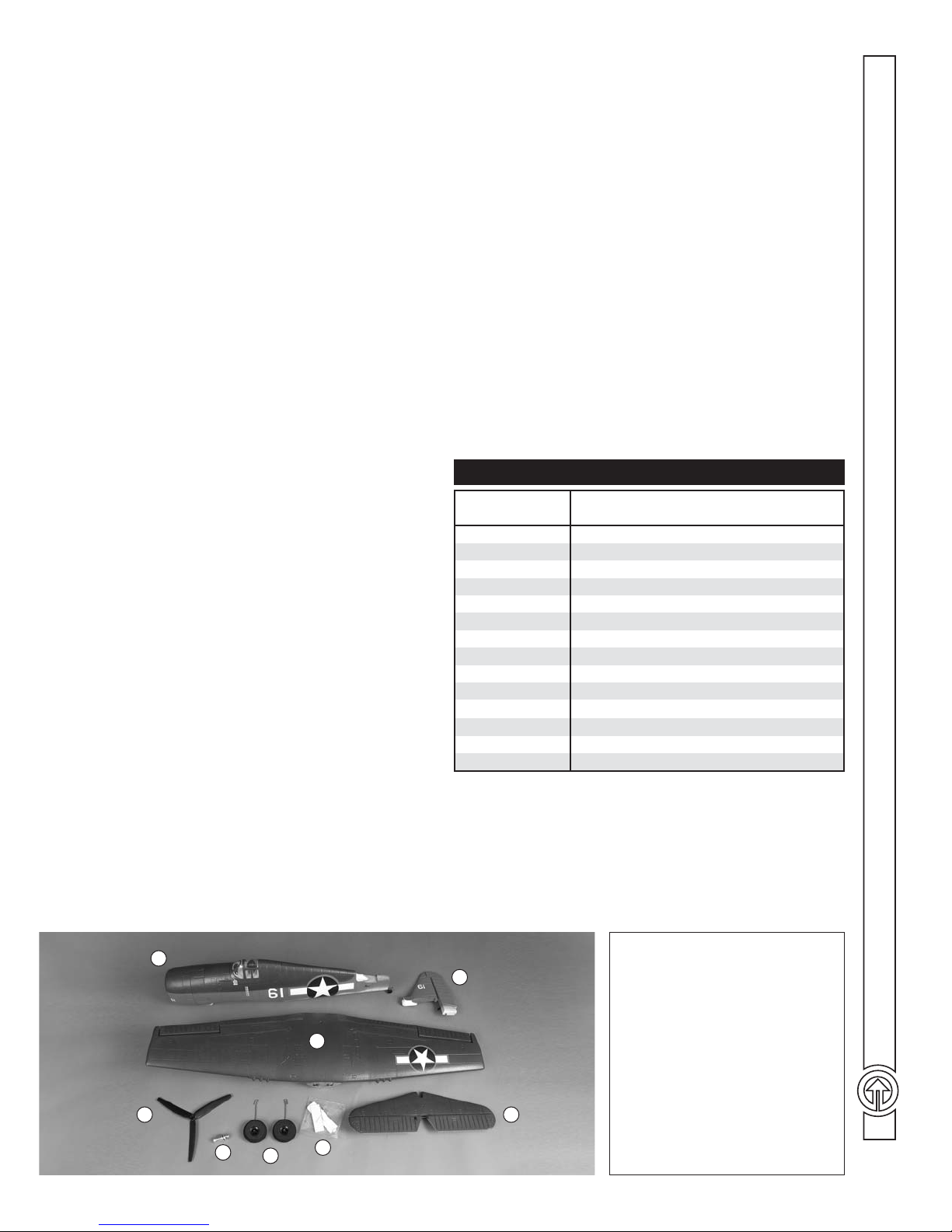
1
2
8
7
6
5
CONTENTS
3
––––––––––––––––––––––––––––––––––––
1. Fuselage, Cowl, Canopy Hatch
2. Wing
3. Vertical Stabilizer
4. Horizontal Stabilizer
5. Hardware Bag
6. Main Landing Gear
4
7. Propeller Hub
8. Propeller
3
Page 4

MAIN ASSEMBLY
NOTE: If you haven’t yet fi gured it out yet, the canopy hatch
is held to the fuselage with magnets at the rear and a tab at the
front. To remove the hatch, simply lift up on the aft end of the
hatch to disengage the magnets.
––––––––––––––––––––––
3. Connect the pushrods to the horns as shown.
❏
1. Fit the horizontal and vertical stabilizer (stab and fi n)
❏
together, then fi t them to the fuselage while keying the tail gear
into the rudder.
2. Fasten the stab and fi n assembly to the fuselage with the
❏
M3 x 40 screw.
4
4. Insert one, then the other main landing gear wires into
❏
the wing – the wire struts are positioned inboard of the wheels.
5. Guide the aileron servo wire through the hole in the bot-
❏
tom of the wing.
Page 5

6. Bolt the wing to the fuselage with the M6 x 50mm nylon
❏
wing bolt—don’t over tighten the bolt—just enough to securely
“snug” the wing up to the fuselage.
2. Use the included double-sided foam mounting strip to
❏
mount the receiver in the fuselage out of the way where it will
not interfere with installation and removal of the battery.
3. Without the propeller yet mounted, temporarily place the
❏
battery in the fuselage, turn on your transmitter and connect the
battery to the ESC to power the system up so you can check the
controls.
7. Apply the rougher, “hook” side of the included hook-and-
❏
loop material to the fuselage fl oor and the softer, “loop” side to
the battery.
FINAL ASSEMBLY
––––––––––––––––––––––
Hook Up the Controls
1. Connect the servo and ESC wires to the appropriate channels
❏
in your receiver.
4. Make sure all the controls respond in the correct direction
❏
according to your inputs and that all the control surfaces are
centered—if necessary, use the servo reversing in your transmitter
and adjust the pushrods in the screw-lock connectors to center
the controls. Whether or not you adjusted any pushrods, double-
check that the screw in all the screw-lock connectors are
tight and secure.
5
Page 6

Check the Control Throws
LESS control throw
Check the C.G.
The C.G. (center of gravity) has a great effect on the way the
Hellcat fl ies. If the C.G. is not correct the Hellcat could be too
stable (reacting too slowly to control inputs) or too instable
(reacting too quickly to control inputs) possibly causing a crash.
MORE control throw
MORE
control
throw
Raise the aft end of the fuselage so the wings and stab are level (or
nearly level). Measure the control surface throws and if necessary,
use the programming in your transmitter or change the location
of the pushrods in the servo arms or in the horns on the control
surfaces to get the recommended throws. Note that the throws
are measured at the widest part (front-to-back) of each surface:
If your radio does not have dual rates, we recommend setting the
throws halfway between the high and low rates.
THESE ARE THE RECOMMENDED CONTROL SURFACE THROWS:
HIGH RATE LOW RATE
LESS
control
throw
The Hellcat is designed to fl y with either an 1800mAh or
2100mAh 3S (11.7V) battery, but it could use a little help in
the C.G. department and will benefi t from the slightly heavier
2100mAh battery. The Hellcat should balance pretty much on
the recommended C.G. location with a 3S 2100mAh battery
positioned as far forward as it will go. It will still balance within
the recommended range with an 1800mAh battery all the way
forward, but to get it balanced directly on the recommended
point approximately .75 oz. [21g] may be required in the nose.
After checking the C.G., should you decide to stick an ounce
or so of ballast in the nose it is acceptable to do so directly to
the inside of the cowl. Eventually though the adhesive on the
double-sided foam tape on the back of most lead strips will
let go, so once you’ve fi nalized the amount of weight, attach
it more securely with a few drops of CA.
UP DOWN
7/16" [11mm]
13°
ELEVATORRUDDERAILERONS
RIGHT LEFT
3/4" [19mm]
19°
UP DOWN
1/2" [13mm]
17°
7/16" [11mm]
13°
3/4" [19mm]
19°
1/2" [13mm]
17°
6
UP DOWN
1/4" [6mm]
7°
RIGHT LEFT
1/2" [13mm]
13°
UP DOWN
3/8" [10mm]
12°
1/4" [6mm]
1/2" [13mm]
3/8" [10mm]
7°
13°
12°
1. With the battery disconnected, mount the propeller to the
❏
motor with the included collet adapter hub—for now the propeller
hub needs to be only fi nger tight (in case the cowl requires removal
for adding ballast to the nose later).
Page 7

2. If you haven’t done so already, install the battery—as
❏
previously suggested, start with the battery positioned as far
forward as it will go.
4. Lift the model upside-down with your fi ngertips on the
❏
recommended C.G. location you marked.
5. If necessary, shift the battery forward or aft or add stick-on
❏
lead ballast where required to get the model to balance.
Recommended
Starting C.G.
2-5/8" [67mm]
Back From Wing LE
at Fuselage Sides
2-5/8" [67mm] 2-5/8" [67mm]
3. The C.G. is to be marked on the top of the wing so that
❏
you can see where to position your fi ngers for lifting the model
for balancing, or better yet, so that you can actually feel the
marks. You could use a fi ne-point, felt-tip pen, or something
inconspicuous or removable such as pins inserted directly into
the foam that can be removed later. Whatever method you use,
mark the C.G. on the top of the wing where indicated.
Forward Limit:
2 - 1/4 " [ 57 mm ]
Aft Limit:
3" [76 mm]
6. Once the C.G. has been set, tighten the propeller hub using
❏
a small screwdriver as a torque bar.
MOTOR SAFETY PRECAUTIONS
Failure to follow these safety precautions may result in sever e
injury to yourself and others.
■ Seek the assistance of an experienced pilot if new to electric
motors.
■ Wear safety glasses whenever in the proximity of a spinning
propeller.
■ Do not operate the motor in an area of loose gravel or sand;
the propeller may throw such material in your face or eyes.
■ Keep spectators as well as your own face and body out of
the plane of rotation of the propeller.
■ Keep all loose clothing, long hair or any other loose objects
such as pencils or screwdrivers that may fall out pockets
away from the propeller.
–––––––
NOTE: The Hellcat may be fl own with the C.G. up to 3/8”
[10mm] ahead or 3/8” [10mm] behind the recommended
balance point. With the Hellcat balanced at the front of the range
it will be more stable, but less maneuverable and heavier due
to the ballast that may be required. With the Hellcat balanced
at the rear of the range the Hellcat will be more maneuverable,
but less stable and quicker to react to your control inputs.
7
Page 8

MOTOR/ESC OPERATION
Turning on the transmitter and operating the motor are intuitive
for most pilots who already have experience with electric motors,
but for those who may have little or no experience with electric
motors here are operating instructions for the ESC and motor
included with your Hellcat:
When ready to run up the motor, fi rst turn on the transmitter and
make sure the throttle stick is all the way down. Then connect
the battery to the ESC. The ESC will send a single, short pulse
to the motor, causing it to beep once (“beep”). To operate the
motor advance the throttle stick, hold it there momentarily, and
listen for another single beep (“beep”). Then return the throttle
stick all the way down.The motor will sound two more quick
beeps (“beep beep”). The next time the throttle stick is advanced,
the propeller will turn. You are now ready to fl y.
If the transmitter is not turned on before the battery and ESC
are connected (so the receiver is not receiving a signal), the
motor will beep rapidly (“beep beep beep beep…”) until either
the battery is disconnected or the transmitter is turned on. Then,
the ESC will resume its normal arming sequence.
If, when the battery is connected to the ESC, the throttle stick
is not all the way down the motor will beep steadily (“beep,”
“beep,” “beep…”) until either the battery is disconnected or the
throttle stick is returned to the off position. This time the ESC
will resume its normal arming sequence.
–––––––––––––
much you have available. Compare the capacity used to 80% of
your battery’s capacity and adjust your fl ight time accordingly.
FOR EXAMPLE: If using the recommended 2100mAh battery,
your target capacity available is 1680mAh (2100mAh x .8). If you
fl y for fi ve minutes and it takes 1200mAh to recharge your battery,
you still had 480mAh to go, so adjust your timer to increase your
fl ight time accordingly until you reach your 1680mAh target.
(You could also divide 1200mAh by fi ve minutes to fi gure a
current consumption rate of 240mAh/minute. Divide 1680mAh
by 240mAh/minute to conclude that you can fl y for 7 minutes.)
It’s also a great idea to use a LiPo battery checker (HCAP0275)
to check the battery before each fl ight (to make sure you haven’t
inadvertently grabbed a discharged battery) and to check the
battery after fl ight to make sure you haven’t over discharged
your battery by fl ying too long. A safe, conservative, minimum
voltage is 3.65V – 3.7V per cell right after a fl ight.
FLYING
The Hellcat doesn’t exhibit any particular characteristics that you
need to be made aware of ahead of time, other than it is a slightly
“draggy” airframe that will benefi t from a few clicks of throttle
while dragging it in for a landing—just let the Hellcat settle and
it will touch down smoothly. Then, cut the throttle.
Flying “normally,” the Hellcat consumes approximately 250mAh/
minute which should provide approximately 6-1/2 to 7 minutes of
motor run time on a 2100mAh battery—of course, the run time
you can expect depends on many factors such as the condition
of your batteries, your fl ying style and even the wind conditions
(fl ying on windy days seems to use more power than fl ying on
calm days).
To fi nd out for yourself how long you can fl y, set your timer to
a conservative 5 minutes. Fly until the timer sounds, then land.
Use a charger with a digital display to fi nd out how much capacity
it took to recharge the battery (indicating how much capacity
was used). To avoid over discharging your LiPos, likely causing
reduced performance, the target is to use 80% of your battery’s
capacity, so multiply your battery’s capacity by .8 to fi nd out how
–––––––––––––––––––––––––––––––––
Name
Address
City, State, Zip
AMA Number
Phone Number
REPAIRS
Parts damaged beyond repair can be purchased separately. The
full replacement part list is printed in the front of the manual on
page 3. Often though, parts can be repaired and you can get your
Hellcat back into the air with a little glue and ingenuity.
The Hellcat is made from injection-molded EPO (expanded
polyolefi n) foam which can be glued with just about anything.
Most people use regular CA. With CA no clamping is required,
but some prefer softer, more fl exible adhesives such as white
glue or canopy glue. These kinds of glues will require clamps
or tape to hold the parts together while the glue dries.
One fi nal note about fl ying your model. Have a goal or fl ight plan
in mind for every fl ight. This can be learning a new maneuver(s),
improving a maneuver(s) you already know, or learning how
the model behaves in certain conditions (such as on high or low
rates). This is not necessarily to improve your skills (though it is
never a bad idea!), but more importantly so you do not surprise
yourself by impulsively attempting a maneuver and suddenly
fi nding that you’ve run out of time, altitude or airspeed. Every
maneuver should be deliberate, not impulsive. For example, if
you’re going to do a loop, check your altitude, mind the wind
direction (anticipating rudder corrections that will be required to
maintain heading), remember to throttle back at the top, and make
certain you are on the desired rates (high/low rates). A fl ight plan
greatly reduces the chances of crashing your model just because
of poor planning and impulsive moves. Remember to think.
Have a ball! But always stay in control and fl y in a safe manner.
–––––––––––––––––––––––––––––––
This model belongs to:
8
GOOD LUCK AND GREAT FLYING!
 Loading...