

Page 1
INSTRUCTION MANUAL
®
Tower
Hobbies®
guarantees
this kit to be
free from defects
in both material and
workmanship at the
WARR ANT Y
date of purchase. This
warranty does not cover any
component parts damaged by
use or modication. In no case shall
Tower Hobbies’ liability exceed the
original cost of the purchased kit. Further,
Tower Hobbies reserves the right to change
or modify this warranty without notice.
In that Tower Hobbies has no control over the nal
assembly or material used for nal assembly, no
liability shall be assumed nor accepted for any damage
resulting from the use by the user of the nal user-assembled
product. By the act of using the user-assembled product, the
user accepts all resulting liability.
If the buyer is not prepared to accept the liability associated with the
use of this product, the buyer is advised to return this kit immediately in
new and unused condition to the place of purchase.
To make a warranty claim send the defective part or item to Hobby Services at
the address below:
Hobby Services • 3002 N. Apollo Dr. Suite 1 • Champaign IL 61822 • USA
Include a letter stating your name, return shipping address, as much contact information as
possible (daytime telephone number, fax number, e-mail address), a detailed description of
the problem and a photocopy of the purchase receipt. Upon receipt of the package the problem
will be evaluated as quickly as possible.
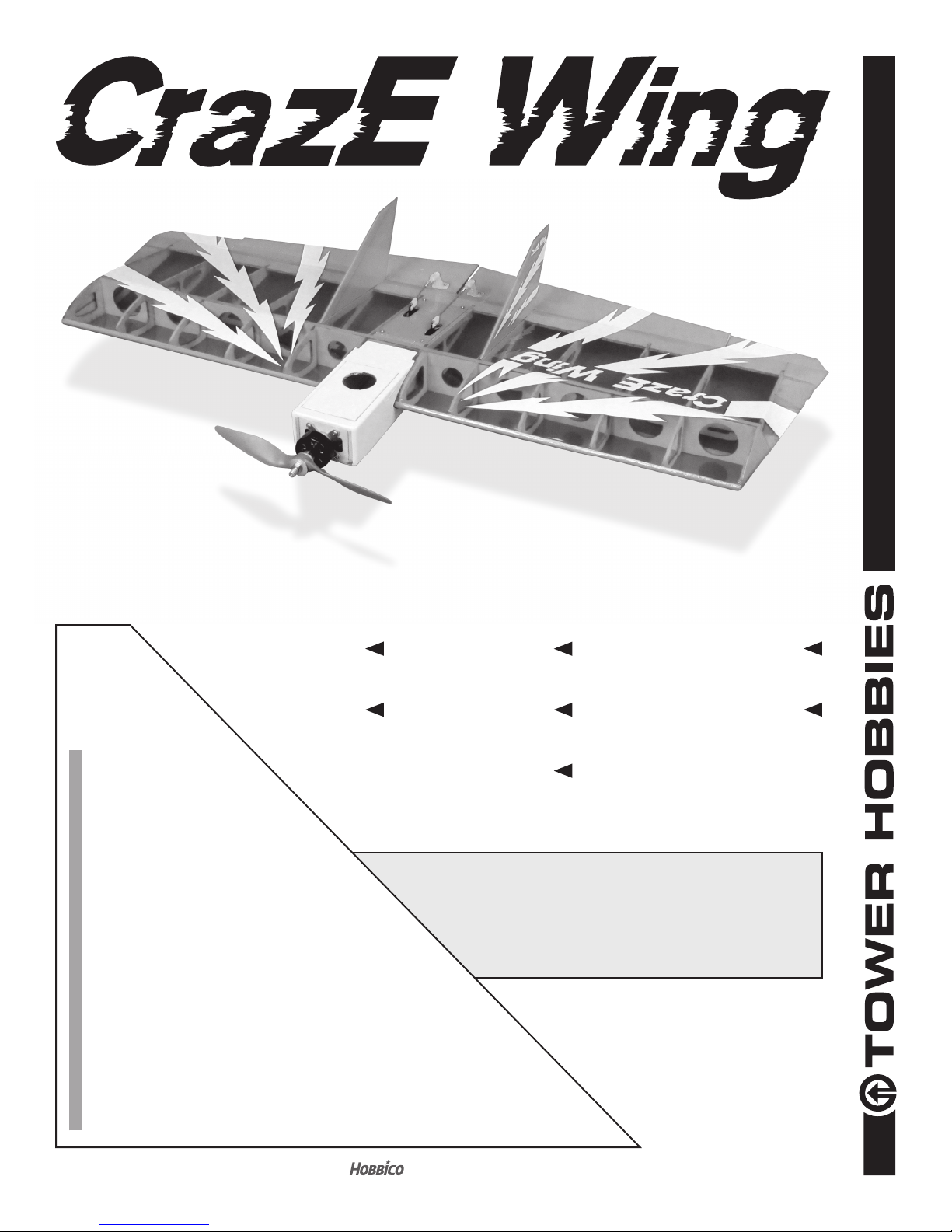
WINGSPAN
35.5 in [ 900 mm]
MOTOR
30-35-1000
Brushless
Electric
LENGTH
18. 75 in [ 476 mm ]
WING AREA
409 sq in [26.4 dm2]
WEIGHT
20 –23 oz [567–652g]
READ THROUGH THIS MANUAL
BEFORE STARTING CONSTRUCTION.
IT CONTAINS IMPORTANT INSTRUCTIONS
AND WARNINGS CONCERNING THE
ASSEMBLY AND USE OF THIS MODEL.
WING LOADING
7. 0 – 8. 1 oz / f t2 [21.3– 24.79 g/dm2]
RADIO
3-Channel, Flying Wing Programmable
Two Mini Servos with
at least 38g of torque.
TOWER HOBBIES
Champaign, Illinois
(217) 398-8970 ext. 5
airsupport@hobbico.com
®
®
© 2016 Tow e r H ob b ie s .
A subsidiary of Hobbico, Inc.
TOWA2010
1
Page 2

TABLE OF CONTENTS
INTRODUCTION . . . . . . . . . . . . . . . . . . . . . . . . . . . . . . . . 2
Academy of Model Aeronautics . . . . . . . . . . . . . . . . . 2
SAFETY PRECAUTIONS . . . . . . . . . . . . . . . . . . . . . . . . . 2
ADDITIONAL ITEMS REQUIRED . . . . . . . . . . . . . . . . . . 3
Radio Components . . . . . . . . . . . . . . . . . . . . . . . . . . . 3
Propellers. . . . . . . . . . . . . . . . . . . . . . . . . . . . . . . . . . . 3
Battery and Charger . . . . . . . . . . . . . . . . . . . . . . . . . . 3
Adhesives and Building Supplies . . . . . . . . . . . . . . . . 3
Hardware and Accessories . . . . . . . . . . . . . . . . . . . . . 3
KIT INSPECTION . . . . . . . . . . . . . . . . . . . . . . . . . . . . . . .4
CONTENTS . . . . . . . . . . . . . . . . . . . . . . . . . . . . . . . . . . . . 4
PREPARATION . . . . . . . . . . . . . . . . . . . . . . . . . . . . . . . . . 5
ASSEMBLY . . . . . . . . . . . . . . . . . . . . . . . . . . . . . . . . . . . . 5
Install the Servos . . . . . . . . . . . . . . . . . . . . . . . . . . . . . 5
INTRODUCTION
If you are looking to put some excitement in your ying, the
CrazE Wing is for you. It can go from slow and mild to all
out wild in a second. The CrazE Wing assembles quick and
easy. You will be ying in just a few hours. So let’s get the
components needed to nish the plane and get started.
For the latest technical updates or manual corrections for
the CrazE Wing ARF visit the Tower Hobbies web site at
towerhobbies.com and visit the page for the CrazE Wing. If
there is new technical information or changes to this model
a “tech notice” box will appear on the page.
As a new owner of an unmanned aircraft system (UAS), you
are responsible for the operation of this vehicle and the safety
of those around you. Please contact your local authorities
to nd out the latest rules and regulations.
In the United States, please visit:
Install the Motor . . . . . . . . . . . . . . . . . . . . . . . . . . . . . . 8
Check the Control Directions . . . . . . . . . . . . . . . . . . . 8
Apply the Decals . . . . . . . . . . . . . . . . . . . . . . . . . . . . 10
Check the C.G. (Center of Gravity) . . . . . . . . . . . . . . 10
PREFLIGHT . . . . . . . . . . . . . . . . . . . . . . . . . . . . . . . . . . . 10
Identify Your Model . . . . . . . . . . . . . . . . . . . . . . . . . . 10
Charge the Batteries . . . . . . . . . . . . . . . . . . . . . . . . . 11
Ground Check and Range Check . . . . . . . . . . . . . . . 11
ELECTRIC MOTOR SAFETY PRECAUTIONS . . . . . . . 11
FLIGHT TIPS . . . . . . . . . . . . . . . . . . . . . . . . . . . . . . . . . . 12
Takeoff . . . . . . . . . . . . . . . . . . . . . . . . . . . . . . . . . . . . 12
Flight . . . . . . . . . . . . . . . . . . . . . . . . . . . . . . . . . . . . . 12
Landing . . . . . . . . . . . . . . . . . . . . . . . . . . . . . . . . . . . 12
sites to help you get started the right way. There are over
2,500 AMA chartered clubs across the country. Contact the
AMA at the address or toll-free phone number that follows.
Academy of Model Aeronautics
5151 East Memoria l Drive
Muncie, IN 47302-9252
Tele. (800) 435-9262
Fax (765) 741-0057
Or via the Internet at: www.modelaircraft.org
IMPORTANT: Two of the most important things you can do
to preserve the radio controlled aircraft hobby are to avoid
ying near full-scale aircraft and avoid ying near or over
groups of people.
SAFETY PRECAUTIONS
Protect Your Model, Yourself & Others…
Follow These Important Safety Precautions
knowbeforeyou y.org faa.gov/uas
Academy of Model Aeronautics
We urge you to jo in the AMA (Academy of Model Aeronautics)
and a local R/C club. The AMA is the governing body of model
aviation and membership is required to y at AMA clubs.
Though joining the AMA provides many bene ts, one of the
primary reasons to join is liability protection. Coverage is not
limited to ying at contest s or on the cl ub eld. It even applies
to ying at public demonstrations and air shows. Failure to
comply with the Safety Code (excerpts printed in the back of
the manual) may endanger insurance coverage. Additionally,
training programs and instructors are available at AMA club
1. Your CrazE Wing ARF should not be considered a
toy, but rather a sophisticated, working model that
functions very much like a full-size airplane. Because
of its performance capabilities, the CrazE Wing ARF, if
not assembled and operated correctly, could possibly
cause injury to yourself or spectators and damage to
property.
2. You must assemble the model according to the
instructions. Do not alter or modify the model, or use
larger than recommended power systems, as doing
so may result in an unsafe or un yable model. In a few
cases the instructions may differ slightly from the photos.
In those instances the written instructions should be
considered as correct.
2
Page 3

3. You must take time to build straight, true and strong.
4. You must use an R/C radio system that is in rst-class
condition.
5. You must correctly install all R/C and other components
so that the model operates correctly on the ground and
in the air.
6. You must check the operation of the model before every
ight to insure that all equipment is operating and that
the model has remained structurally sound. Be sure to
check clevises or other connectors often and replace
them if they show any signs of wear or fatigue.
7. If you are not an experienced pilot or have not own this
type of model before, we recommend that you get the
assistance of an experienced pilot in your R/C club for
your rst ights. If you’re not a member of a club, your
local hobby shop has information about clubs in your
area whose membership includes experienced pilots.
We, as the kit manufacturer, provide you with a top quality,
thoroughly tested kit and instructions, but ultimately the
quality and yability of your nished model depends
on how you build it; therefore, we cannot in any way
guarantee the performance of your completed model,
and no representations are expressed or implied as to the
performance or safety of your completed model.
REMEMBER: Take your time and follow the instructions
to end up with a well-built model.
ADDITIONAL ITEMS REQUIRED
Propellers
❍ 3S LiPo – APCQ4118 9x6E or APCQ4119 9x7.5E
❍ 4S LiPo – APCQ4116 8x8E
Battery and Charger
❍ A 3S to 4S 1800mAh – 2200mAh LiPo battery is required
to power the CrazE Wing ARF.
❍ ElectriFly 3S 1800mAh 30C (GPMP0855)
❍ ElectriFly 3S 2200mAh 30C (GPMP0861)
❍ FlightPower 3S 1800mAh 50C (FPWP5183)
❍ FlightPower 3S 2200mAh 30C (FPWP3223)
❍ FlightPower 3S 2200mAh 50C (FPWP5223)
❍ ElectriFly 4S 2200mAh 30C (GPMP0862)
❍ FlightPower 4S 2200mAh 30C (FPWP3224)
Most modelers may already have a suitable LiPo charger,
but for those that do not, the Duratrax Onyx 235 AC/DC
Advanced Peak Charger (DTXP4235) is one of the suitable
chargers recommended. The Onyx charger is perfect for 3
and 4S batteries used with the CrazE Wing ARF and may
be powered either by an external DC power source (such
as a 12V battery), or a 110V AC outlet. The Onyx also has
an adjusta ble charge ra te to charg e yo ur batte ries in as lit tle
as a half-hour or less (depending on the condition of your
batteries and manufacturer’s speci ed charge rate). The
Onyx can also charge larger batteries and batteries other
than LiPo, so it is a versatile charger you can grow into. The
235 also has an LCD digital display screen, so you can see
how much capacity it took to recharge the battery (required
for monitoring the condition of your batteries and calculating
how long you can y).
Radio Components
A 3-channel radio with elevon (sometimes called delta), an
Electronic Speed Control and two mini servos with 38oz. of
torque are required to y the CrazE Wing ARF. The Tactic
TTX650 6-channel or Futaba 6J 6-channel radio system are
great low cost radio systems perfect for the CrazE Wing ARF.
❍ TACJ2650 Tactic TTX650 6-channel SLT Computer
Trans m it ter
OR
❍ FUTK6000 Futaba 6J 6-channel S-FHSS System
❍ (2) FUTM0415 Futaba S3115 Micro Precision Servo
OR
❍ (2) FUTM0034 Futaba S3102 Aircraft Micro Metal
Gear Servo
❍ TOWG2000 Tower Hobbies Electric Motor 30-35-
1000
❍ FLZA6612 Flyzone 40A Select Scale ESC
❍ FLZA6614 Flyzone Prop Adapter
❍ GPMQ4480 1" x 6" Velcro
Adhesives and Building Supplies
❍ Tower Hobbies 6-minute Epoxy (TOWR3806)
❍ Mixing Sticks (50, GPMR8055)
❍ Mixing Cups (GPMR8056)
❍ Tower Hobbies Build-It CA Thin Glue (TOWR3800)
❍ Denatured Alcohol (for epoxy clean-up)
❍ Masking Tape
❍ 5/64" (2mm) drill bit
❍ Drill
❍ Phillips head screwdriver
❍ Wire Cutters
❍ Pliers
❍ Stick-on segmented weights (GPMQ4485)
❍ Medium T-pins (HCAR5150)
❍ CG Machine (GPMR2400)
❍ Paper Towels
Hardware and Accessories
❍ 21st Century Sealing Iron (COVR2700)
❍ 21st Century Hot Sock (COVR2702
3
Page 4
KIT INSPECTION
Before starting to build, take an inventory of this kit to make
sure it is complete, and inspect the parts to make sure they
are of acceptable quality. If any parts are missing or are not of
acceptable quality, or if you nee d assistance with assembly,
contact Order Assistance.
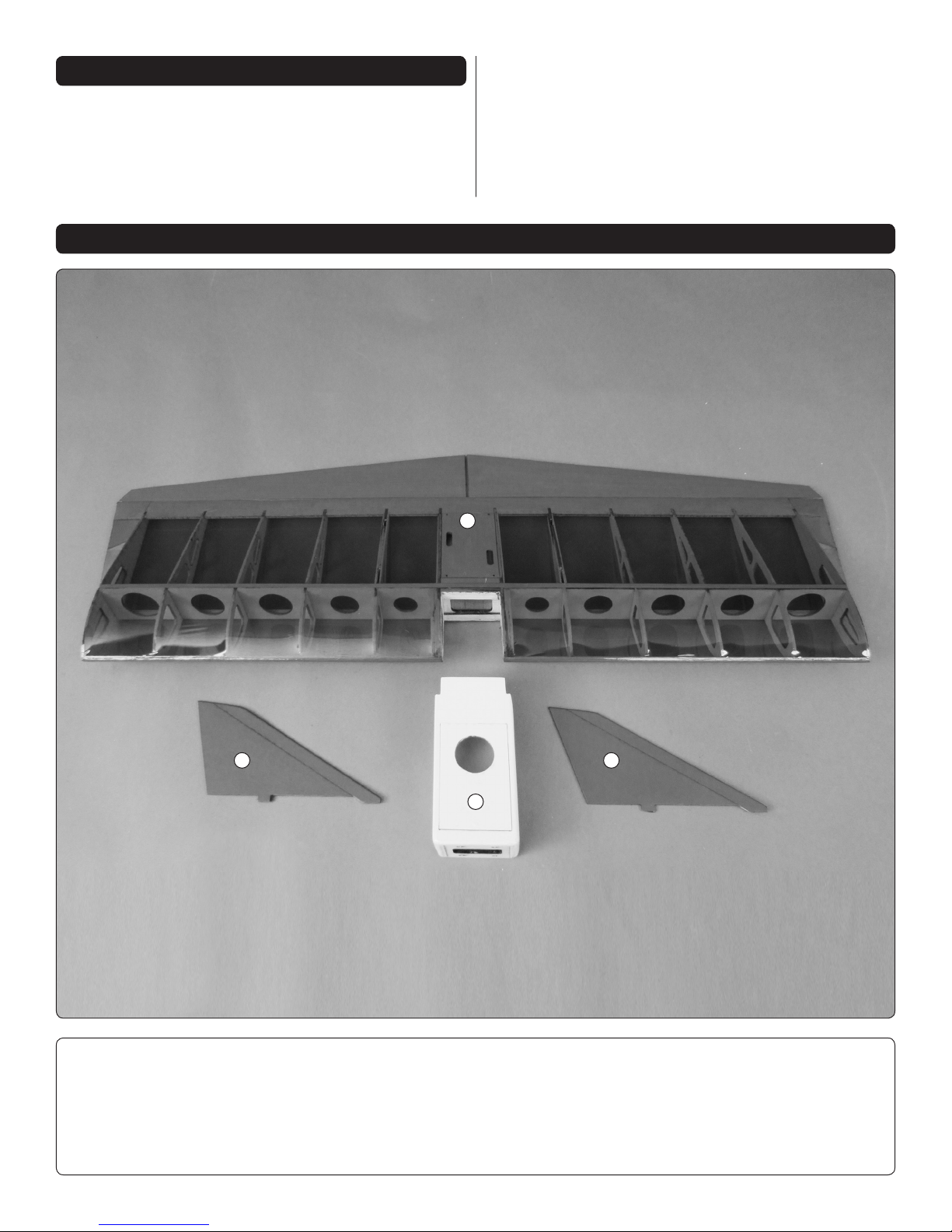
CONTENTS
Order Assistance Ph: (800) 637-6050
Fax: (217) 398-7721
E-maiI: airsupport@towerhobbies.com
1
1. Wing
2. Motor/Battery Box
3. Vertical Fin
2
Hardware not shown:
(2) Large nylon control horn
(2) Nylon control horn back plate
(2) Nylon clevis
(2) Nylon Faslink
(2) Silicone clevis keeper
4
33
(2) 2-56 x 6" [152 mm] wire pushrod
(4) Hardwood servo mounting blocks
(4) 2-56 x 3/8 [ 9.5 mm] Machine Screw
(4) #2 x 3/8" [9.5mm] Sheet Metal Screw
(4) 3 x 10mm Machine Screw
Page 5

PREPARATION
Use a covering iron set to about 300° F with a covering sock
to go ove r the mod el, tighte ning the coveri ng where neces sary.
NOTE: This covering material requires less heat than you
may be used to. Excessive heat will cause the covering to pull
away from the seams or may even cause the parts to bend.
4. Position the servos so that the servo arms are centered
❏
in the openings of the radio compartment hatch.
ASSEMBLY
IMPORTANT: When installing sheet metal screws into
wood, rst drill a pilot hole, install the screws, remove the
screws and harden the threads in the wood with thin CA,
then reinstall the screws.
Install the Servos
1. Install the grommets in the two aileron servos.
❏
2. Cut the two servo arm gauges from the back of this
❏
instruction manual.
3. Follow your transmitter instructions for setting up a
❏
delta wing plane.
a. Connect the servos to the appropriate channels on the
receiver and temporarily connect the ESC to the receiver.
b. Switch on the transmitter and connect the motor battery
to the ESC.
c. Center the trims on the transmitter.
d. Using the servo arm gauges, install a servo arm on both
servos as shown.
e. Unplug the motor battery and switch off the transmitter.
5. Glue the servo mounting blocks.
❏
6. Secure the servos.
❏
5
Page 6

7. Install the servo hatch.
❏
8. Install the nylon clevis.
❏
9. Attach the clevis.
❏
10. Install the control horn.
❏
11. Cut out the re ex gauge from the back of this instruction
❏
manual.
6
Page 7

12. Use a piece of masking tape to hold the elevon
❏
in position.
15. Attach the clevis in the 4th hole of the control horn.
❏
Secure the L-bend to the servo arm with a Faslink.
13. Mark the pushrod.
❏
14. Make an L-bend at the mark.
❏
16. Install the pushrod and control horn on the
❏
second elevon.
17. Mount the receiver in the front of the servo compartment
❏
wi th Vel cro (no t in cluded). Sec ure the antenna s following the
manufacturer’s recommendations.
7
Page 8

Install the Motor
FULL
THROTTLE
BOTH ELEVONS
MOVE DOWN
3-CHANNEL
RADIO SET UP
(STANDARD MODE 2)
RIGHT ELEVON
MOVES UP,
LEFT ELEVON
MOVES DOWN
1. Use epoxy to glue the motor box on the front of the wing.
❏
Check the Control Directions
It will be easier to adjust the control throws before installing
the two vertical ns.
2. Install the motor. If using a different motor than we
❏
recommend, use the existing holes to locate new holes and
re-use the blind nuts by knocking them out.
1. With the transmitter on and the motor battery plugged
❏
into the ESC, make sure the elevons move correctly as shown
in the diagram.
NOTE: Use the servo reversing function to change the servo
direction if needed. If changing the servo reversing function
for one operation causes the other operation to be reversed,
switch the two servo leads where they plug into the receiver.
Then, use the reversing function to correct the servo direction.
3. Connect the ESC to the motor and the receiver. Switch
❏
on the transmitter and plug the motor battery into the ESC.
Check that the motor is rotating in the correct direction.
The ESC can be attached to the side of the motor box with
Velcro (not included).
Use a ruler to measure and set the control throw of the
elevons as indicated in the chart that follows.
NOTE: The throws are measured at the widest part of the
elevons.
8
Page 9

These are the recommended control surface throws:
HIGH RATE
Up
ELEVATOR
AILERONS
60% exponential was used on the high rate.
30% exponential was used on the low rate.
IMPORTANT: The CrazE Wing has been extensively own
and tested to arrive at the throws at which it ies best.
Flying your model at these throws will provide you with
the greatest chance for a successful rst ight. If, after
you have become accustomed to the way the CrazE Wing
ies, you would like to change the throws to suit your taste
that is ne. However, too much control throw could make
the model dif cult to control, so remember, “more is not
always better.”
3/4"
[19mm]
16°
Up
1-7/8"
[47.5mm]
34°
Down
3/4"
[19mm]
16°
Down
1-7/8"
[47.5mm]
34°
LOW RATE
Up
1/2"
[12.5 mm]
10°
Up
3/4"
[19mm]
16°
Down
1/2"
[12.5 mm]
10°
Down
3/4"
[19mm]
16°
2. Use a T-pin to poke several holes in the tabs of the
❏
vertical ns or carefully trim the covering off. Do not cut
into the balsa.
!!! WARNING !!!
Set the Failsafe
With electric planes, once the motor battery is connected
to the ESC the motor can come on at anytime causing
damage or serious injury. If the failsafe is not set and
the transmitter is switched off before the motor battery
is disconnected, the motor could come on. Review the
instructions included with your radio system for setting
the failsafe.
Setting the Tactic TR625 receiver failsafe:
1. Switch on the transmitter and connect the motor
❑
battery to the ESC.
2. Make sure the throttle stick is down.
❑
3. Press and hold the “Link” button on the receiver
❑
until the red LED goes out and then release the button
and the red LED should come back on.
4.
Check the failsafe operation. To arm the motor the
❑
throttle stick must be in the down position. If the throttle
stick is not, the motor will beep. Once the throttle stick
is moved to the down position the motor is ready to run.
With the transmitter switched on and the motor battery
connected, move the throttle stick so that the motor is
running slowly. Switch off the transmitter and the motor
will stop if the failsafe is set correctly. If it does not stop,
repeat the failsafe setting procedure.
3. Use epoxy to glue the vertical ns in the wing.
❏
4. Install the collet type prop adapter.
❏
9
Page 10

5. Install the propeller. Tighten the prop nut.
❏
6. Apply Velcro to the bottom of the motor box and the
❏
motor battery.
7. Place the motor battery in the motor box. DO NOT
❏
connect the battery to the ESC.
Apply the Decals
Check the C.G. (Center of Gravity)
DO NOT OVERLOOK THIS IMPORTANT PRCEDURE.
A model that is not properly balanced will be unstable and
possibly un yable.
The CG is 1-1/4" (31mm) to 1-7/8" (47mm) from leading edge.
1. Mark the C.G. range on the top of the motor box.
❏
1. Be certain the model is clean and free from oily
❏
ngerprints and dust. Prepare a dishpan or small bucket
with a mixture of liquid dish soap and warm water – about
½ teaspoon of soap per gallon of water. Submerse one of
the decals in the solution and peel off the paper backing.
Note: Even though the decals have a “sticky-back” and are
not the water transfer type, submersing them in soap and
water allows accurate positioning and reduces air bubbles
underneath.
2. Position the decal on the model where desired. Holding
❏
the decal down, use a paper towel to wipe most of the water
away.
3. Use a piece of soft balsa or something similar to
❏
squeegee remaining water from under the decal. Apply the
rest of the decals the same way.
2. With the plane ready to y, motor battery installed, use
❏
a Great Planes C.G. Machine or apply narrow (1/16" [2mm])
strips of tape at the front and rear C.G. locations so you will
be able to feel them when lif ting the model with your ngers
to check the C.G. location. Do not at any time balance the
model outside this C.G. range.
3. If the CrazE Wing does not balance within the
❏
recommended range, reposition the battery to get the model
to balance. Once the correct battery location has been
determined, mark the location on the inside of the fuselage
so that the battery can be installed in the same location
every time. If the plane still does not balance after moving
the battery, use Great Planes Stick-on Segmented weights
to balance the plane.
10
Page 11

PREFLIGHT
ELECTRIC MOTOR SAFETY PRECAUTIONS
Identify Your Model
You should always have your name, address, telephone
number, AMA and FAA number on or inside your model. It is
required at all AMA R/C club ying sites and AMA sanctioned
ying events. Fill out the identi cation tag on page 12 and
place it on or inside your model.
Charge the Batteries
Follow the battery charging instructions that came with your
radio system to charge the batteries. You should always
charge your transmitter batteries the night before you go
ying and at other times as recommended by the radio
manufacturer.
CAUTION: Unless the instructions that came with your
radio system state differently, the initial charge on a new
transmitter battery should be done for 15 hours using the
slow-charger that came with the radio system. This
will “condition” the batteries so that the next charge may
be done using the fast-charger of your choice. If the initial
charge is done with a fast-charger, the batteries may not
reach their full capacity and you may be ying with batteries
that are only partially charged.
Ground Check and Range Check
Follow the radio manufacturer’s instructions to ground check
the operational range of your radio before the rst ight of
the day. This should be done once with the motor off and
once with the motor running at various speeds. If the control
surfaces do not respond correctly, do not y. Find and
correct the problem rst. Look for loose servo connections or
br oke n wi res, corroded wir es or connectors o r try relocating
the receiver and antennas.
ALWAYS Wear safety glasses whenever running motors.
ALWAYS Keep your face and body as well as all spectators
away from the plane of rotation of the turning propeller.
ALWAYS Keep loose clothing and objects such as pencils
or screwdrivers that may fall out of a shirt or jacket pockets
away from the prop.
NEVER touch the motor during or right after operation. The
motor gets HOT!
ALWAYS remove the propeller from the plane when working
on it if the motor batteries will be connected.
ALWAYS remove the motor batteries from the plane when
charging.
ALWAYS follow the charging instructions included with your
charger for charging LiPo batteries. LiPo batteries can cause
serious damage if misused.
ALWAYS make su re t he fail s afe is set on you r radio to prevent
the motor from starting if the signal is lost. Once the motor
batteries are connected, the motor can start at anytime.
ALWAYS unplug the motor batteries rst.
NEVER switch off the transmitter with the motor batteries
plugged in.
WARNING: Read the entire instruction sheet included
with your motor batteries. Failure to follow the instructions
could cause permanent damage to the batteries and its
surroundings and cause bodily harm.
ALWAYS use an LiPo approved charger.
NEVER use a NiCd/NiMH peak charger to charge a LiPo
battery.
NEVER charge in excess of 4.20V per cell.
ALWAYS charge through the “charge” lead.
NEVER charge through the “discharge” lead.
NEVER ch arge at c urre nts grea ter than 1C unless the bat tery
is rated for a higher charge rate.
11
Page 12

ALWAYS set the charger’s output volts to match the battery
volts.
ALWAYS charge a LiPo battery in a reproof location.
NEVER trickle charge a LiPo battery.
NEVER allow the battery temperature to exceed 150 degrees
F (65 degrees C).
NEVER discharge below 2.7V per cell
NEVER place the battery or charger on combustible materials
or leave it unattended during charge or discharge.
ALWAYS KEEP OUT OF THE REACH OF CHILDREN.
NEVER charge the battery in the plane.
ALWAYS remove the battery from the plane after a crash.
Set it aside in a safe location for at least 20 minutes. If the
battery is damaged in the crash it could catch re.
ALWAYS move the battery to a safe location, preferably
outside, if it starts to swell. Place it in a bucket and cover
it with sand. Never use water to try and put out a LiPo re.
FLIGHT TIPS
With the throws set on low rate, slowly advance the throttle
while having your assistant launch the plane into the wind at
a nose-level or slightly nose –up attitude. Gain some altitude,
keeping the wings level. Once at a comfortable altitude, trim
the elevons for straight and level ight. Once the plane has
been trimmed future hand launches will be easy.
Flight
It is a good ide a to have a timer se t on you r transmitte r, wrist
watch or cell phone. We found that the plane can y for
5-minutes or more on a 4S 2200mAh LiPo battery. Set the
timer for 4-minutes for the rst few ights. When recharging
the battery note how much capacity was put back into the
battery. To maintain the performance of LiPo batteries no
more than 80% of the capacity should be drained from the
battery on a ight. Adjust the timer as needed.
The plane ies well at slow speed, but the fun is at high
speeds. The plane can be own at full throttle and full aileron
or elevator can be applied. Make sure you have plenty of
altitude when you do this the rst time. Rolls are very fast
and losing orientation is easy.
Takeof f
Before the rst ight make sure all the controls are moving
in the correct direction. For the rst ight it is best to have
an assistant hand launch the plane. This will allow you to
concentrate on trimming the plane. Have your assistant hold
the plane by the motor box in front of the wing leading edge.
This model belongs to:
Name
Landing
As said before, the plane ies well at slow speeds. When
coming in for a landing, point the plane into the wind, reduce
the throttle and let the plane settle in. Just before touch-down
add a small amount of up elevator to air.
Address
City, State, Zip
Phone Number
AMA Number
FAA Number
ID Tag
12
 Loading...