

Page 1

1
®
FEATURES
SLT TECHNOLOGY, TX-R, & COMPATIBLE RECEIVERS
It is strongly recommended to completely read this manual before use!
Damage resulting from misuse or modification will void the warranty.
•
Power LED with low voltage warning
•
Wireless training function
•
Digital trims for aileron, elevator, rudder
•
Gimbals with smooth ball-bearing feel
•
Charge jack for optional rechargeable batteries
•
Failsafe in the included receiver
This radio includes SLT technology to ensure a strong,
clear, frequency-hopping 2.4GHz signal is emitted, and
that your compatible receiver accepts a signal only from
your transmitter. Linking the included Tower Hobbies
brand receiver is accomplished by the simple push of a
button. This radio is also compatible with all transmitterready aircraft bearing the Tx-R™ logo, and Tactic and other brand receivers
having the SLT* protocol.
* Make sure optional receivers have the genuine SLT protocol before use with this radio.
Page 2
2
PREFLIGHT PREPARATIONS
Pay special attention to all precautions and warnings to ensure the safest operation.
This radio system is intended for sport and recreational fl ying of R/C models only.
Tower Hobbies is not responsible for incidental damage or personal harm resulting
from improper usage or unauthorized alteration of this product. Physical modifi cations
of any component in this system will void the warranty. For best results, make sure
all batteries are new (if alkalines) or fully charged (if rechargeable). Connect servos
to the receiver and try to adjust the radio on the workbench while reading along with
this instruction manual to understand all functions.
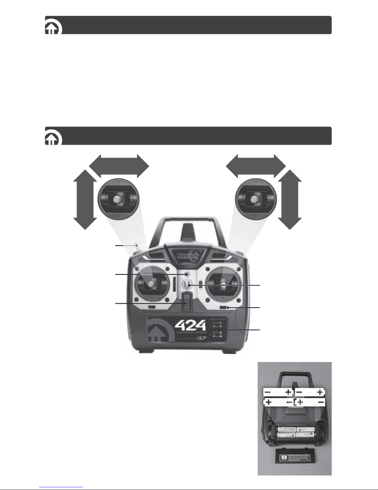
TRANSMITTER
Reversing Switches
On/Off Switch
Trim Lever
Power Indicator LED
Neck Strap Eyelet
Trainer Switch
%
,
%
6
!
4
/
2
AILERON
4
(
2
/
4
4
,
%
RUDDER
INPUT POWER: This transmitter (Tx) requires four “AA”
batteries. Non-rechargeable 1.5V alkaline or rechargeable
1.2V nickel-cadmium (NiCd) or nickel-metal hydride
(NiMH) cells can be used (not included). Do not mix old
and new cells, or mix non-rechargeable alkaline cells with
rechargeable NiCd or NiMH cells, etc. See the Accessories
section at the end of this manual for optional batteries.
To install the batteries, slide open the battery door. Install
the batteries as shown in the diagram. Make sure to note
the proper polarities on each cell. Close the battery door.
Page 3
3
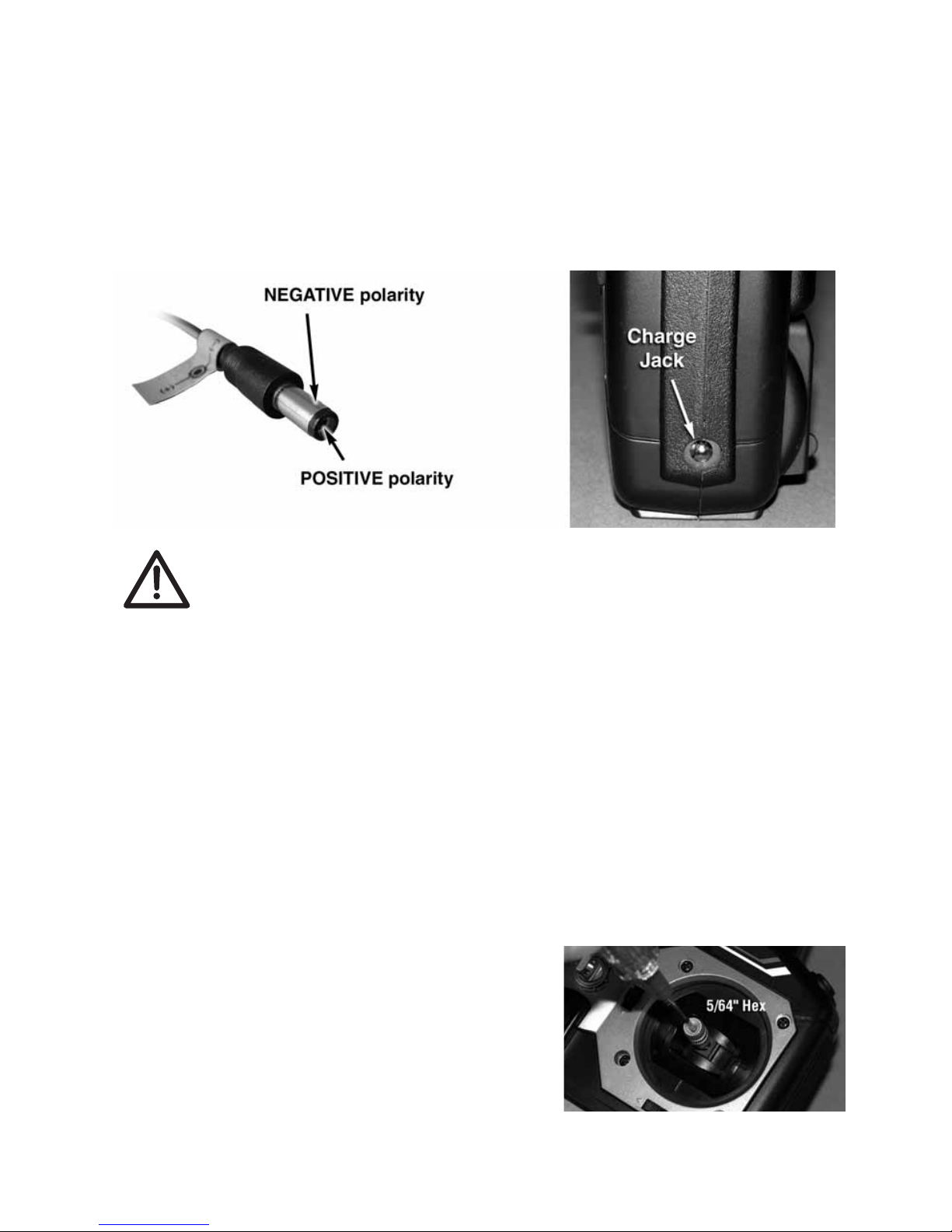
CHARGE JACK: A built-in charge jack is included for recharging of NiCd or NiMH
rechargeable batteries. This jack can accept charge leads designed for Tactic brand
transmitters, with the center pin being positive polarity. This jack is NOT compatible
with charge leads designed for other radio brands. If using rechargeable batteries,
make sure to only use a charger which is compatible with those battery types.
Make sure the Tx power switch is OFF to charge the batteries through the charge
jack. Connect the charge lead to the charger fi rst, then to the Tx charge jack. Follow
the instructions included with the charger. Charge leads such as TACP0101 – Tx
Rx Charge Leads from Tactic are recommended for use with this transmitter.
IMPORTANT: Do not operate an R/C model with weak batteries as it
could result in reduced range and/or possible loss of control. Failure to
obey this warning could result in destruction of the model and possible
bodily injury. Only use the charge jack to recharge rechargeable cells. Never attempt
to recharge alkaline batteries. Do not accidentally short circuit the terminals inside
the charge jack as permanent damage could result and void the warranty. Do not
charge batteries at currents greater than 1 amp through this charge jack. Misuse,
improper charging, or over-charging of rechargeable cells can result in damage to
the cells that could include cell rupture, explosion, or fi re!!
ON/OFF POWER CONTROL AND LED WITH LOW BATTERY ALARM:
Move the power switch to the “ON” position. The red LED should illuminate. If the LED
stays on constantly the batteries have ample power for a fl ight. If the LED is fl ashing,
and also accompanied by beeps, the transmitter’s batteries have become weak and
require replacement or recharge prior to attempting a fl ight. If this alarm activates
during fl ight land the aircraft immediately to avoid a possible loss of all control!
GIMBAL STICKS: The length of each control
stick can be adjusted for preferred feel. With a
5/64" hex wrench, loosen the set screw inside the
tip of the stick. Turn the tip of the stick counterclockwise to lengthen the stick. Turn the tip of the
stick clockwise to shorten the stick. Tighten the
set screw once the desired length is found.
AILERON: Channel 1 controls the airplane’s ailerons. These moveable surfaces
at the end of the wings rotate the airplane about an imaginary line which extends
from the airplane’s nose to the tail called the “roll axis”. Moving this stick to the
Page 4

4
right should cause the aileron on the right wing to move upwards, causing the right
wing to dip and bank the plane to the right. Conversely, moving the stick to the left
should cause the left wing to dip and bank the plane to the left. If movement of
the stick causes the aileron surfaces to move in the opposite direction, move the
reversing switch for aileron channel 1 to the opposite position.
ELEVATOR: Channel 2 controls the airplane’s elevator. These moveable surfaces
on the tail rotate the airplane about an imaginary line which extends through the
center of both wings from wing tip to wing tip, known as the “pitch axis”. Moving
the elevator stick upwards should cause the plane’s elevators to move upwards,
causing the nose of the airplane to rise. Moving the stick down should cause the
plane’s elevators to move down, and cause the nose of the airplane to drop. If
movement of the stick causes the elevator surface to move in the opposite direction,
move the reversing switch for elevator channel 2 to the opposite position. To help
maintain the airplane’s altitude while performing a bank turn, gently pull back on
the elevator stick while defl ecting the ailerons.
THROTTLE: Channel 3 controls the airplane’s throttle. Pushing the throttle stick
forward should cause the R.P.M. of an electric motor or combustion engine to
increase. Pulling the throttle stick down (away from the Tx handle) should cause
the motor or engine’s R.P.M. to decrease. If movement of the stick causes the
throttle to move in the opposite direction, move the reversing switch for throttle
channel 3 to the opposite position.
RUDDER: Channel 4 controls the airplane’s rudder. This moveable surface on
the tail moves sideways and rotates the airplane about an imaginary line from
the bottom of the airplane’s fuselage upward through the center to the top of the
fuselage, known as the “yaw axis”. Moving the rudder stick to the right should cause
the rudder to move to the right, and cause the airplane’s nose to point to the right.
Moving this stick to the left should cause the rudder to move to the left, and cause
the airplane’s nose to point to the left. Using the rudder along with aileron controls
can point the airplane’s nose into a turn without pitching up or sliding through the
turn. If movement of the stick causes the rudder surface to move in the opposite
direction, move the reversing switch for rudder channel 4 to the opposite position.
TRIMS: Each of the four channels includes a trim lever, located directly adjacent
to the main control stick. Trim levers are used to fi nely adjust the center position of
the respective channel.
The trims for aileron, elevator, and rudder channels function digitally. The levers
always rest at mechanical center position. Briefl y pressing the spring-loaded lever
to either side of center position will adjust the center position of the respective
channel electronically, and can be observed on the servo. Holding the trim lever
to either side of center will cause the servo output to rotate repeatedly. Finely
trim each of these channels so that during fl ight the model does not veer in an
unwanted direction when the main sticks are released and back at center position.
The throttle channel includes a “mechanical” or analog trim lever. This trim lever can
be physically moved up or down and rest at any point in the range of movement.
The mechanical position of the lever will adjust the throttle channel’s electronic
position, and can be observed on the servo. This can fi nely adjust the engine/
Page 5

5
motor’s speed, and is especially useful at low speeds when the model is on the
ground - and only functions when the main throttle stick is below 50% full throttle.
When using a combustion engine use the throttle trim to precisely determine the
engine’s preferred idle point.
REVERSING SWITCHES: A reverse switch is included for each channel.
Changing the position of a reversing switch changes the direction of movement
for that respective channel. Moving the position of the reversing switch can often
be the easiest way to alter the direction of a servo’s movement aside from making
mechanical changes in the model. Refer to the transmitter’s faceplate to properly
identify the different reversing switches. See the model’s instructions for specifi c
details relating to operation of the model.
TRAINER FUNCTIONS
The Tower Hobbies 424 radio includes a wireless trainer function. This radio can
also be connected by wireless means to another Tower Hobbies 424 transmitter or
Tactic™ brand transmitter having the wireless trainer function for the purpose of
teaching a student how to fl y. It’s not possible to connect this radio to other brand
radios for wireless training. This radio can be used either by the teacher or student.
IMPORTANT! Before operating a model in training situations make
sure the reverse settings and trim adjustments for all channels match
on both the teacher and student’s transmitters. Failure to do this could
cause the model to suddenly veer in an unexpected manner when the teacher’s
trainer switch is activated. Proper matching of settings is especially important for
the throttle channel!
1. Link the radio being used by the teacher to the receiver inside the model. Then
turn the receiver’s power switch off.
2. Move the throttle stick for both the teacher and student’s transmitter to the idle
position. Locate both the teacher and student’s transmitter within 1 meter of
each other.
3. Turn the student’s transmitter power switch ON.
4. Pull and hold the trainer switch on the teacher’s transmitter. Then, turn the
teacher’s power switch ON.
5. Observe the LED on the teacher’s transmitter. If it fl ashes three times the
teacher’s transmitter has linked to the student’s transmitter.
6. Release the trainer switch on the teacher’s transmitter.
7. After the transmitters are linked, power can be applied to the receiver inside
the model and confi rm the teacher has full control of the aircraft. Make sure
both transmitters are kept within 15 feet of each other at all times while training.
8. During fl ight, pulling and holding the teacher’s trainer switch will transfer control
of the model to the student. Control of the model can be returned immediately
to the teacher by releasing the trainer switch.
9. After the model is back on the ground and the training session has ended and
power is safely removed from the model, turn OFF the power switch of both
transmitters. This will break the wireless link between the transmitters. Return
to step 1 above to re-establish the wireless link for additional training.
Page 6

6
V-TAIL AND ELEVON MIXING
This radio includes mixing functions for controlling models having elevons on the
wings or a V-tail. Certain model types have a tail shaped like a “V”, instead of
the normal “T” shape. Mixing the transmitter’s elevator and rudder channels can
allow for independent and combined control of both the “pitch” and “yaw” axes.
Other airplane types, such as fl ying wings or “delta” wing models, do not include a
traditional tail with elevator surfaces. Yet, control of the model’s “roll” and “pitch” axes
is still required. Mixing the transmitter’s elevator and aileron (“elevon”) channels
can allow for independent and combined control of both the “roll” and “pitch” axes.
To set or change the mix setting:
1. As shown, with the transmitter
power switch in the OFF position
hold the right stick in the bottomright corner, and hold the left stick
in the bottom-left corner.
2. Turn the transmitter power
switch ON.
3. The LED should fl ash. If two beeps also sound the v-tail mix has been activated.
Check for proper operation of these channels. If the elevator or rudder controls
inside the model move backwards, it may be necessary to trade the servo
connections to channel 2 and channel 4 at the receiver. If V-tail is the desired mix
move to the next section.
V-Tail Mixing
Left Rudder
ch2 ch4 ch2 ch4 ch2 ch4
Right Rudder Up Elevator
4. To instead activate the elevon (delta wing) mix, turn the Tx power switch OFF
and repeat steps 1-3 above. Three beeps accompanying the fl ashing LED indicates
the elevon mixer is activated. If the elevator and aileron surfaces appear to move
backwards it may be necessary to trade the servo connections to channel 1 and
channel 2 at the receiver.
Elevon Mixing
Elevator Function
Aileron
Function
5. To cancel all mixes, again perform steps 1-3 above. One beep accompanying the
fl ashing LED indicates all mixes are off, with normal wing and tail controls.
Page 7

7
FLIGHT EQUIPMENT INSTALLATION
LED Link button
CH4 Rudder servo
CH3 Throttle
CH2 Elevator servo
CH1 Aileron servo
BAT Battery
(electronic speed
control or servo)
RECEIVER (RX): Follow the instructions included with the model for installation
of the receiver. It’s a good idea to protect the Rx by wrapping it with foam rubber,
and attach it fi rmly inside the model to prevent unwanted movement during fl ight.
Rudder
Servo
(Ch4)
Receiver
Throttle
Servo
or ESC
(Ch3)
Elevator
Servo
(Ch2)
Aileron
Servo
(Ch1)
Switch Harness
To Rx Battery
To Charger
6-CHANNEL RECEIVER
SPREAD
SPECTRUM
SERVOS: Servos are not included with this radio and must be purchased
separately. Follow the instructions included with the model for installation of the
servos. Center all trims on the transmitter. Connect linkages properly, but do not
over-tighten the mounting screws as servos should have slight movement to
compensate for engine vibration. Pushrods should be snug and not bind during
movement, and allow the servo to have full range of movement by moving the Tx
sticks to maximum rotational positions several times while observing the movement
of the control surfaces. Adjust linkages as necessary to prevent unwanted battery
drain due to linkage/pushrod obstructions. Connect the servos to the receiver as
shown in the diagram. Make sure to install wires to not interfere with other moving
parts inside the model.
ELECTRIC MODELS: For models using electric power for fl ight, an optional
ESC (electronic speed control) is needed to control speed of the motor. Most ESCs
also supply power to the receiver. Refer to the ESCs instructions to determine the
Page 8

8
proper way to connect the ESC to receiver output slot 3 (throttle). Make sure the
transmitter’s throttle trim is at center, and follow the ESC instructions for connecting
the battery and setup for operation. Most ESCs also include an ON/OFF power
switch to control power to the ESC/fl ight system.
COMBUSTION MODELS: If using a glow or gasoline motor to power the model,
a battery must be installed to supply power to the receiver and servos. “AA” NiCd
or NiMH rechargeable batteries can be installed in the included battery holder
(never use alkalines inside the model), or an optional assembled battery pack can
be used. See the Accessories section on page 11 for battery options. The included
switch harness can be connected between the battery and receiver, to conveniently
turn power ON/OFF to the fl ight electronics. Connect one end of the switch to the
receiver’s battery socket, and the opposite end to the battery. The third lead on the
switch harness is for connecting a battery charger for rechargeable batteries. Make
sure the switch harness is in the OFF position to recharge batteries through the
harness. Refer to the model’s instructions for installation recommendations for the
receiver, battery, and switch harness.
LINK THE RECEIVER TO THE TRANSMITTER
Linking the 424 transmitter to the included receiver allows for direct communication
between the two, and ensures no other radio equipment can interfere with operation.
1.
Move the transmitter throttle stick to minimum. Turn the transmitter power switch ON
.
IMPORTANT! Always turn the transmitter on before the receiver,
and move the transmitter’s throttle stick to minimum (idle) position.
Otherwise the model could power out of control and possibly result
in personal injury and damage to the surroundings.
2. Turn the receiver switch harness or ESC switch to ON.
3. Link the receiver to the transmitter. Insert a small diameter screwdriver through
the hole marked “LINK” on the receiver, and press and hold the button inside the
hole. The receiver’s red LED will illuminate through the plastic case. Then, it will
turn off after approximately one second. Release the pushbutton. The red LED
will fl ash once and then stay on if linking was successful.
NOTE: After the initial linking, when power is again applied to the system, if
the receiver’s Rx LED fl ashes once and then stays on, the Rx is already linked.
There will be no need to re-link the receiver to the transmitter.
4. Test for proper operation of the transmitter and receiver system before use. If
a link was not established, move the transmitter away from the receiver by a
distance of approximately 3 feet. Then repeat steps 1-3 above to re-link.
Page 9

9
FAILSAFE FUNCTION
The failsafe function for this radio system is established in the receiver. If the control
signal from the transmitter is suddenly lost, the receiver will automatically activate
the failsafe. The aileron, elevator, and rudder channels (1,2, and 4) will hold the last
positions as received. Throttle channel 3, however, can be set to move to a specifi c
position if desired. The factory default position for the throttle channel is minimum
throttle (0%), and can be manually changed as follows:
1. Turn the transmitter power switch ON. Make sure all reversing switches are in the
proper position for the application.
2. Turn the receiver’s power switch ON (switch harness, or ESC switch if used).
3.
If an ESC will be used do NOT arm the ESC at this time. If the ESC has already
been armed do not try to adjust the throttle’s failsafe position. If using a speed
control which includes a safety feature for when radio signal is lost, the receiver’s
failsafe function will instead control throttle operation. If using a combustion engine
instead, do not adjust the throttle’s failsafe setting while the engine is running.
4. Move the Tx throttle stick to the position preferred for failsafe.
5. Press and hold the LINK button on the receiver. After the receiver’s red LED
blinks twice, release the LINK button. The LED should then turn on and stay
illuminated to indicate the failsafe position for the throttle channel is set.
PREFLIGHT CHECK
IMPORTANT! Remove the propeller from the aircraft before performing
the fi nal checks on the aircraft before a fl ight. Always apply power to
the transmitter before applying power to the receiver. Make sure the
transmitter’s throttle stick is at minimum position. Otherwise personal injury and
damage to the surroundings could result if the model’s propeller begins to spin
suddenly. If the transmitter must be set down, always lay it on its back so it cannot
fall over and accidentally move the throttle stick away from minimum (idle) position.
Check that all components inside the model are securely in place, including wires,
connections, etc. so they cannot become separated during fl ight.
1. Move the transmitter’s throttle to minimum position (idle).
2. Turn the transmitter’s power switch ON. Then apply power to the receiver.
3. Check for proper operation of all controls in the model by moving the controls on
the radio. Make sure servos are rotating in the proper direction and all linkages
are moving properly.
4. With both transmitter sticks at center, check to make sure the transmitter’s
aileron, elevator, and rudder trim levers properly move their respective control
surfaces, and align each control with the main surface on the model. Make sure
the rudder is perfectly aligned with the tail’s vertical stabilizer, the elevator is
perfectly aligned with the horizontal stabilizer on the tail, etc.
Page 10

10
5.
Carefully check for proper control of the throttle. For electric powered models,
when the throttle stick is at maximum the ESC should give the proper indications to
identify full forward motion is active. When throttle is at minimum, the ESC should
give the proper indications to identify power is off or zero throttle. For models with a
combustion engine, confi rm when the throttle stick is at maximum all connections
on the engine allow it to reach maximum throttle. Conversely, confi rm the engine
stops entirely when the transmitter throttle stick is at minimum position.
6. Make sure the radio system passes a “range check” to confi rm the safe operating
distance from the Tx to the Rx. With the aircraft on the ground, make sure full
control of all surfaces exists at a distance of at least 100 feet (30 meters) away
from the model. Point the transmitter directly at the model and confi rm constant
control exists.
7. When removing power from the airplane / radio gear, always turn off power
inside the model FIRST! Turn the transmitter power switch OFF second. Failure
to follow this order could result in bodily injury and damage to the surroundings
as the model could suddenly veer out of control. Move the throttle stick and trim
positions to minimum to entirely stop movement of the propeller. Only after the
prop has stopped moving completely, turn the receivers power switch (switch
harness or ESC switch) to the OFF position. For electric models, then disconnect
the battery from the ESC. Lastly, turn the transmitter power switch OFF.
FLYING A MODEL
1. Only after all setup and pre-fl ight checks are complete, with power removed from
the model and transmitter, attach the propeller back onto the model.
WARNING! Always be mindful to stay clear of propellers after
power has been applied to the model!
2. If the model uses a combustion engine, make sure an ample amount of fuel is
in the tank. For electric powered models, make sure the battery is fully charged.
3. Carefully follow all instructions explained previously for applying power to the
transmitter and receiver.
4. Trim the aileron, elevator, and rudder channels as necessary during fl ight so
the model can maintain a steady forward fl ight without veering in an unwanted
direction.
5. After the model is safely landed and the throttle stick and trim are moved to
minimum (idle), remove power from the model fi rst, then lastly to the transmitter.
Page 11

11
SAFETY GUIDE
The Academy of Model Aeronautics (AMA) has established a Membership Manual
which includes a description of the AMA’s function and mission, insurance benefi ts,
the Model Aircraft Safety Code, membership renewal information, and more. Model
fl ying MUST be in accordance within AMA guidelines for AMA Liability Protection
to apply. See the website listed below, or contact the AMA for further details.
Academy of Model Aeronautics
5161 East Memorial Drive
Muncie, Indiana 47302
(765) 287-1256 – Business
(765) 289-4248 – Fax
(800) 435-9262 – Membership Services
http://www.modelaircraft.org
http://www.modelaircraft.org/fi les/Memanual.PDF
Practice good safety precautions at all times when fl ying model aircraft. The AMA
can assist in locating authorized local fl ying clubs and fi elds. The Tower Hobbies
424 is intended for use with radio control model hobby airplanes. Use with nonhobby related products for non-hobby related activities is not recommended or
encouraged. Any alterations or modifi cations to any parts of this product are
not recommended. Tower Hobbies is not responsible for unauthorized repairs or
modifi cations. All unauthorized repairs will void the warranty.
ACCESSORIES
DTXP4704 Onyx “AA” Alkaline Battery (4)
DTXP4708 Onyx “AA” Alkaline Battery (8)
TACM0205 TSX5 Micro Hi Speed Servo
TACM0210 TSX10 Digital Micro Hi Torq MG Servo
TACM0225 TSX25 Digital Mini Hi Speed 2BB Servo
TACM0235 TSX35 Standard Servo Sport
TACM0240 TSX40 Standard Hi Speed MG 2BB Servo
TACM2090 Servo Extension 6”
TACM2500 Y-Harness 20”
TACP0101 Tx Rx Charge Leads
TOWL0624 System 2.4 6 Channel Receiver
TOWM6200 System 2.4 Switch Harness
TOWM6201 System 2.4 Switch Harness with Charge Plug
Page 12

12
424 SPECIFICATIONS
TOWER HOBBIES 424 TRANSMITTER:
Channels: 4
Frequencies: 2.403 – 2.480GHz
Modulation: FHSS spread spectrum
Input power: four “AA” alkaline, NiCd, or NiMH cells (not included)
Output power: < 0.1W
Power indicators: LED, with low voltage alarm
Reversing switches: all channels
Antenna: built-in non-removable
Charge jack: built-in (Tactic compatible, for use with optional NiCd
or NiMH cells)
Trainer function: wireless (compatible with Tower Hobbies and Tactic
®
brand transmitters only)
Optional mixes: elevon, v-tail
TOWER HOBBIES 6 CHANNEL RECEIVER:
Channels: 6
Frequencies: 2.403 – 2.480GHz
Modulation: FHSS spread spectrum
Input power: four “AA” alkaline, NiCd or NiMH cells (4.0-6.0V, not
included)
Failsafe: throttle settable, all other channels hold last
recognized positions
Dimensions: 1.77 x 0.98 x 0.5” (45 x 25 x 13mm)
Weight: 0.28 oz. (8g)
OTHER ITEMS INCLUDED:
•
On/off switch harness with built-in charge lead
•
4 cell “AA” battery holder for receiver
•
Neck strap
IMPORTANT WARNINGS
•
NEVER allow water or moisture to make contact with the electronic
components inside the Tx, Rx, servos, switch harness, etc. This could
lead to failure or improper functionality of components and poor control
of aircraft which could pose a safety hazard.
•
NEVER operate R/C model aircraft near power lines, radio or cell phone towers,
roads or automobiles, buildings, or pedestrians. Be very careful in locations
where many R/C aircraft are being used simultaneously.
•
NEVER operate R/C equipment if you are physically impaired as it could pose a
safety hazard to yourself or others in the area.
•
NEVER allow small children to operate/control model R/C equipment without the
supervision of an adult.
Page 13

13
•
NEVER allow the transmitter’s throttle stick to accidentally be moved away from
the “idle” or minimum position while the model’s engine/motor is moving.
•
ALWAYS range check the radio system before use.
•
ALWAYS make sure that all transmitter stick movements operate all servos
properly in the model. Check the proper operation of control surfaces before and
after starting the engine/motor.
•
Do not store your radio equipment in hot or cold locations, in direct sunlight, in
locations with high humidity. Store R/C equipment in cool and dry locations.
•
Do not allow chemicals to come in contact with any parts of the radio system.
Substances such as glow fuel, gasoline, CA glue, etc. could permanently damage
plastic parts of the radio system.
•
If rechargeable batteries were installed in the Tx, remove the batteries before
placing the radio in long-term storage.
TROUBLESHOOTING
RANGE IS SHORT:
In terference – check Rx installation. Rx may need to be located to a different
position in the model for better reception.
Weak Tx or Rx battery – replace the batteries or recharge as applicable.
Crash damage – send the radio to Hobby Services for repair.
RUN TIME IS SHORT:
Weak Tx or Rx batteries – replace or recharge the batteries.
Ob structed servo linkages causing excess battery drain – free the linkages /
pushrods.
Tx ON BUT SERVOS DO NOT FUNCTION:
Weak Tx or Rx batteries – replace or recharge the batteries.
Rx switch is in the off position – turn on the switch harness or ESC.
Sw itch harness or ESC is connected incorrectly – check all connections and
the ESC instruction manual.
Rx is not linked to the Tx properly – perform linking process again.
INTERFERENCE OR GLITCHING SERVOS:
Out of range – operate the model more closely to the Tx.
Rx located too closely to engine, motor, or servos or other moving mechanical
parts which might be creating unwanted electrical noise – relocate the Rx
inside the model or relocate the ESC.
CONTROL SURFACE MOVES IN THE WRONG DIRECTION:
Reverse the
position of the reversing switch for the appropriate channel.
Page 14

14
ONLY ONE SERVO GLITCHES:
Servo is bad – replace the servo or send to Hobby Services for repair.
FAILSAFE NOT WORKING CORRECTLY:
Rx not properly linked to the Tx – re-link and re-try. Contact Hobby Services for
further details.
WIRELESS TRAINER FUNCTION NOT LINKING:
Confi rm that another Tower
Hobbies or Tactic brand 2.4GHz system or radio utilizing the SLT protocol is not
on in your area. The teacher’s and student’s transmitters were not powered in the
proper sequence or are positioned too far from each other. Carefully follow the
instructions on page 5 for proper linking and operation for training.
RECHARGEABLE BATTERIES WON’T ACCEPT CHARGE THROUGH THE TX:
Check the charger for proper setup and operation. Make sure the charge plug is
inserted fully into the charge jack. Make sure the Tx power switch is in the OFF
position. Make sure the cells are inserted inside the battery compartment in the
proper direction.
FCC STATEMENT
This device complies with part 15 of the FCC rules. Operation is subject
to the following two conditions.
(1) This device may not cause harmful interference.
(2) This device must accept any interference received, including interference that
may cause undesired operation.
FCC Rf Radiated Exposure Statement: The equipment complies with FCC Rf
radiation exposure limits set forth for an uncontrolled environment. This equipment
should be installed and operated with a minimum distance of 20 centimeters
between the radiator and your body.
NOTE: THE MANUFACTURER IS NOT RESPONSIBLE FOR ANY RADIO OR
TV INTERFERENCE CAUSED BY UNAUTHORIZED MODIFICATIONS TO THIS
EQUIPMENT. SUCH MODIFICATIONS COULD VOID THE USER’S AUTHORITY
TO OPERATE THE EQUIPMENT.
FCC ID: IYFTTX600PA
Page 15

15
1-YEAR LIMITED WARRANTY
(U.S. AND CANADA ONLY)
Tower Hobbies warrants this product to be free from defects in materials and
workmanship for a period of one (1) year from the date of purchase. During that
period, Tower Hobbies will, at its option, repair or replace without service charge
any product deemed defective due to those causes. You will be required to provide
proof of purchase (invoice or receipt). This warranty does not cover damage caused
by abuse, misuse, alteration or accident. If there is damage stemming from these
causes within the stated warranty period, Tower Hobbies will, at its option, repair
or replace it for a service charge not greater than 50% of its then current retail
list price. Be sure to include your daytime telephone number in case we need to
contact you about your repair. This warranty gives you specifi c rights. You may have
other rights, which vary from state to state.
For service on your Tower Hobbies product in North America, send it postpaid and
insured to:
HOBBY SERVICES
3002 N. Apollo Dr., Suite 1
Champaign, IL 61822
Tel: (217) 398-0007 (9:00am - 5:00pm CST, M-F)
E-mail: hobbyservices@hobbico.com
towerhobbies.com
Made in China
TOWJ0424MNL
© 2014 Tower Hobbies
•
This product is suitable only for people of 14 years and older. This is not a toy!
•
WARNING: CHOKING HAZARD - May contain small parts. Keep away from
children under 3 years. Please retain packaging for future reference.
•
No part of this manual may be reproduced in any form without prior permission.
•
The contents of this manual are subject to change without prior notice.
•
Tower Hobbies is not responsible for the use of this product.
Page 16

16
 Loading...