

Page 1
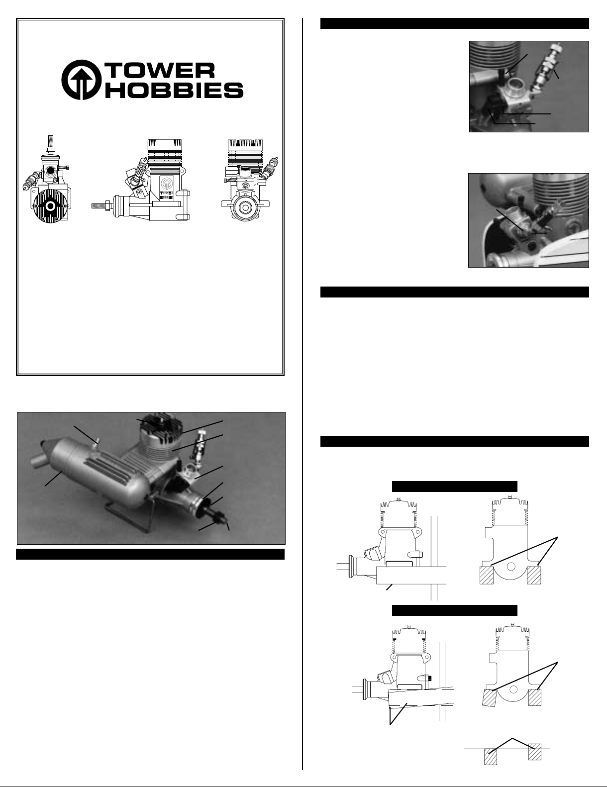
Parts of the Carburetor:
INSTRUCTIONS FOR
®
®
.40 ENGINE
Please read and follow this instruction manual before operating your engine.
Thank you for purchasing this high quality Tower .40 engine. Your engine was
produced to exacting tolerances with state-of-the-art computerized machine
equipment using the finest materials and should provide consistent, reliable
service for many years. The new safety needle valve design feature of this
engine is a step forward in engine technology, offering safer operation than
conventional needle valve locations. The ABC construction and schnuerle porting
will provide you with performance to meet your sport flying needs, along with
easy starting and reliability. Like all model airplane engines, care must be taken
in operation as severe injury can result from improper or careless use. Please
read and understand the safety precautions and warnings in this manual before
operating this engine.
Pressure Fitting
Glow Plug
Important:
© Copyright, 1998
Cylinder Head
Crankcase
Needle Valve: The needle valve controls the
fuel/air mixture entering the carburetor.
Air Bleed Screw: The air bleed screw controls
the amount of fuel/air mixture entering the
carburetor while the engine is idling.
Idle Stop Screw: The idle stop screw controls
how far the throttle closes. We suggest that it
be set to allow the throttle to close completely
to stop the engine using the throttle trim on the transmitter.
Throttle Arm: The throttle arm is connected to the carburetor barrel and is operated by
the throttle servo. By moving the throttle arm,
the barrel can be opened and closed. This
adjusts the speed of the engine.
By loosening the nut next to the carburetor
body, the safety needle valve can be rotated.
By loosening the nut below the fuel inlet, the
inlet can be rotated. An optional straight
needle valve adapter (TOWG5260) is available
if the engine will be enclosed in a cowl.
How the Tower .40 Engine Operates:
The aluminum piston and chrome-plated brass cylinder are designed to have the proper
fit at normal operating temperature. As the engine warms up, each part expands,
producing the proper fit. If the fuel mixture entering the engine is wrong, the parts do not
expand properly. The engine will not run correctly and in some cases can be damaged.
The reason the fuel mixture is so important is that the fuel is a blend of oil (synthetic oil
and/or castor oil), nitromethane and alcohol; plus anti-wear and anti-foaming agents and
corrosion inhibitors. The Tower .40 engine will run best on fuel with a 5% to 15%
nitromethane content and a mixture containing castor oil or a castor-synthetic blend. The
nitromethane helps the alcohol burn better. The oil lubricates and cools the engine. So, if
the fuel mixture is not correct, the engine can overheat or will not get hot enough for the
cylinder to expand properly and provide maximum power.
Installation:
Loosen this
nut to rotate
the needle
valve.
Idle Stop
Screw
Needle
Valve
Air Bleed
Screw
Throttle Arm
Loosen
this nut to
rotate the
fuel inlet.
Carburetor
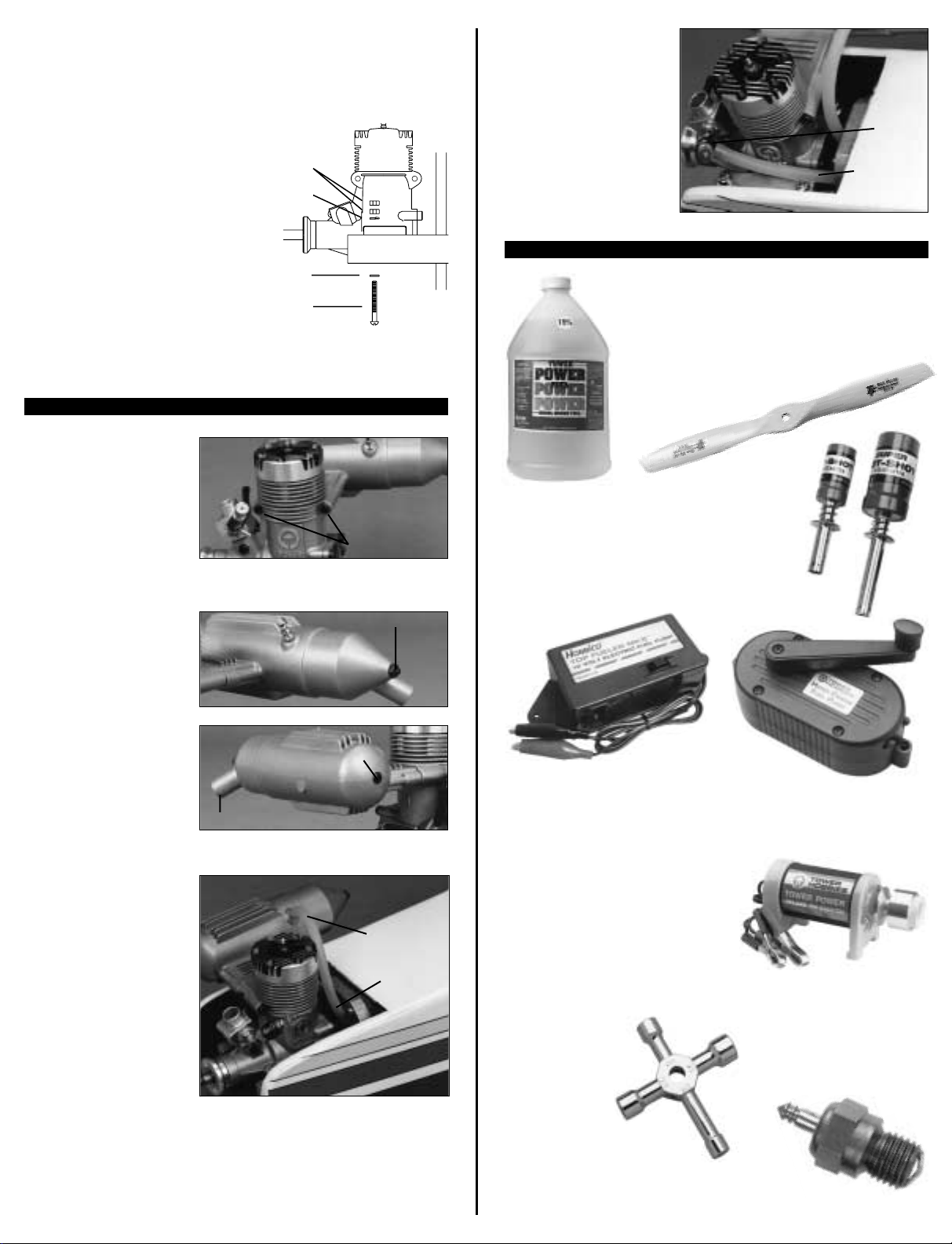
Muffler
Propeller Nut
Parts of the Engine:
Crankshaft: The crankshaft transforms the reciprocating motion of the piston into
rotational motion. The propeller is mounted on the portion of the crankshaft protruding
from the crankcase.
Propeller Nut: The propeller nut secures the propeller to the crankshaft.
Propeller Washer: The propeller washer provides a larger, stronger surface area to
apply pressure to the propeller.
Drive Washer: The drive washer is keyed to the crankshaft and is knurled on one face
to provide a good contact surface for the propeller.
Carburetor: The carburetor meters the amount of fuel and air that enters the engine.
Crankcase: The crankcase houses the internal parts.
Cylinder Head: The cylinder head is mounted on top of the crankcase. It provides a
seal at the top of the cylinder. The fins on the cylinder head provide a cooling surface.
The cylinder head also holds the glow plug.
Glow Plug: The glow plug provides the heat needed to ignite the fuel in the cylinder.
Muffler: The muffler quiets the exhaust exiting the cylinder.
Pressure Fitting: A tube is connected from the pressure fitting to the fuel tank. When
the engine is running, pressure from the muffler is used to pressurize the fuel tank.
Drive Washer
Propeller
Washer
Crankshaft
The beams the engine is to be mounted on must be rigid, parallel with each other and
the top surfaces in the same plane.
CORRECT
Top surfaces
of beams are
in the same
plane
Beams are parallel
INCORRECT
Top surfaces
of beams are
not parallel
Beams are not parallel
Top surfaces are not in
the same plane
Page 2
Set the engine on the beams at the correct angle to the center line of the fuselage,
according to the instructions provided by the airplane manufacturer. Mark on the beam the
locations of the four mounting holes. If mounting the engine on wooden beams, drill four
7/64” holes through the beams perpendicular to the top surface of the beams. Secure the
engine to the beams with 4-40 screws, flat washers, lock washers and 4-40 nuts.
If mounting the engine on a metal or fiberglass
engine mount, follow the manufacturer’s
mounting instructions. If they did not provide
instructions, drill and tap the engine mount to
accept 4-40 screws and lock washers installed
through the engine mounting flanges and into
the engine mount.
Note: Some airplane kits require a slight amount
of right thrust. This is done by angling the
engine to the right to counteract the torque
factor of the propeller while making thrust.
Follow the kit manufacturer’s instructions to
incorporate the correct amount of right thrust
if required.
Muffler Installation:
Install the muffler on the engine
after the engine has been installed
in the airplane. Insert the two
muffler screws through the
crankcase and thread them into
the muffler. Tighten the muffler
screws, being careful not to strip
the threads in the muffler.
To adjust the exhaust outlet,
loosen the lock nut at the rear of
the muffler, then loosen the screw
at the front of the muffler. Rotate
the exhaust outlet away from the
airplane. Re-tighten the screw at
the front of the muffler just tight
enough to prevent the exhaust
outlet from rotating. Then tighten
the lock nut at the rear of the
muffler. If the screw is overtightened the screw will break as
the muffler heats up and expands.
Pressure Line:
For the engine to operate properly
at any angle, the carburetor
requires constant fuel pressure.
When the engine is running,
pressure is created in the muffler
by the exhaust. Some of this
pressure is used to pressurize the
fuel tank. This pressure is provided
by a tube from the pressure fitting
on the muffler to the vent tube in
the fuel tank. Although not
absolutely necessary, pressurizing
the fuel tank with muffler pressure
will provide more consistent
running, and will help to maintain
more consistent fuel flow during
maneuvers. We recommend the
use of muffler pressure.
Fuel Line:
Connect a medium size silicone
fuel line from the fuel inlet on the
carburetor to the fuel pick-up tube
that is connected to the clunk in
the fuel tank. We suggest that a
fuel filter be installed in the fuel
line between the carburetor and
the fuel tank. The filter will prevent
any contaminants in the fuel from
clogging the carburetor.
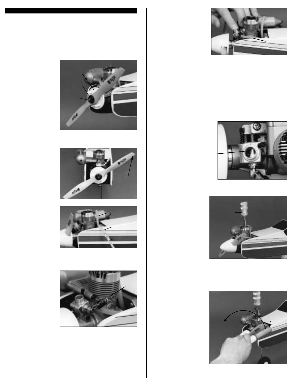
Equipment Required to Operate the Tower 40 Engine
Muffler Screws
Loosen this nut
Rotate the exhaust outlet
Loosen this screw
From fuel
pick-up tube
in fuel tank
Fuel
Inlet
Glow Plug Wrench:
The glow plug will
eventually fail to
retain heat or it will
need to be removed
to clear a flooded
engine. We
recommend a Hobbico 4-Way
Wrench (HCAP2550) that can be
used to remove the glow plug and the
propeller nut.
Propeller: For "break-in" and most
trainer and sport airplanes, we
suggest a Top Flite 10x6 Propeller
(TOPQ5085). A 10x5 (TOPQ5080) or
an 11x4 Propeller (TOPQ5095)
may also be used.
Chicken Stick or Electric Starter: Again, if a
field box is used, we recommend a Tower
Hobbies Electric Starter (TOWP0500). If you do
not have a field box with a 12 volt battery, a
chicken stick can be used to flip the propeller
to start the engine.
Caution: never use your finger to flip the
propeller. If the engine should backfire, the
propeller could injure your finger.
Glow Plug Battery: For ease of operation and safety we
recommend a Hobbico Glow Plug Clip (HCAP2505) with the
self contained battery. If using a Tower Hobbies Glow Plug
Clip (TOWP1200) connected to a power panel on a field box,
make sure the wire lead is behind the propeller when
starting the engine.
Nuts
Lock
Washer
Washer
4-40
Screw
Rigid Beam
Attach to
pressure fitting
on muffler
From vent
tube in
fuel tank
Glow Plugs: For best
performance and sure-fire
starts, we recommend using
Tower Hobbies R/C Long Glow
Plugs (TOWG1001).
Fuel Pump: If you will be using a field box, we recommend a
Hobbico Electric Fuel Pump (HCAP3100) that can be mounted on the field box. If you
will not be using a field box, we recommend a Tower Hobbies hand Crank Fuel Pump
(TOWP1210).
High Quality Fuel: We
recommend two-stroke fuel
with 5% to 15%
nitromethane and a
mixture containing
castor oil or a castorsynthetic blend.
Tower’s own Tower
Power brand fuel is
recommended.
Page 3
Starting the Engine
Before installing, check your glow plug by briefly attaching the glow plug battery to the
plug. The plug must glow brightly.
1. To install the glow plug in the engine first slide the compression washer on the glow
plug. Carefully install the glow plug in the top of the cylinder head with your fingers.
Tighten the glow plug finger tight then use a glow plug wrench to tighten the glow plug
securely. Do not overtighten the glow plug or the threads in the cylinder head may strip.
2. First balance your propeller
using a prop balancer such as the
Top Flite Precision Magnetic
Balancer (TOPQ5700). To install
the propeller on the engine,
remove the propeller nut and
propeller washer. If installing a
spinner, install the spinner back
plate first, following the
manufacturer’s instructions. Next,
install the propeller with the
rounded surface of the propeller
blade facing forward. Install the
flat side of the propeller washer
against the propeller. Thread the
propeller nut against the propeller washer, but do not tighten it. Rotate the crankshaft
of the engine counterclockwise to the compression stroke (the crankshaft will become
difficult to turn).
Spinner
Back Plate
Propeller
Washer
Propeller
Nut
5. Turn the transmitter and receiver
on. Set the throttle at high. Do not
attach the glow plug clip at this
time. Look at the fuel line going to
the carburetor, you should be able
to see if there is fuel in the line. If
the line is empty or has bubbles,
place your finger over the opening
in the carburetor while rotating the
propeller counterclockwise until
fuel reaches the carburetor. Rotate the propeller one to two more times. Remove your
finger from the carburetor and flip the propeller counterclockwise three or four more
times to distribute the fuel in the engine.
The engine is now ready to be started. If the above five steps sound like a lot of work in
preparation for starting an engine, it’s not. In actual practice, you will only need to
perform steps 3 and 5 after the engine has been started for the first time.
6. Have an assistant hold the airplane securely from behind the wing to prevent the
airplane from moving forward. You will see some modelers starting their engine with
one hand while holding their airplane with the other. This is an unsafe practice that
greatly increases the chances of having an accident.
7. Set the throttle so that the carburetor
is about 1/8 to 1/4 open.
Is there
fuel in the
fuel line?
Continue rotating the propeller
until it’s at the 2:00 o’clock
position, then tighten the propeller
nut securely against the propeller
washer. Some people use a 4way wrench for this purpose, but
it is difficult to get the nut tight
enough with that type of wrench.
Many modelers use a 6-inch
adjustable wrench for tightening
prop nuts.
3. Fill the fuel tank by removing the
fuel line from the fuel inlet, on the
carburetor, and connecting it to the
fuel tubing from the fuel pump.
Remove the pressure line from the
pressure fitting on the muffler and
aim it at the ground where you
want the overflow fuel to spray.
Environmentally conscious modelers direct this fuel into an “overflow bottle.” Start filling
the fuel tank. When the tank is full, fuel will overflow out the pressure line. Disconnect
the fuel line from the fuel pump and reconnect it to the carburetor. Reconnect the
pressure line to the muffler.
4.
The first time you run your new
engine, gently screw in the high
speed needle, turning it clockwise
until you feel resistance. This
should be done with a light touch,
to avoid screwing the needle in too
far and damaging it. Now unscrew
the needle exactly 3 turns. Every
engine is slightly different, but the
engine should be able to start and
run rich* at this setting.
will make this adjustment only once, when you prepare to start the engine for
the very first time.
*“Rich” means that there is a lot of fuel in the fuel/air mixture. An engine that is
“running rich” is probably running rough and spitting excess fuel out of the carburetor,
and the cylinder head is only warm.
*“Lean” means that there is not enough fuel in the fuel/air mixture. An engine that is
“running lean” is probably running fast and smooth, but the cylinder head is very hot.
Running the engine “lean” can damage your engine and void your warranty.
Note: You
2:00
Position
Pressure Line
from Muffler
Fuel Line from
Carburetor
Fuel Tubing
from Fuel
Pump
Needle
Valve
Carburetor is
between 1/8
and 1/4 open.
8. Securely attach the glow plug
clip to the glow plug. If using a
glow plug clip connected to the
power panel of a field box, make
sure the wire cannot become
entangled in the prop.
9. If using a chicken stick to start
the engine, flip the propeller
counterclockwise using quick
flips. If the engine fails to start
after 10 flips, it may not have
enough fuel in the engine.
Remove the glow plug clip and
repeat the priming process. If the
propeller becomes difficult to
rotate, the engine is flooded with
fuel. Remove the glow plug and
turn the airplane upside down
(pointing away from you), and flip
the propeller backwards a few
times, allowing the excess fuel to
drain out. Reinstall the glow plug,
attach the glow plug clip and try starting the engine again. Do not under any
circumstances attempt to start engine using only your finger.
Attach Glow
Plug Clip
Flip with
Chicken
Stick
Page 4

If using an electric starter to start the engine, make sure the starter is turning
counterclockwise. If your engine has a spinner on it, place the large opening of the
rubber adapter on your starter against the spinner. Turn the starter on and hold it
against the spinner until the engine starts. Because the engine is new, it may be tight.
You may need to turn the starter on first and bump the spinner with the rubber adapter
to get it started the first few times. If only a propeller nut is on the front of the propeller,
turn the rubber adapter on the starter around and center the small hole of the rubber
adapter over the nut. Turn the starter on and hold it against the propeller until the
engine starts. If the starter has difficulties turning the engine, the engine may be
flooded with fuel. Clear the engine of fuel as described above. Do not continue to try to
start a flooded engine. The connecting rod in the engine could be damaged.
10. After the engine starts allow it to warm up for 15-30 seconds before removing the
glow plug clip. Do not reach around the spinning propeller to remove it, as this is how
many accidents happen. Instead, reposition yourself behind the propeller before
removing the glow plug clip or adjusting the needle valve.
Engine “Break-in”
Have an assistant hold the airplane securely. Start engine and advance to full throttle.
Slowly, by turning “clockwise,” lean the needle valve. As you do this, you will hear the
engine pick up speed, with the exhaust sound becoming higher in pitch. At the same
time, you will also hear that the engine will start running smoother. At some point, the
sound of the exhaust will start trying to change from a low pitch to a higher pitch
sound. It will alternate back and forth as you adjust the needle. Continue to slowly lean
the needle valve.
Eventually, the engine will be running mainly at the higher-pitch sound with an
occasional misfire or momentary change to the lower-pitch sound. “Richen” the needle
5-6 clicks from this point, and allow the engine to run at this setting for at least five
minutes.
If, at some time during the break-in process, the engine runs the tank out of fuel, don’t
change the needle valve setting. Just refill the fuel tank, set the throttle at 1/4 open,
connect the glow plug clip, and start the engine. Since it’s been running, it should start
easily. If it doesn’t start right away, remove the glow plug clip, and prime the engine as
described above. Once you’ve restarted the engine, advance the throttle to full and
continue the process.
After five minutes, give the fuel
line a quick pinch. You should
hear the engine increase speed
then return to normal. If, when
you pinch the fuel line, the
engine does not change speed,
or if it slows down, immediately
richen the needle valve at least
1/4 turn. Try pinching the fuel
line again.The engine MUST
increase speed when the fuel
line is pinched.
If, when you pinch the fuel line,
you do get an increase in engine
speed, repeat the pinch five
times at 30-second intervals, but
do not adjust the needle valve
between pinches.
Now lean the needle valve about 1/8 turn (clockwise). The engine should increase
speed slightly. Allow the engine to run at this setting for a minute or two and then
repeat the pinching process like before (five pinches at 30-second intervals). Did the
engine jump in speed? If so, then lean the needle another 1/8 turn (clockwise).
Continue this process until a quick pinch will result in no change in engine speed.
If, at any point, the engine starts to slow down while you are leaning the needle valve,
or when you pinch the fuel line, immediately stop and turn the needle valve back at
least 1/4 turn (counterclockwise). This means that you have turned the needle valve
too far. If this happens when you first start adjusting the needle valve, run the engine
longer at the first setting, it hasn’t run long enough to accept the new setting.
Eventually, you will get to the point where a quick pinch will not cause the engine to
speed up. You will either hear no change, or the engine will slow down a bit. Richen
the needle valve so that you can hear the engine speed up when you give the fuel line
a pinch. Allow the engine to run at this setting for a full tank of fuel.
While the engine is running at this setting, pinch the fuel line occasionally to make sure
you get a speed increase. As the fuel level in the tank lowers, most engines will tend to
lean a bit, so make sure the needle valve setting allows for this. If the engine will run at
this setting for an entire tank of fuel, it’s time to set the idle speed and mixture.
Adjusting the Idle
Slowly close the throttle. The engine will begin to slow down. You will also hear it start
to misfire and run a bit rough. This is normal. The carburetor opening should be about
1/16” open when the engine is idling.
If the engine will not idle smoothly, or tries to stop, the air-bleed screw will need to be
adjusted. With the engine running, close the throttle to a point just short of where the
engine stops. Pinch the fuel line. If the engine speeds up a bit, the mixture is rich.
Stop the engine and turn the air-bleed screw counterclockwise 1/4 turn. Restart the
engine and repeat the process until no change occurs. Note that the airbleed screw is
adjusted exactly in reverse of the needle valve (for the airbleed screw, “in” (turning
clockwise) is rich, and “out” (turning counterclockwise) is lean).
If the engine slows down when you pinch the fuel line, the mixture is lean. Richen the
airbleed screw 1/4 turn clockwise. Repeat the process until you get no change in
engine speed when you pinch the fuel line.
Since the engine is running slowly, a very quick pinch may not have much effect. You
may have to pinch the fuel line for a few seconds. Don’t pinch off the fuel line long
enough to stop the engine.
Another way to check your idle setting is to throttle down the engine and then let it idle.
If it gradually slows down and then quits, lean the airbleed screw. If it speeds up just
before it quits, richen the airbleed screw.
Once you have the air bleed screw adjusted and the engine idles smoothly, move the
throttle from idle to full speed. There may be a slight hesitation as the throttle is
advanced, but this is normal. The engine should not be sluggish going from idle to full
speed. There should also be a smooth transition when the throttle is reduced from full
speed to idle. The engine should be idling the same as in the beginning of this step.
Your engine is now ready to fly.
Stopping and Restarting the Engine:
To stop the engine before it runs out of fuel, we suggest that the radio be set up so
that when the throttle and throttle trim are moved to the low-speed position, the
carburetor can be completely closed. If your throttle was not set up this way, pinch the
fuel line from the fuel tank to the carburetor to stop the engine.
Restarting the Engine:
If the engine is still warm, try to start the engine without priming it first. If the engine
has cooled down it may need to be primed.
If the engine does not start after priming, the engine may be flooded. Clear the excess
fuel from the engine as described before. Attach the glow plug clip to the glow plug
and check that it glows bright orange. If it does, re-install it in the engine. If it does not,
replace the glow plug with a new one. Try to restart the engine without priming it.
Turn with
electric starter
Rotate the
needle valve
counter
clockwise to
"richen" the
engine
Rotate the
needle valve
clockwise to
"lean" the
engine
Do not adjust screws while engine is running
Page 5

Care and Maintenance:
• We suggest that a fuel filter be installed between the carburetor and the
fuel tank to prevent dirt from entering the carburetor.
• At the end of a day of flying, remove all the fuel from the fuel tank. Start
the engine and allow it to run at idle until it stops. This will remove any
fuel left inside of the crankcase.
• Put a few drops of a quality “after-run oil” in the carburetor. Flip the
propeller a few times to distribute the oil throughout the engine. This will
prevent rust and corrosion from damaging the engine.
• Wipe off the outside of the engine with denatured alcohol to remove any
fuel residue and dirt. If the residue is left on the engine, the heat from
the engine will bake it on the next time it is run. Baked on residue
reduces the cooling of the engine.
• Do not disassemble the engine unless you are a qualified to do so.
• Avoid running the engine in dusty conditions. If the area you fly in is
dusty, such as a dirt runway, we suggest installing an air filter made for
airplane engines.
• After flying, check all engine mounting bolts, muffler screws, propeller
nut and spinner to make sure they have not loosened up.
Safety Precautions and Warnings
1. Keep all spectators at least 20 feet away when operating engine.
2. Keep yourself out of the path of the prop. Do not lean over the propeller
when starting or adjusting the engine.
3. We recommend wood propellers only. All plastic or fiberglass props
require special handling. Follow instructions of the propeller manufacturers.
4. Always balance the propeller before installing it on the engine. Never use
a propeller that is damaged, no matter how slight.
5. Make sure the edges of the spinner do not touch the propeller blades.
The sharp edges may cut into the propeller blades and cause them to
break.
6. Be sure your glow plug cord will not interfere with the propeller when
running.
7. Never use your fingers to start the engine. Always use a chicken stick or
electric starter.
8. Make all engine adjustments from behind the propeller. Always stop the
engine before adjusting idle stop screw or air bleed screw.
9. Do not operate the engine in an area with loose gravel or sand.
10. Wear safety glasses when starting and running the engine.
11. Keep all loose clothing such as neck ties and shirt sleeves away from
the propeller. Remove any objects from your shirt pockets to prevent them
from falling into the propeller.
12. Keep all engine fuel away from children, sparks and excessive heat.
Do not smoke while handling model fuel. Model fuel is highly flammable
and must be handled with caution.
13. Never operate the model engine in an enclosed area. The engine
produces deadly carbon monoxide and must be run in a well ventilated
area.
14. Model engines get very hot when running. Do not touch any part of the
engine until it cools.
Does it run
continuously?
It should
be ready
to go.
NO NO
YES
YES
YESYES
NO
YES
NO
NO
NO
YES
YES
YES
NO
YES
NO
NO
YES
The engine starts
Is fuel
getting to
the
engine?
Check for
clogging in
the
carburetor
or fuel line
and check
needle
valve
setting.
Is the
needle
valve
setting 2-
1/2 to 3
turns out
from
closed?
Try starting the
engine again.
Does the
engine quit
when the
glow plug
clip is
removed?
The
engine
may be
flooded.
Reset the
needle
valve.
Replace
the glow
plug.
Check that
the pressure
line is
connected to
the muffler.
The fuel may
be bad.
Does the
engine
turn over
easily?
Is fuel in
the fuel
line?
Is the
glow plug
red hot?
Remove
to check.
Check the
needle
valve
setting and
prime the
engine.
Is foreign
matter
clogging
the fuel
tank or
fuel line?
Is the
battery
for the
glow
plug clip
charged?
The engine does not start
The
engine
may be
flooded.
Check
needle
valve
setting.
Remove the
obstruction
from the fuel
tank or fuel
line.
Charge
or
replace
the
batteries
Replace the
glow plug.
Try starting the
engine again.
Trouble Shooting:
May need
to remove
glow plug
and turn
over
engine,
also clean
glow plug.
Page 6
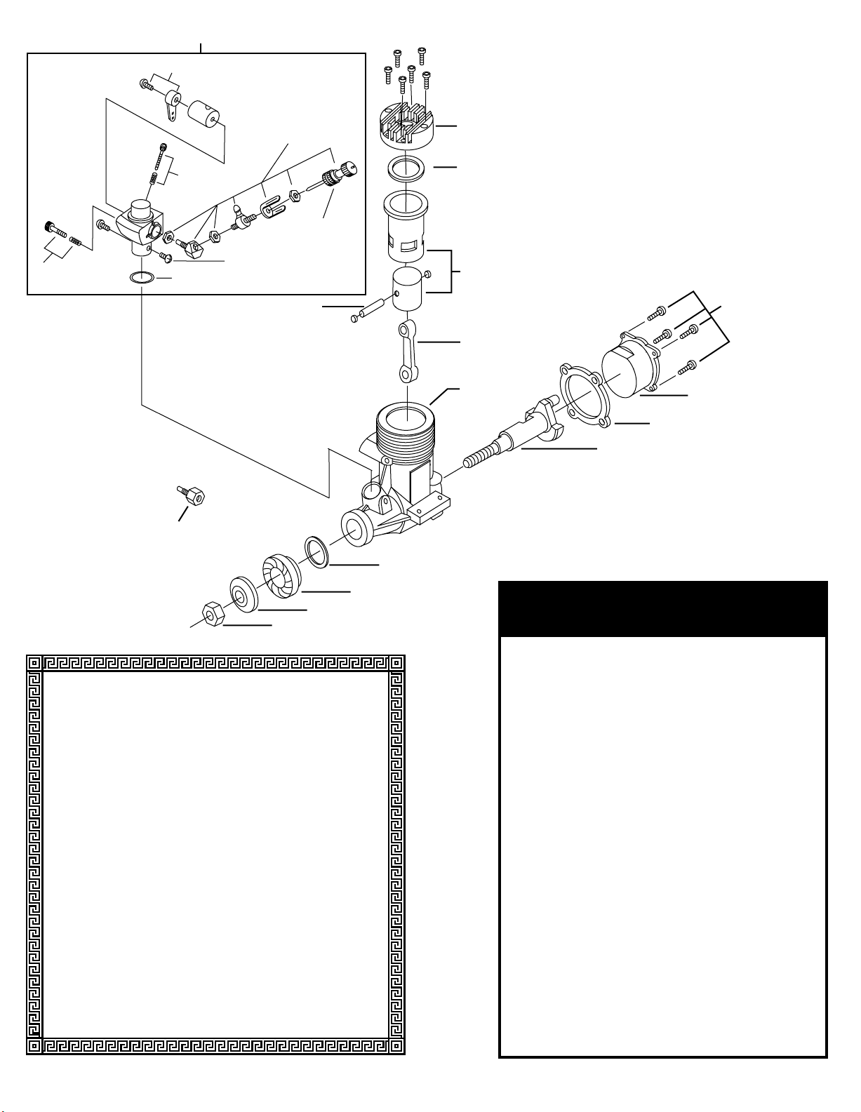
TOWG4100 (Carburetor Assembly)
Limited Warranty:
Your engine is warrantied to be free of defects in parts and workmanship
for a period of 2 years from the date of purchase when returned for service
accompanied by your proof of purchase. Crash damage and problems
caused by neglect, abuse or over-leaning will not be covered under
warranty. Damage caused by customer disassembly, tampering, use of
substandard fuel, use of incorrect accessories (glow plug, propeller, etc.),
or any use of the engine for which it is not specifically intended will
automatically void the warranty of the engine. Should your engine require
warranty or non-warranty service, please return it via an insured shipper to
our national servicing facility.
Hobby Services
P.O. Box 9021
1610 Interstate Dr.
Champaign, IL 61821
Ph. (217) 398-0007
9:00 A.M.to 5:00 P.M.Central time. Monday through Friday
Along with your engine and proof of purchase date, please enclose a
complete written explanation detailing the problems. State your name and
address clearly. For repairs not covered under warranty, you must specify
whether you wish the charges to be billed C.O.D. or if you wish to be
notified of the charges so you can send a check. VISA and MasterCard are
also accepted
Ordering Parts is Easy —
Just Call Tower Hobbies Toll Free at
1-800-637-6050
STOCK # DESCRIPTION
TOWG4100. . . . . . CARBURETOR ASSEMBLY
TOWG4220. . . . . . CARBURETOR SCREWS IDLE AND STOP
TOWG4290. . . . . . CONNECTING ROD
TOWG4330. . . . . . COVER PLATE
TOWG4370. . . . . . CRANKCASE
TOWG4410. . . . . . CRANKSHAFT
TOWG4450. . . . . . CYLINDER LINER AND PISTON
TOWG4490. . . . . . CYLINDER HEAD
TOWG4570. . . . . . DRIVE WASHER
TOWG4650. . . . . . GASKET SET (3)
TOWG4720. . . . . . MUFFLER ASSEMBLY
TOWG4760. . . . . . MUFFLER ASSEMBLY SCREW
TOWG4840. . . . . . MUFFLER MOUNTING SCREWS
TOWG4880. . . . . . NEEDLE VALVE
TOWG4990. . . . . . PRESSURE TAP
TOWG5030. . . . . . PROPELLER NUT
TOWG5070. . . . . . PROPELLER WASHER
TOWG5160. . . . . . SCREW SET (12)
TOWG5220. . . . . . SPRAYBAR ASSEMBLY-ANGLED
TOWG5260. . . . . . SPRAYBAR ADAPTER-STRAIGHT
TOWG5300. . . . . . THROTTLE ARM AND SCREW
TOWG5340. . . . . . THRUST WASHER
TOWG5400. . . . . . WRIST PIN WITH RETAINERS
TOWG5300
TOWG5160 (6 pcs.)
TOWG4220
(OPTIONAL STRAIGHT
SPRAY BAR ADAPTER)
TOWG4220
TOWG4650
TOWG5260
TOWG5220
TOWG4880
TOWG5160 (2 PCS)
TOWG5400
TOWG5340
TOWG4490
TOWG4650
TOWG4450
TOWG4290
TOWG4370
TOWG5160(4 pcs.)
TOWG4330
TOWG4650
TOWG4410
TOWG4570
TOWG5070
TOWG5030
 Loading...