

TOWA AX-100 Service Manual
Service Manual
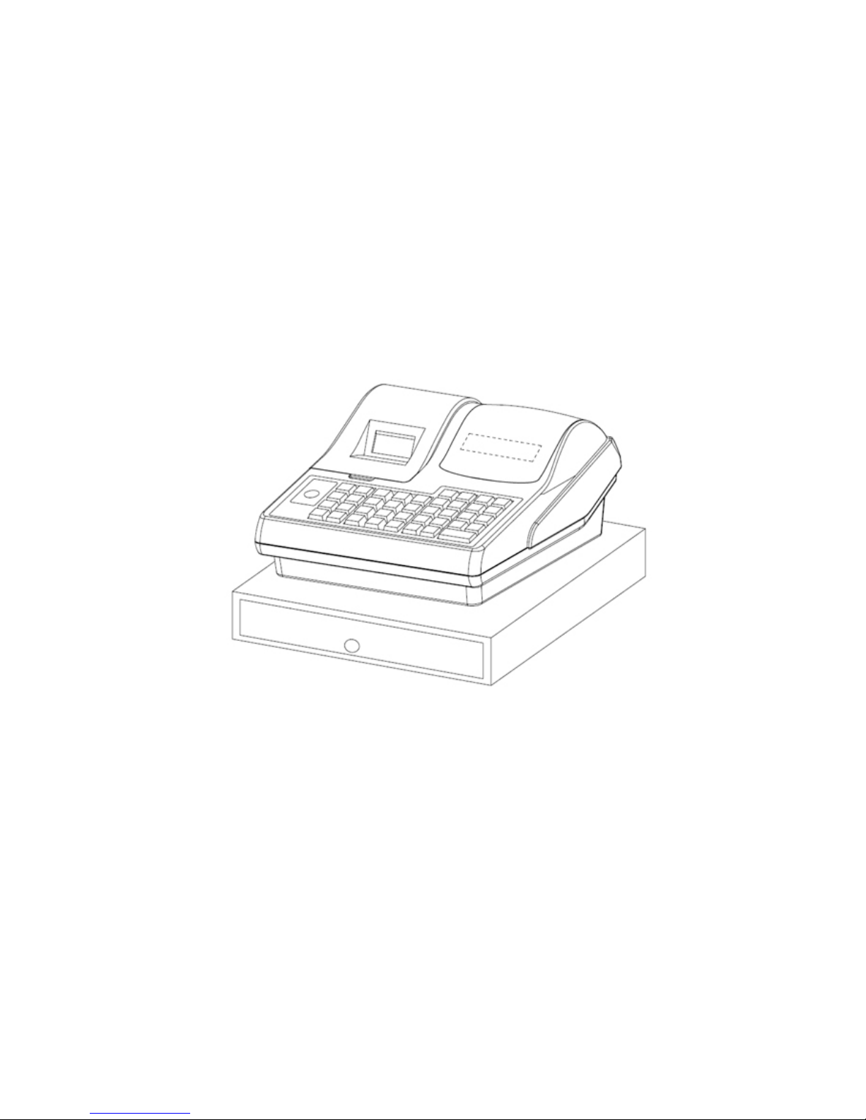
AX-100 (Black)
TOWA Business Precision Electronics (Zhong Shan) CO., LTD.
2007-07
Table of contents

1
Ⅰ.Product Specification ......................................................................................................................................... 2
1.General Specification ................................................................................................................................... 2
2.Function Specification ................................................................................................................................. 3
Ⅱ.Initialization ....................................................................................................................................................... 6
1.Control lock and its function ....................................................................................................................... 6
2.System clear ................................................................................................................................................. 6
3.System reset ................................................................................................................................................. 6
Ⅲ.Module connection diagram .............................................................................................................................. 7
Ⅳ.Circuit instruction .............................................................................................................................................. 7
1.Power supply circuit .................................................................................................................................... 7
2.Reset and power failure circuit .................................................................................................................... 9
3.Front display control and keyboard scan circuit ........................................................................................ 10
4.Rear display control circuit ........................................................................................................................ 12
5.Print circuit ................................................................................................................................................ 12
6.Communication circuit .............................................................................................................................. 13
7.CPU(IC1)Resource allocation .............................................................................................................. 14
8. RAM(IC3) .......................................................................................................................................... 16
Ⅴ.Classify by common malfunctions and dispose of method .............................................................................. 17
(1)Entire machine exceptionally ................................................................................................................. 17
(2)Data exceptionally ................................................................................................................................. 18
Ⅵ、PCB layout diagram(Top layer) .................................................................................................................. 19
Ⅶ、List of entire machine ...................................................................................................................................... 20

2
.Product Specification
1.General Specification
1、Front display8 digits, 8-segments LED(Including decimal point)
Your cash register has one 8-segments displays for the operator. It displays prices, subtotals,
change due, status codes and so on. This display can show up to eight digits.
2、Rear display: as same as the front display
3、Printer
SII CO.,LTD single-station thermal printer
Model : LTP 8235B
Specification: (Actual use value)
Drive voltage: 7V
Printing column: Symbol Max 24(12x24)
Printing speed: Max 10 lines/sec; Average 7 lines/sec
Paper roll size: 56.5-57.5 mm (2.22-2.26 inches)
Sensor : Lack of paper sensor, over hot sensor
4、Port A RS232 Port,adopt the RJ45 terminal (male port),RS232 Port can be connected to
communicate with the PC and the Bar code reader。
5、Power supply adopt single-route output transformer (input220V AC or 240V AC ±10%,
50Hz ,outputAC11V 2A)
6、Save datadry battery。
7、Keyboard
Type : Raised type only
Key number: 1 feed key
There are 38 free keys can be set, The CASH TEND key is a double size key,
each key has been preset a function with silk-screen name and attaches key cap
Control lock: 5 different modes :P,L,R,X,Z
8、Drawer Model N26 or NP33
9、Software supports language for printing and display English

3
2.Function Specification
1、Support the setting of date、time、machine number、receipt number、setting password、training
password、report number and so on
2、Department number16 (there are 8 direct departments number,by pressing the Department
Shift Key the department number can be achieve 16)
1)Name16 characters
2)Unit priceMax can be set up to 8 digits (include decimal) when in sale can be manually
input 7 digits (include decimal),
3)Flag Flag 1Assign the department to a group (0-9).
Flag 2Single / more item sale,+%、-% allow and negative department
Flag 3High amount lock out (HALO) (It’s only effective for the manually input
price)
Flag 4 Set up departments application tax rate info Tax1,Tax2,Tax3,Tax4
4)Other Support periodical report and daily report,when the department single transaction
amount exceeds 9 digits then a warning will give out,quantity 8 digits (4 integer,4
decimal)
3、PLU number200
1)Name16 bytes,
2)Unit priceMax can be set up to 8 digits (include decimal) when in sale can be input 7 digits
(include decimal)
3) Linked department1 byte (1-16)
4)Bar codeMax 13 digits
5)OtherSupport periodical report and daily report,when single transaction amount of
department exceeds 9 digits then a warning will give out,quantity 8 digits(4 integer,
4 decimal)
4、-%1,+%1, -1
5、Tax rate You can set up to 4 types of tax to be added to each item (VAT or ADD tax or tax
table)
6、Clerk10
1)Name12 bytes
2)Password4 digits
3)Clerk report content:net sale,cash amount,check amount,credit card amount,VOID amount

4
(include return and VOID),Non-add sale amount
7、LOGO Max 5 lines,each line max 24 bytes
8、MESSAGE Max 5 lines,each line max 24 bytes
9、Support main flag setting
10、Support keyboard setting
11、Support transaction name setting
12、Report function
Department group sales report(read report)
Full department sales report(read report)
Individual PLU sales report(read report)
Full PLU sales report(read and reset report)
Individual PLU link department sales report(read report)
Full PLU link department sales report(read report)
Individual clerk sales(read and reset report)
Full clerk sales(read and reset report)
Full report(read and reset report)
Drawer report(read and reset report)
Cash Declaration report(daily reset report)
Hourly Report
Training Report
13、Payment type
Supports Cash、Check、Credit card、Keep accounts、Foreign currency and Coupon payment
14、Other functions
Cancel operation
VOID operation
Return merchandise operation
Copy receipt
Time or date display
Report count function
X1:Daily read report
X2:Periodical read report
Z1:Daily reset report

5
Z2:Periodical reset report
Non-sales count
Half-height fonts print
Clerk login and logout function
Single-item sales function
Multiplication function (number*price mode)
Calculator function(addition、subtraction、multiplication、division)
Department and PLU repeat entry function
Barcode enter and look for PLU price (PLU number and Barcode number input)
RA、PO operation
Electronic journal function
6
.Initialization
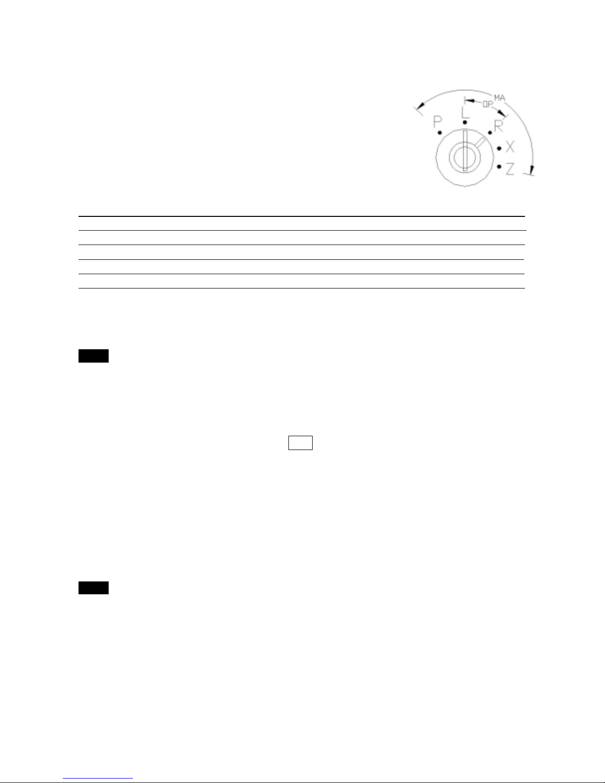
1.Control lock and its function
The control lock allows you to change the cash register mode. Your
cash register has 5 different modes. Conversion mode is the mode in which you
can insert manager key (MA) or operator key (OP) in the control lock and shift to
any position you need to carry out operation. The manager key can choose any
mode while the operator key can only choose “L” or “R” position.
The following table shows the modes the cash register is equipped with.
Mark Mode Name Functions
P Program mode Used to programming various cash register functions.
L Lock mode Used to turn off the cash register. This mode disables all operations.
R Register mode Used for normal checkout operations.
X Read mode Used to print sales information reports.
Z Reset mode Used to read and reset the sales informant
2.System clear
Before programming the cash register, you must clear the cash register’s memory
Notice
* Please do not perform the following steps during programming or normal operation. These steps
will clear all of the settings you have programmed and erase all sales information in the register.
1. Turn the manager’s key to the “L” position.
2. Remove the power cord from the outlet.
3. Turn the manager’s key to the “P” position.
4. Plug the power cord while pressing the CLR Key and hold the key down for at least two
seconds. When you release the key, “1” will appear in the display. At this point, the register
has been initialized.
Notice:These steps will clear all of the settings you have programmed and erase all sales
information in the register.
3.System reset
It is possible at some point in the programming or operation of the cash register due to a wrong
entry to cause the system to go into a loop. Use the following sequence to return to an operating
mode.
Notice
* Current transaction data will be lost, but, you will not lose any of the program or sales data. The
only data lost will be any sale not yet finalized by a method of payment.
1. Turn the manager’s key to the “L” position and remove the power cord from the outlet;
2. Turn the manager’s key to “P” position;
3. Plug the power cord into the outlet;
4. Turn the manager’s key to “R” position.
Note:Current transaction data will be lost, but, you will not lose any of the program or sales data.
7
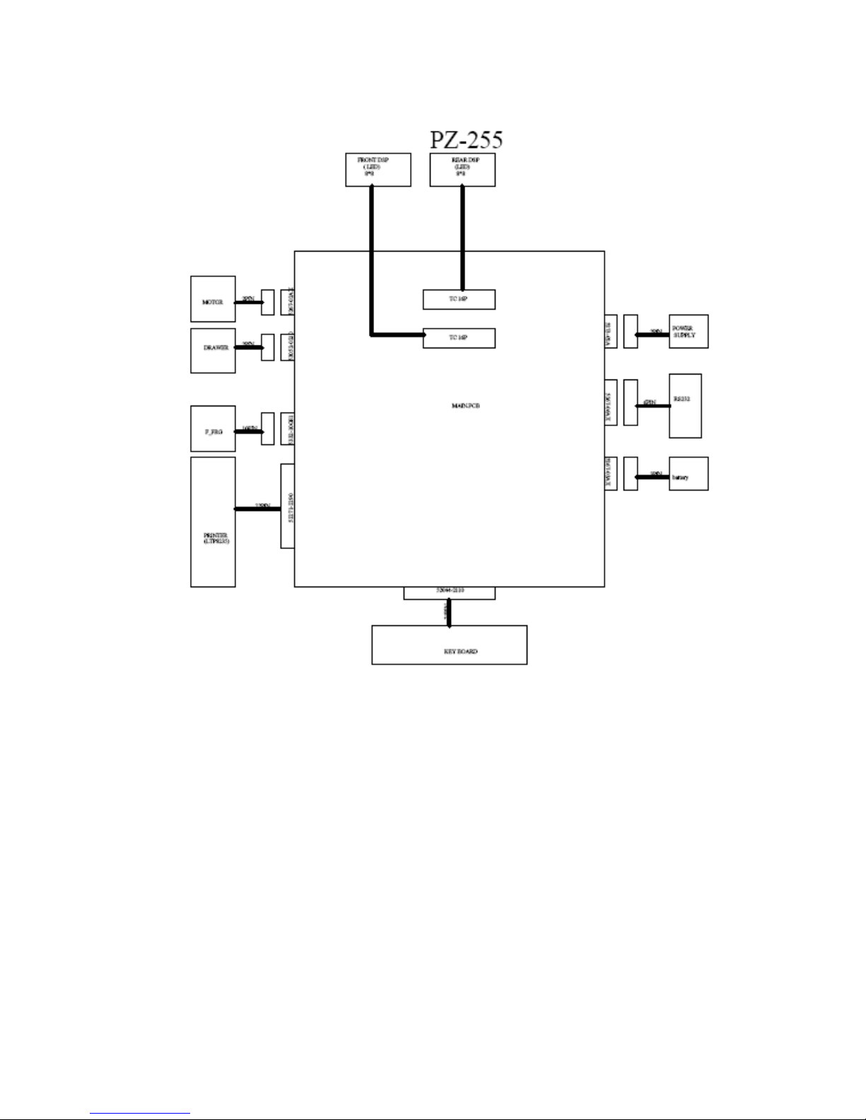
.Module connection diagram
.Circuit instruction
1.Power supply circuit
This cash register power is supplied by transformer,Input:220V AC or 240V AC
±10%/50Hz 0.15A,Output:AC11V/2A。
1-1、 +VCC:As shown in Fig.1,AC11V power supplied by transformer is input to mainboard
through PN4 terminal,After commuting, it will get the stable DC voltage +VCC (DC 15V).
1-2、+VCC:+13.1V~16.8V. Buzzer work voltage.
1-3、+5V:As shown in Fig.1, After the +VCC is converted by DC/DC chip IC2(7805),it will
 Loading...