

Tovis MTG-1971XT Service Manual
TOVIS P/N MTG-1971XT DATE 03/11/02
REV NO. 0
TOVIS
IGT P/N 69926200 / 69923301
PAGE 1/30
Color Monitor Service Manual
MODEL: MTG – 1971XT
TOVIS CO., LTD.

TOVIS P/N MTG-1971XT DATE 2002.03.11
REV NO. 0
TOVIS
Color Monitor Service Manual
PAGE 2/30
I N D E X
1. SAFETY PRECAUTIONS-------------------------------- 3
2. SPECIFICATIONS----------------------------------------- 4
3. TECHNICAL FEATURES ------------------------------- 5
4. TIMING CHART ------------------------------------------- 6
5. SET-UP ------------------------------------------------------ 8
6. CONTROLS AND ADJUSTMENTS ------------------ 9
7. ADJUSTMENT SPECIFICATIONS------------------- 18
8. DESCRIPTION OF CIRCUIT OPERATIONS------ 21
9. TROUBLE SHOOTING --------------------------------- 25
TOVIS CO., LTD.
TOVIS P/N MTG-1971XT DATE 2002.03.11
REV NO. 0
TOVIS
Color Monitor Service Manual
PAGE 3/30
1. SAFETY PRECAUTIONS
WARNING: Service should not be attempted by anyone unfamiliar with the
necessary safety precautions for this unit.
1-1.1. Some parts in this unit, such as the picture tube, have special safety
related characteristics for X-RAY RADIATION protection. For continued safety,
the parts replacement should be under taken referring to the below article
(1-2~1-5).
1-2. Many electrical mechanical parts in this unit have special safety-related
characteristics for protection against shock hazard and other potential harms..
These characteristics are often passed unnoticed by a visual inspection and
the protection afforded by them cannot necessarily be obtained by using
replacement components rated for higher voltage, wattage, etc. Replacement
parts, which have these special characteristics, are identified in the manual and
supplements by shading on the schematic diagram and the parts list. Before
replacing of these components read the parts list in this manual carefully.
1-3. When replacing chassis in the cabinet, always be certain that all the
protective devices are installed properly, such as insulating covers, strain relief,
etc.
1-4. Before replacing the back cover of the set, thoroughly inspect inside the
cabinet to see that no stray parts or tools have been left inside.
1-5 Before returning the set to the customer always perform an ac current leakage
check on the exposed metallic parts of the cabinet, such as terminal, screw
heads, metal overlays, control shafts, etc. To be sure the set is safe to operate
without danger of electrical shock, plug the AC line cord directly into an 115V
AC outlet (do not use a line isolation transformer during this check). Use an AC
volt- meter having 5000 ohms per volt or more sensitivity in the following
manner. Cannot use a 1500 ohm, 10watt resistor, paralleled by a 0.15 (uF)
capacitor. Reverse the AC plug the AC outlet and repeat AC voltage
measurements for each exposed metallic part. Voltage measured must not
exceed 0.3V RMS. This corresponds to 0.2mA AC any value exceeding this
limit constitutes a potential shock hazard and must be corrected immediately.
TOVIS CO., LTD.

TOVIS P/N MTG-1971XT DATE 2002.03.11
REV NO. 0
TOVIS
Color Monitor Service Manual
PAGE 4/30
2. SPECIFICATIONS
2-1. Picture Tube
∙Size : 19"
∙Dot Pitch : 0.25mm
2-2. Signal Input
∙Video Input : Analog, Positive Signal(0.7Vp-p)
∙Horizontal Sync : TTL Level, Positive or Negative pulse.
∙Scanning : 28Khz ∼ 70KHz
∙Vertical Input : TTL Level, Positive or Negative pulse.
∙Scanning : 40∼ 160Hz
2-3. Power Supply
∙Power Input : AC100∼ 240V, 60/50Hz
∙Fuse Rating : 250V, 50T 3.15A
∙Power Consumption
Normal: less than 130W
DPMS: less than 20W
2-4. External Control:
Refer to page 7.
2-5. Operating Temperature: 0℃∼ 55℃
2-6. Operating Humidity: 10%∼ 90%(Non-condensing)
2-7. Net weight: 23kg
TOVIS CO., LTD.

TOVIS P/N MTG-1971XT DATE 2002.03.11
REV NO. 0
TOVIS
Color Monitor Service Manual
PAGE 5/30
3. TECHNICAL FEATURES.
3-1. U-com (MCU) control with OSD.
U-com recognizes the computer signal and signal output from control board
connected with the wire. So the circuit is simplified.
3-2. Universal AC input voltage.
Power supply operates on AC100∼ 240volt 60/50Hz for use all over the
world.
3-3. Protection Circuit for over-current.
When over-current occurs in the circuit, the protection circuit operate in order
to prevent the components from electrical shock or other risks.
3-4. Override function
It is designed for the normal display when the monitor is powered on without
connecting from the source (No signal message).
3-5. Control panel
If you are not satisfied with the factory mode size, position, color settings,
use this control panel to program those you prefer in each resolution mode.
Then, these adjusted settings are kept in memory even if you change
resolution mode or turn off the monitor.
3-6. I
2
C BUS control
It is designed by I
2
C BUS control for simplifying the circuit.
TOVIS CO., LTD.
TOVIS P/N MTG-1971XT DATE 2002.03.11
REV NO. 0
TOVIS
Color Monitor Service Manual
PAGE 6/30
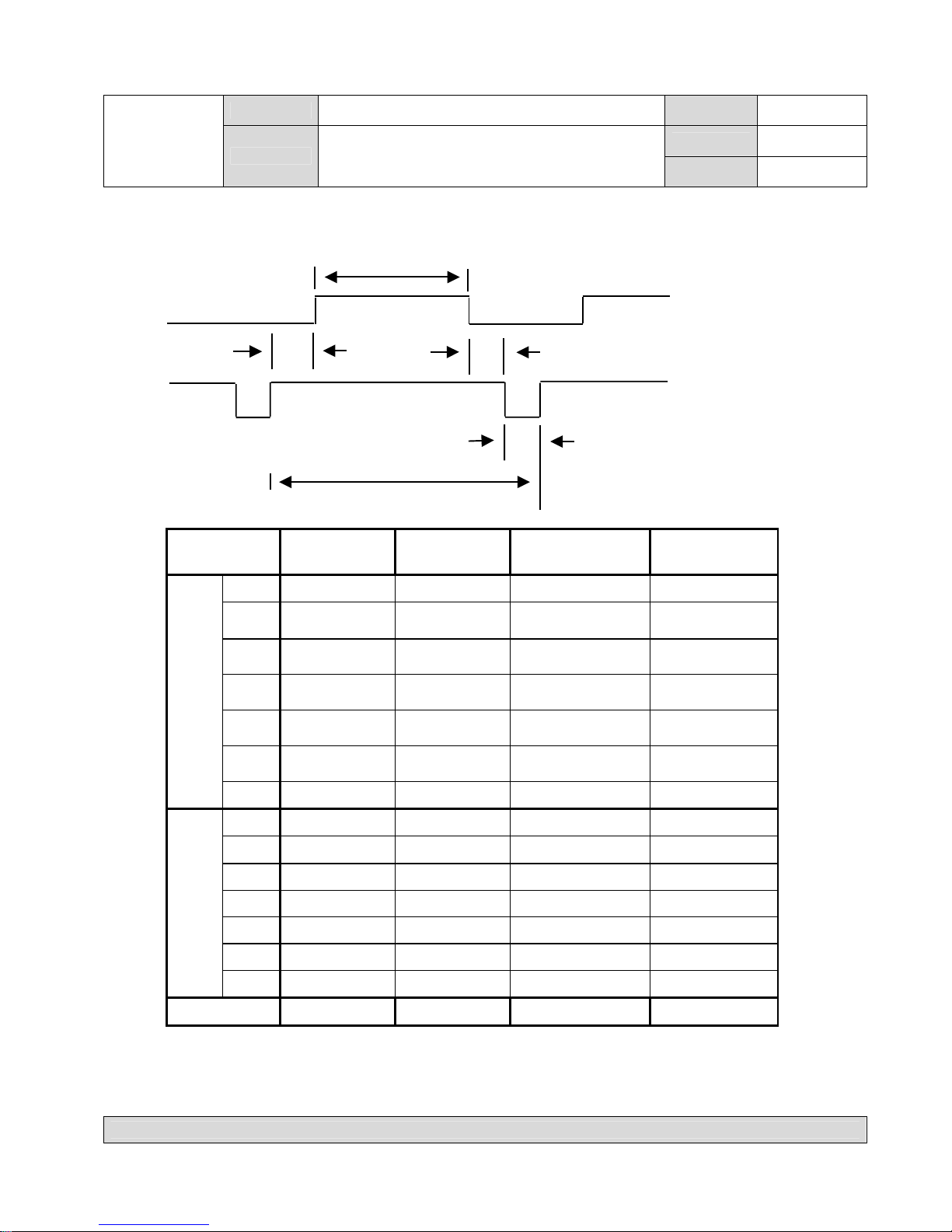
4. TIMING CHART
Factory Pre-Set Timing Modes.
D
VIDEO
C E
SYNC
B
A
DESCRIPTION
MODE 1
VGA 720*400
MODE 2
VGA 640*480
MODE 3
8514/A 1024*768
MODE 4
S-VGA 680*400
FH 31.469KHz 31.469KHz 35.552KHz 37.500KHz
A
31.778㎲ 31.778㎲ 28.251㎲ 26.667㎲
B
3.813㎲ 3.813㎲ 3.920㎲ 2.032㎲
C
1.907㎲ 1.589㎲ 1.247㎲ 3.810㎲
D
25.422㎲ 25.422㎲ 22.806㎲ 20.317㎲
E
0.636㎲ 0.318㎲ 0.170㎲ 0.508㎲
H
POL.
NEGATIVE NEGATIVE POSITIVE NEGATIVE
FH 70.087Hz 59.940Hz 86.960KHz 75.000Hz
A 14.268ms 16.683ms 11.500ms 13.333ms
B 0.064ms 0.064ms 0.113ms 0.080ms
C 1.112ms 0.794ms 0.563ms 0.427ms
D 12.711ms 15.253ms 10.810ms 12.800ms
E 0.381ms 0.064ms 0.014ms 0.027ms
V
POL.
POSITIVE NEGATIVE POSITIVE NEGATIVE
VIDEO ANALOG ANALOG ANALOG ANALOG
TOVIS CO., LTD.
TOVIS P/N MTG-1971XT DATE 2002.03.11
REV NO. 0
TOVIS
Color Monitor Service Manual
PAGE 7/30
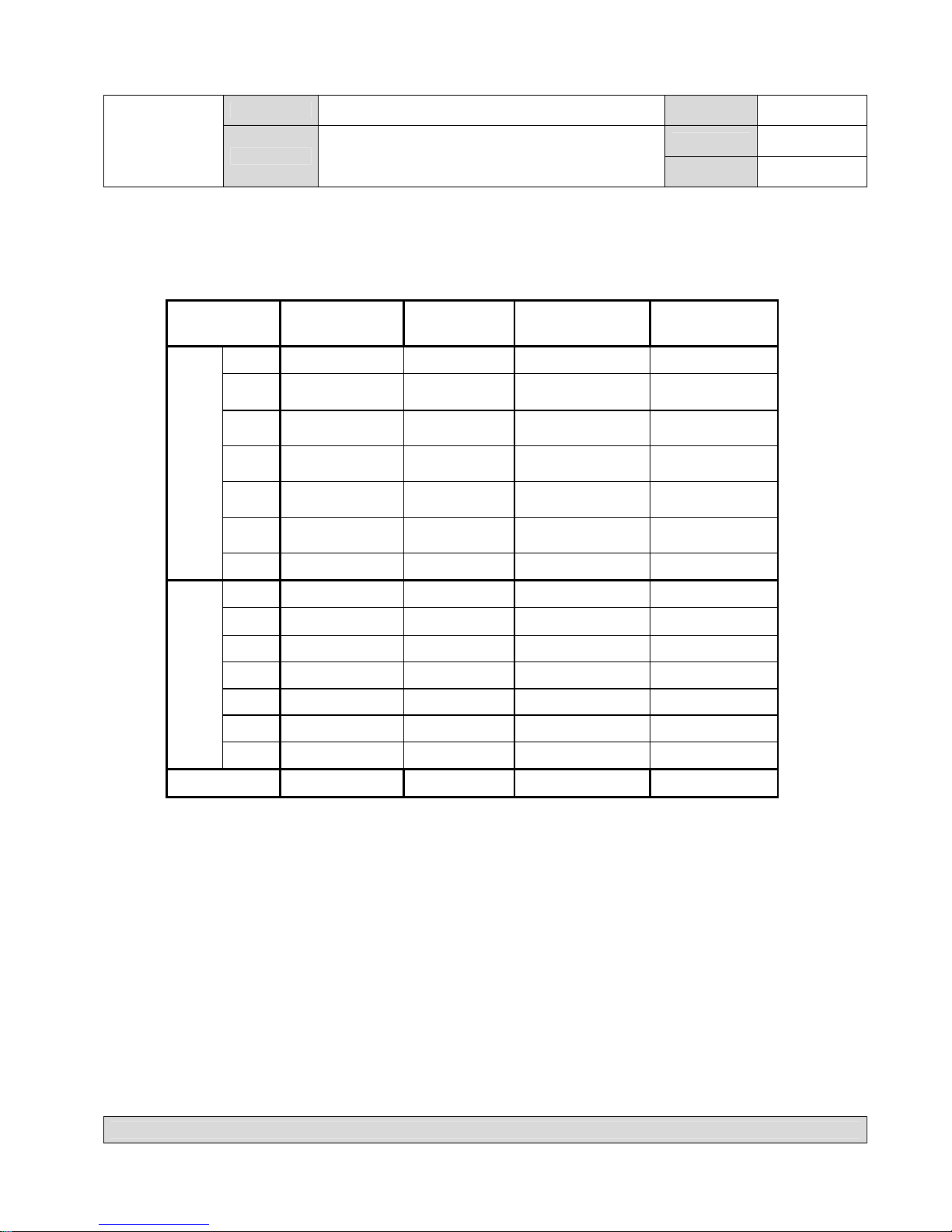
DESCRIPTION
MODE5 S-VGA
VESA 800*600
MODE6
VGA 800*600
MODE 7 VGA
VESA 800*600
MODE 8
VESA 1024*768
FH 37.879KHz 46.875KHz 48.077KHz 48.363KHz
A
26.400㎲ 21.333㎲ 20.800㎲ 20.677㎲
B
3.200㎲ 1.616㎲ 2.400㎲ 2.231㎲
C
2.200㎲ 3.232㎲ 1.280㎲ 1.615㎲
D
20.000㎲ 16.162㎲ 16.000㎲ 15.754㎲
E
1.000㎲ 0.323㎲ 1.119㎲ 0.998㎲
H
POL. POSITIVE POSITIVE POSITIVE NEGATIVE
FV 60.317Hz 75.000Hz 72.188Hz 60.004Hz
A 16.579ms 13.333ms 13.853ms 16.666ms
B 0.106ms 0.064ms 0.125ms 0.124ms
C 0.607ms 0.448ms 0.478ms 0.600ms
D 15.840ms 12.800ms 12.480ms 15.880ms
E 0.026ms 0.021ms 0.772ms 0.062ms
V
POL. POSITIVE POSITIVE POSITIVE NEGATIVE
VIDEO ANALOG ANALOG ANALOG ANALOG
TOVIS CO., LTD.

TOVIS P/N MTG-1971XT DATE 2002.03.11
REV NO. 0
TOVIS
Color Monitor Service Manual
PAGE 8/30
DESCRIPTION
MODE 9
VESA
800*600
MODE 10
VESA
1024*768
MODE 11
VESA
1024*768
MODE 12
VESA
1280*1024
MODE 13
VESA
1024*768
FH 53.674KHz 56.476KHz 60.023KHz 63.981KHz 68.677KHz
A
18.631㎲ 17.707㎲ 16.660㎲ 15.698㎲ 14.561㎲
B
1.138㎲ 1.813㎲ 1.219㎲ 1.037㎲ 1.016㎲
C
2.702㎲ 1.920㎲ 2.235㎲ 2.296㎲ 2.201㎲
D
14.222㎲ 13.653㎲ 13.003㎲ 11.852㎲ 10.836㎲
E
0.569㎲ 0.321㎲ 0.203㎲ 0.360㎲ 0.508㎲
H
POL. POSITIVE NEGATIVE POSITIVE POSITIVE POSITIVE
FV 85.062Hz 70.069Hz 75.029Hz 60.020Hz 84.997Hz
A 11.756ms 14.272ms 13.328ms 16.638ms 11.765ms
B 0.056ms 0.106ms 0.050ms 0.047ms 0.044ms
C 0.503ms 0.513ms 0.466ms 0.594ms 0.524ms
D 11.179ms 13.599ms 12.795ms 16.005ms 11.183ms
E 0.019ms 0.054ms 0.017ms 0.016ms 0.015ms
V
POL. POSITIVE NEGATIVE POSITIVE POSITIVE POSITIVE
VIDEO ANALOG ANALOG ANALOG ANALOG ANALOG
5. SET-UP
Setting up your monitor is easy. All you have to do is make a few simple
connections and adjustments. The procedure is as follows
.
5-1. Start Up
Your monitor starts up automatically when you insert the power plug to the power
source.
5-2. Signal cable Connection
Connect the 15pin-signal cable to the source and lock both screws to ensure that
the monitor is properly grounded.
TOVIS CO., LTD.
TOVIS P/N MTG-1971XT DATE 2002.03.11
REV NO. 0
TOVIS
Color Monitor Service Manual
PAGE 9/30
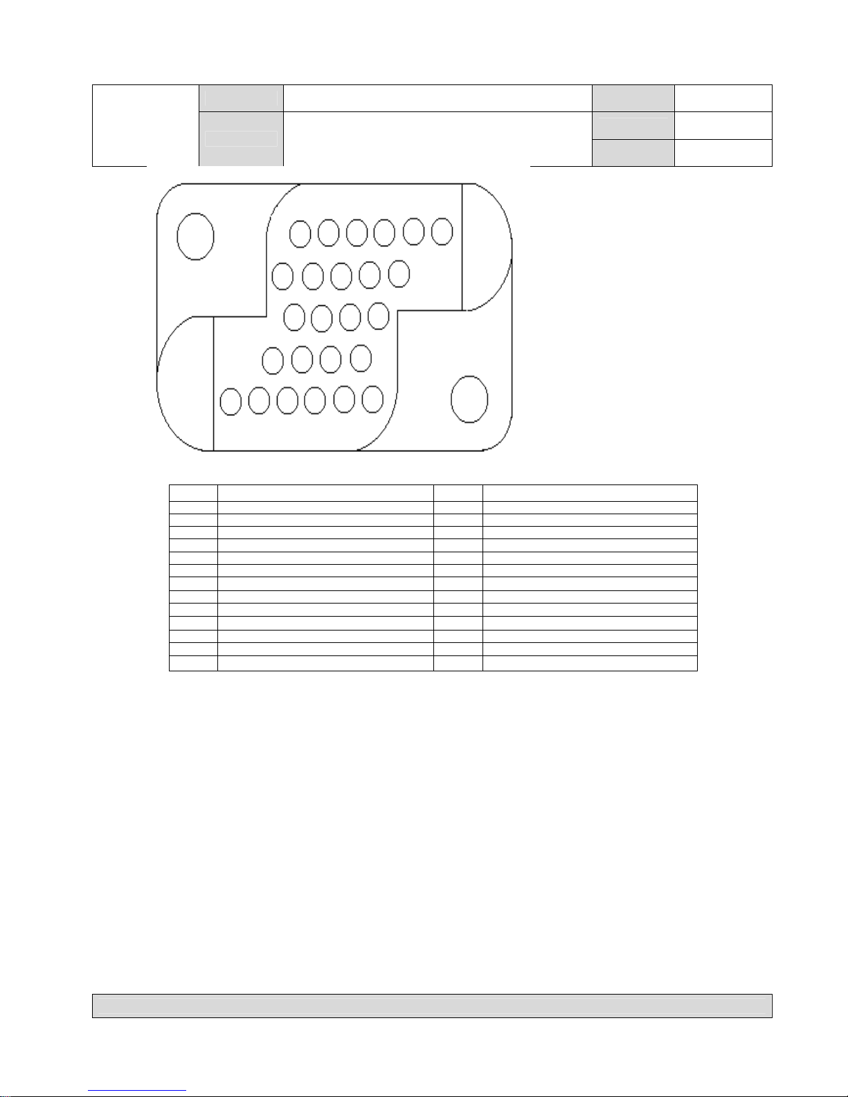
AMP 25pin connector
NO. DESCRIPTION NO. DESCRIPTION
1 VIDEO RED 14 MRESET
2 RED GND 15 NET GND
3 VIDEO GREEN 16 USB VCC
4 GREEN GND 17 USB D5 VIDEO BLUE 18 USB D+
6 BLUE GND 19 USB GND
7 SHIELD GND 20 NET13V
8 H-SYNC 21 +13VDC
9 V-SYNC 22 A GND
10 SCL 23 FRAME GND
11 SDA 24 AC LINE
12 NET RXD 25 AC NEUTRAL
13 NET TXD
6. CONTROLS AND ADJUSTMENTS
There are four switches on the control panel.
Adjustable controls allow the best display status for individual preferences.
6-1. Key Function
① MODE
MODE - Call the Main-Menu OSD.
② SEL/DEGAUSS
SEL – Select the function (sub-Menu OSD) on the Main- Menu OSD.
DEGAUSS – Do degaussing in the state that the OSD isn’t displayed.
③ DOWN/UP
-When the Main-Menu is displayed, you can search each function using
these keys.
-When the Sub-Menu is displayed (after selecting the function), you can
change each state of the screen using these keys.
TOVIS CO., LTD.
 Loading...