

Tovenco Prosecco Instruction Manual

Instructions Manual
Bruksanvisning
Brugsvejledning
Bruksanvisning
Käyttöohje

2
2
INDEX
RECOMMENDATIONS AND SUGGESTIONS.....................................................................................................................3
CHARACTERISTICS.............................................................................................................................................................4
INSTALLATION...................................................................................................................................................................... 6
USE......................................................................................................................................................................................16
MAINTENANCE...................................................................................................................................................................18
INNEHÅLL
REKOMMENDATIONER OCH TIPS...................................................................................................................................20
EGENSKAPER.....................................................................................................................................................................21
INSTALLATION.................................................................................................................................................................... 23
ANVÄNDING........................................................................................................................................................................33
UNDERHÅLL........................................................................................................................................................................35
INDHOLD
RÅD OG ANVISNINGER.....................................................................................................................................................37
APPARATBESKRIVELSE ................................................................................................................................................... 38
INSTALLATION.................................................................................................................................................................... 40
BRUG................................................................................................................................................................................... 50
VEDLIGEHOLDELSE.......................................................................................................................................................... 52
INNHOLD
ANBEFALINGER OG FORSLAG........................................................................................................................................ 54
EGENSKAPER.....................................................................................................................................................................55
INSTALLASJON................................................................................................................................................................... 57
BRUK ...................................................................................................................................................................................67
VEDLIKEHOLD.................................................................................................................................................................... 69
SISÄLTÖ
OHJEET JA SUOSITUKSET...............................................................................................................................................71
MITAT JA OSAT ..................................................................................................................................................................72
ASENNUS............................................................................................................................................................................ 74
KÄYTTÖ............................................................................................................................................................................... 84
HUOLTO .............................................................................................................................................................................. 86
EN
SE
DK
NO
FI
EN
3
3
RECOMMENDATIONS AND SUGGESTIONS
The Instructions for Use apply to several versions of this appliance. Accordingly, you may
find descriptions o f ind ividu al fea tures that do no t apply to your sp ecific appl iance .
INSTALLATION
• The manufacturer will not be held liable for any damages resulting from incorrect or improper installation.
• Check that the mains voltage corresponds to that indicated on the rating plate fixed to the
inside of the hood.
• For Class I appliances, check that the domestic power supply guarantees adequate
earthing.
Connect the extractor to the exhaust flue through a pipe of minimum diameter 120 mm.
The route of the flue mu st be as shor t as poss ible.
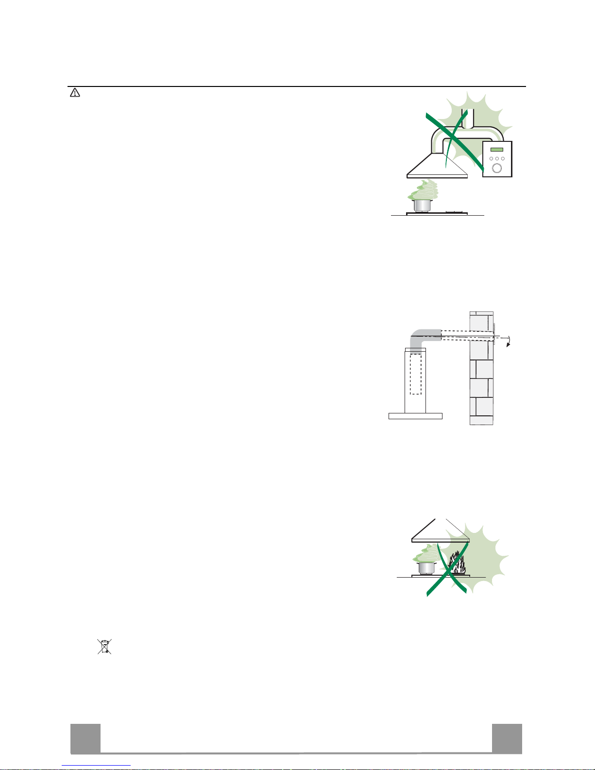
• Do not connect the extractor hood to exhaust ducts carrying combustion fumes (boilers,
fireplaces, etc.).
• If the extractor is used in conjunction with n on- elec trica l ap plia nces (e.g. g as bur ning a ppliances), a sufficient degree of aeration must be guaranteed in the room in order to prevent
the backflow of exhaust gas. The kitchen must have an opening communicating directly
with the open air in order to guarantee the entry of clean air. When the cooker hood is
used in conjunction with appliances supplied with energy other than electric, the negative
pressure in the room must not exceed 0,04 mbar to prevent fumes being drawn back into
the room by the cooker hood.
• In the event of damage to the power cable, it must be replaced by the manufacturer or by
the technical service d epar tment, in order to pr even t any r isks.
• If the instructions for installatio n for the g as hob specify a grea te r dis tance spec i fied above,
this has to be taken into account. Regulations concerning the discharge of air have to be
fulfilled.
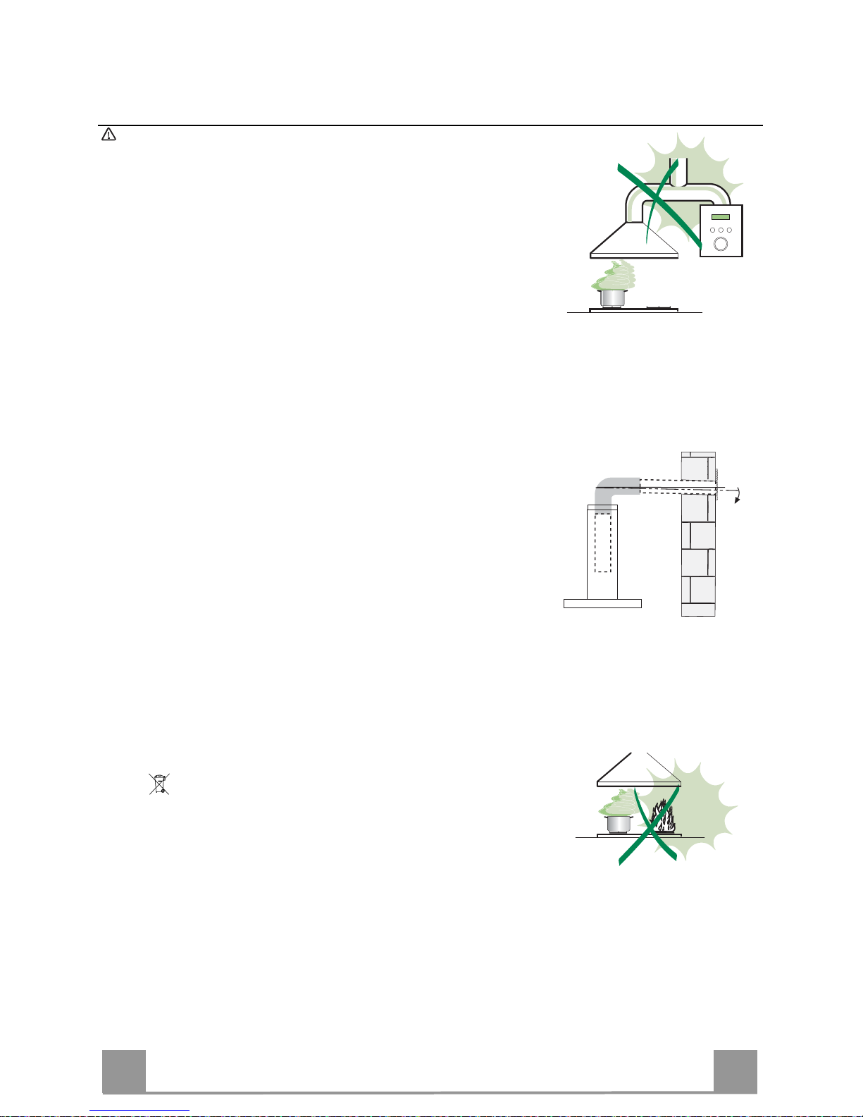
USE
• The extractor hood has been designed exclusively for domestic use to eliminate kitchen
smells.
• Never use the hood for purposes other than fo r which i t has been des igned.
• Never leave high naked flames under the hood when it is in operation .
• Adjust the flame intensity to direct it onto the bottom of the pan only, making sure that it
does not engulf the sides.
• Deep fat fryers must be continuously monitored during use: overheated oil can burst into
flames.
• Do not flambè under the range hood; r isk of fire
• This appliance is not intended for use by persons (including children) with reduced physical, sensory or mental capabilities, or lack of experience and knowledge, unless they have
been given supervision or instruction concerning use of the appliance by a person responsible for their sa fety .
• Children should be supervised to ensure that th ey do not play with the applian ce.
• “ CAUTION: Accessible parts may bec ome hot when used wi th co oking ap pliances .”.
MAINTENANCE
• Switch off or unplug the appliance from the mains supply before carrying out any maintenance work.
• Clean and/or replace the Fil ters after the sp ecified time p eriod ( Fire ha zard) .
• Clean the hood using a damp cloth and a neutral liquid detergent.
The symbol on the product or on its packaging indicates that this product may not be treated as household waste. Instead it shall be
handed over to the applicable collection point for the recycling of electrical and electronic equipment. By ensuring this product is disposed of
correctly, you will help prevent potential negative consequences for the environment and human health, which could otherwise be caused by
inappropriate waste handlin g of t his p roduct. F or mo re de tailed i nfo rmatio n abou t recyc ling of this p roduct , pl ease contact your local city o ffice, y our
household waste disposal servic e or the shop w here you purchased the pr oduct
.
2°
EN
4
4
CHARACTERISTICS
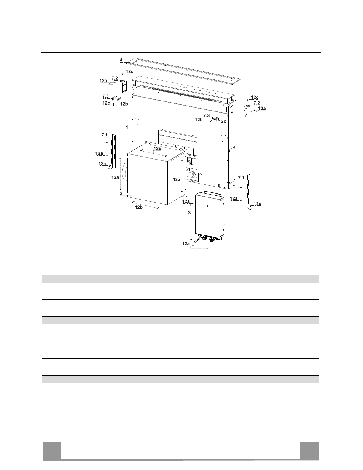
Components
Ref. Q.ty Product Components
1 1 Hood Canopy complete with: Controls, Light, Filters
2 1 Motor unit
3 1 Electric unit
4 1 Front Frame
Ref. Q.ty Installation Components
7.1 2 Splashback Fixing Bracket
7.2 2 Hob Fixing Bracket
7.3 2 Side Bracket
12a 16 Screws 3.5 x 9.5
12b 6 Screws M4 x 8
12c 6 Screws 4 x 15
Q.ty Documentation
1 Instruction Manual
EN
5
5
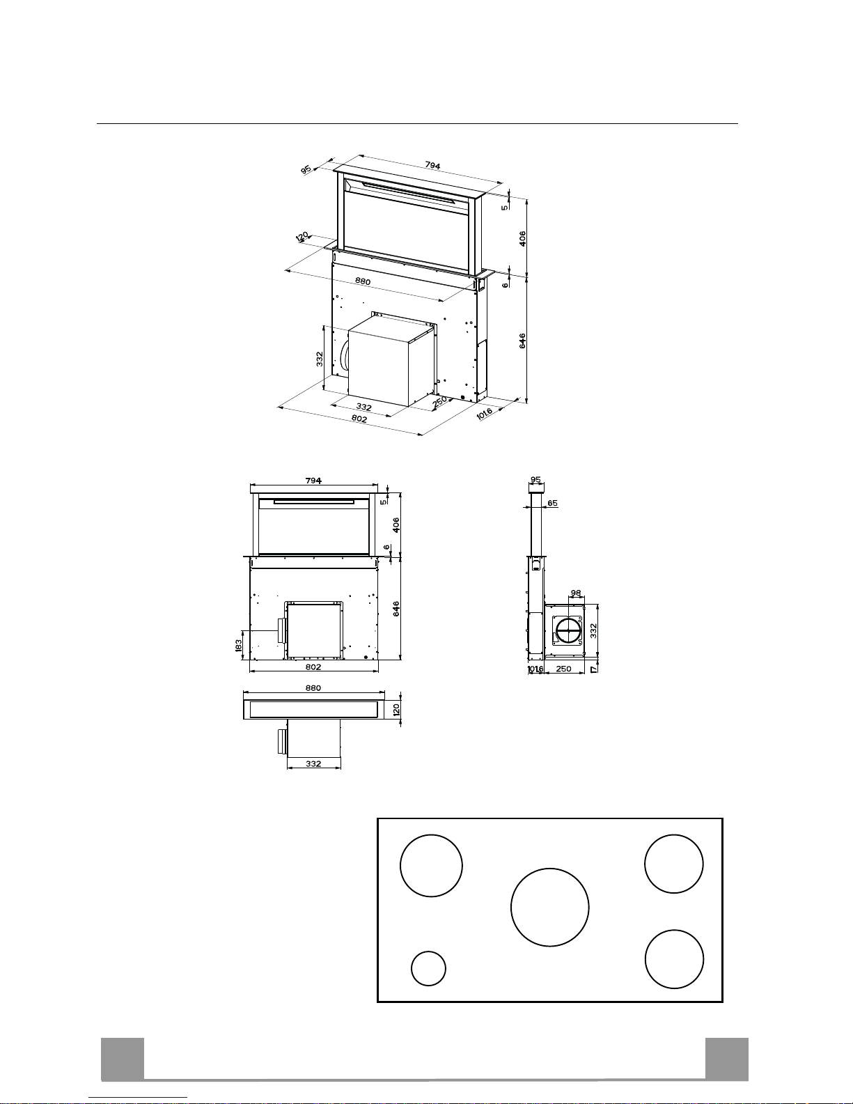
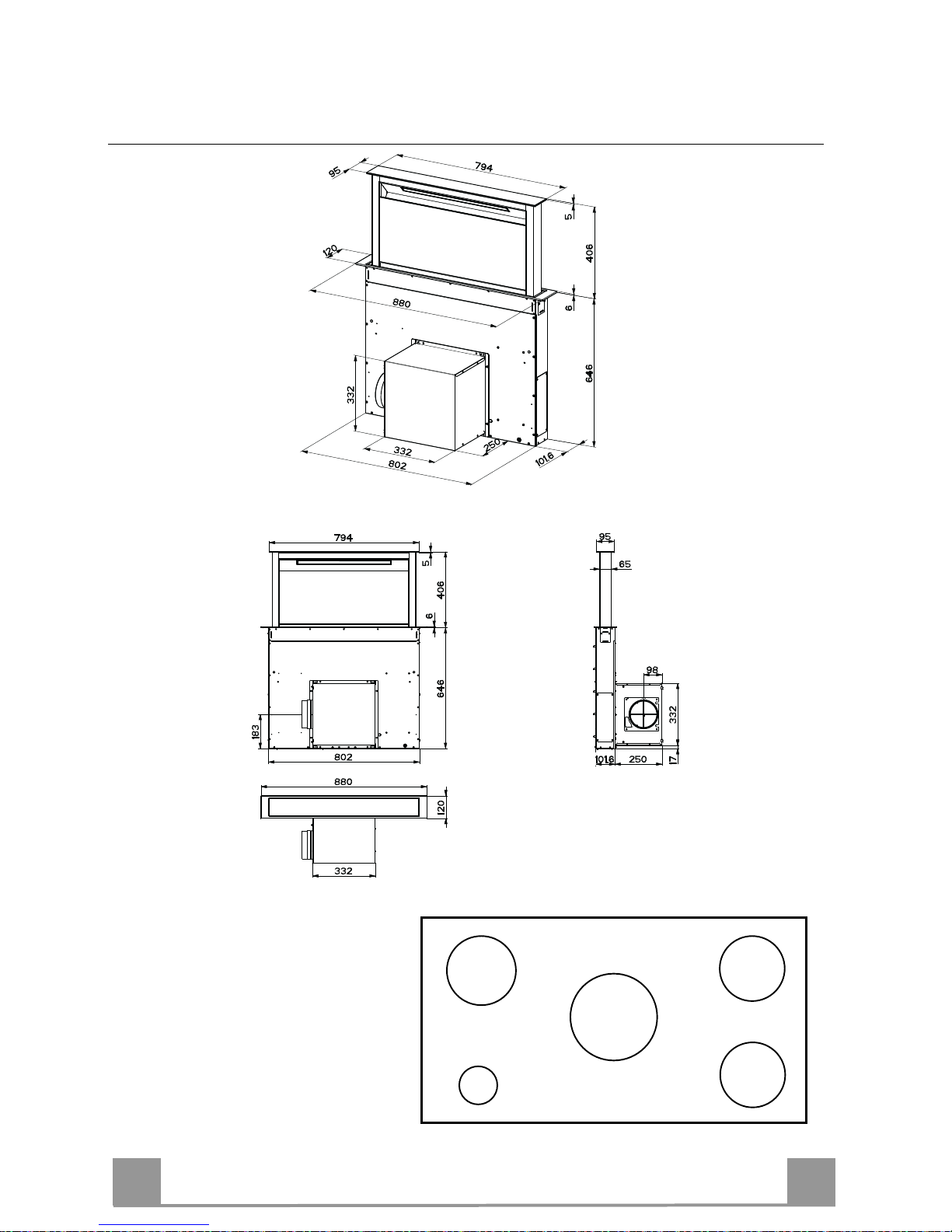
Dimensions
This Cooker hood can be used in
conjunction with a Gas Cook Top
having the following characteristics:
• Maximum power 12,4 kW
• 5 fire like the picture
2,6 kW
5 kW
1,9 kW
1,9 kW
1 kW
EN
6
6
INSTALLATION
This Hood is set up to be fitted inside the kitchen unit in:
• Ducting version: Evacuation to the outside.
• Recirculation version: Internal recirculation.
Sequence of operations - Installation
• Drilling the Support Surface and Fitting the Hood
• Connections
• Functional Check
• Disposal of Packaging
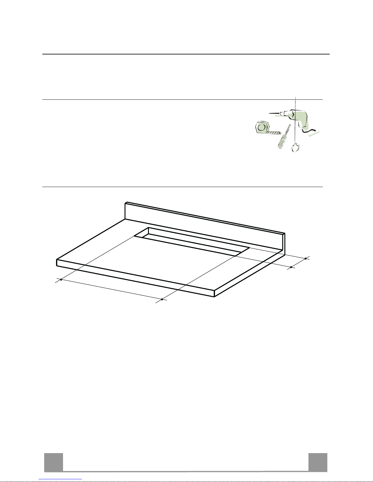
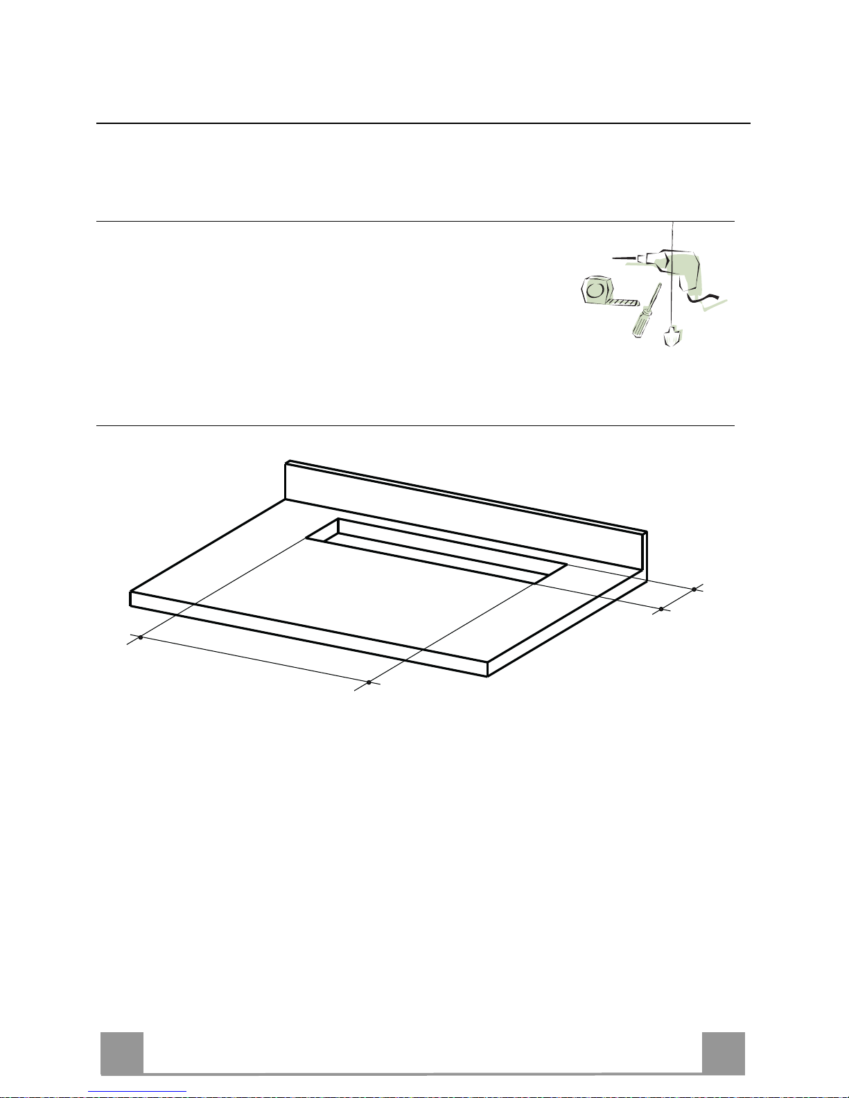
Drilling the Support Surface
X
812
Warning
Once the Support surface has been drilled the Hood Canopy can be installed in two ways:
• By inserting the Hood Canopy from below ( X = 106 mm ).
• By inserting the Hood Canopy from above ( X = 113 mm ).
IMPORTANT
The minimum distance between the opening for the hob and the one for the hood must be of at
least 3-5 cm according to the strength of the material used for the working top.
EN
7
7
7.2
12a
7.2
12a
A
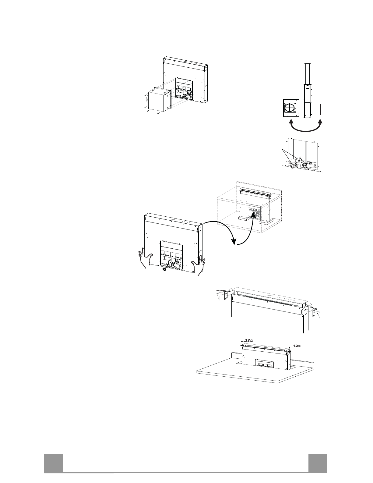
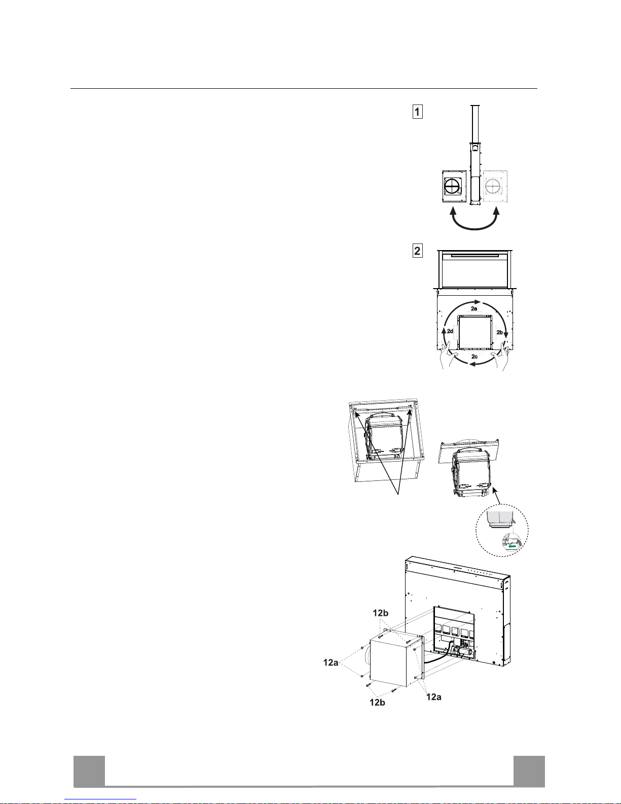
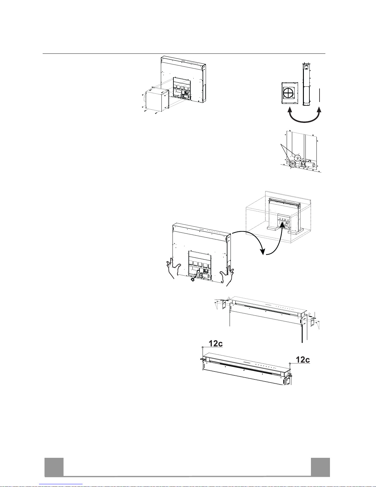
Inserting the Hood Canopy into the support surface from below
• The Hood is built ready for
front installation of the Motor Unit.
• If the kitchen unit is arranged differently and the Motor Unit has to be
fitted on the back, the Plug already fitted on the back of the Hood Canopy must be removed and replaced at the front, and the Cable with cable
raceway for connection of the Motor must also be repositioned using the
slot provided on each side (A).
Before proceeding, the Motor Unit must be fixed to the Hood Canopy
(see paragraph on Fixing the Motor Unit).
• Insert the Hood Canopy
from below into the
support worktop, drilled
as described above.
• With the aid of a support, lift the Hood Canopy until the front
comes out of the Worktop.
• Insert the Brackets 7.2, as indicated in the
figure, into the slots provided and fix them
with the screws 12a provided.
• Centre the Hood Canopy with respect to the
Cooking Hob slot.
• Using the 2 screws 12c provided, fix the
Hood Canopy to the worktop and remove
the supports.
Warning:
If the cooker top is made from a material that does not allow the screws 12c to be inserted, use
a small amount of silicone to glue the Brackets 7.2 to the top and allow it to dry completely
before proceeding with installation
EN
8
8
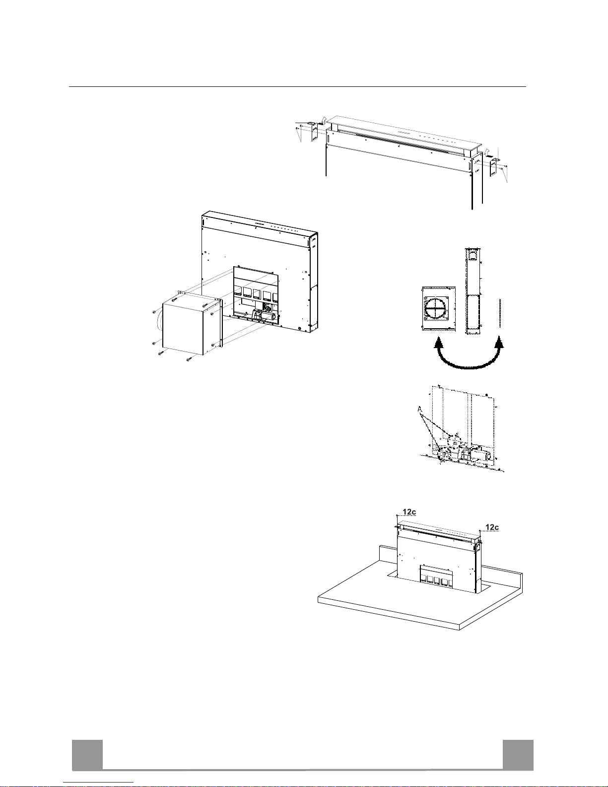
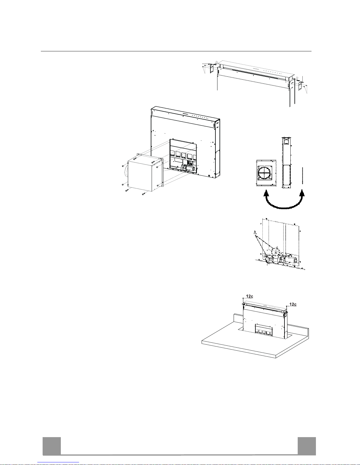
Inserting the Hood Canopy into the support surface from above
• Insert the Brackets 7.2, as indicated in the figure, into the slots
provided and fix them with the
screws 12a provided.
• The Hood is built
ready for front in-
stallation of the
Motor Unit.
• If the kitchen unit is arranged differently and the Motor Unit
has to be fitted on the back, the Plug already fitted on the back
of the Hood Canopy must be removed and replaced at the front,
and the Cable with cable raceway for connection of the Motor
must also be repositioned using the slot provided on each side
(A).
• Insert the Hood Canopy into the cooker top,
drilled as described above.
• Centre the Hood Canopy with respect to the
Cooking Hob slot.
• Fix the Hood Canopy with the 2 screws 12c
provided.
Warning:
If the cooker top is made from a material that does not allow the screws 12c to be inserted, use
a small amount of silicone to glue the Brackets 7.2 to the top and allow it to dry completely
before proceeding with installation.
7.2
12a
7.2
12a
EN
9
9
12c
12a
7.1
12a
7.1
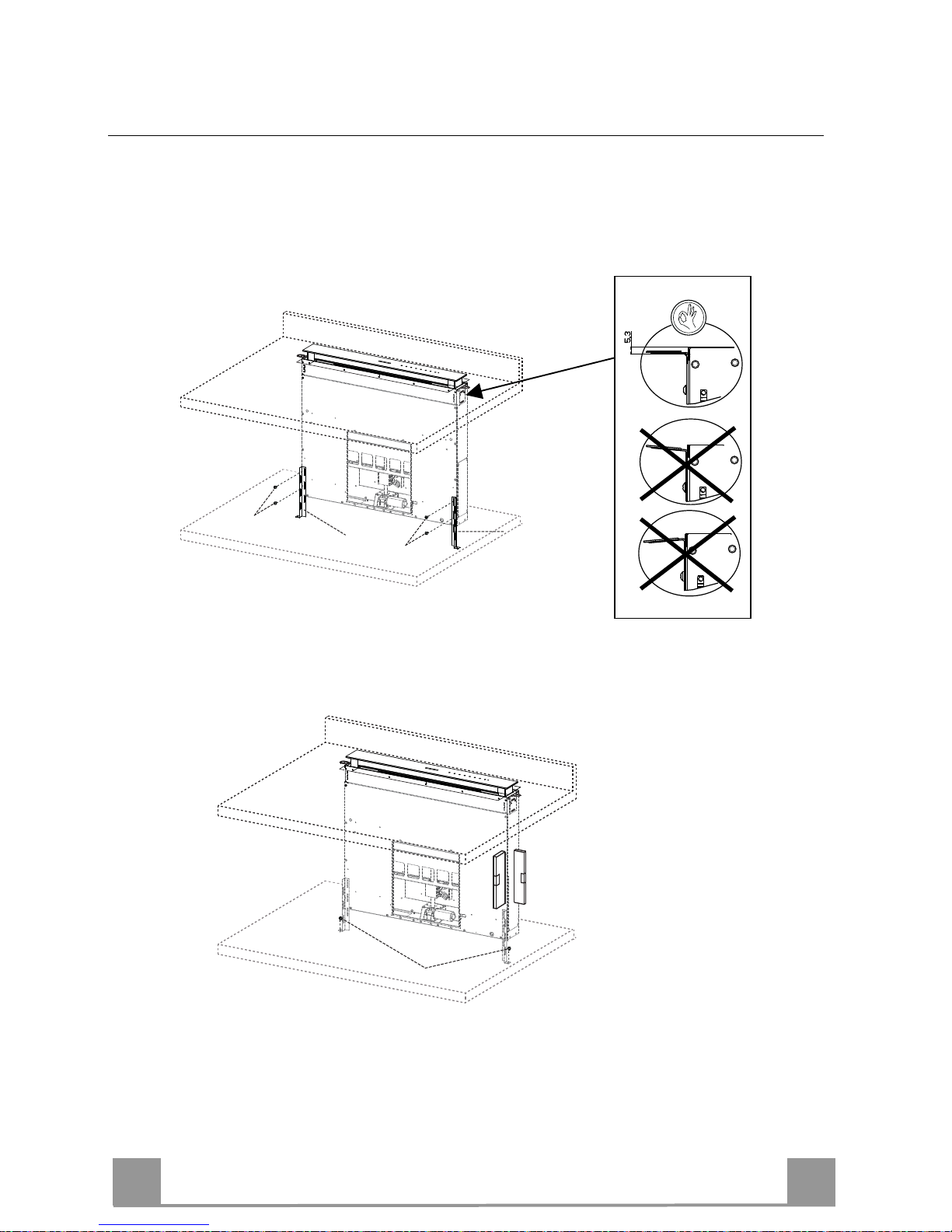
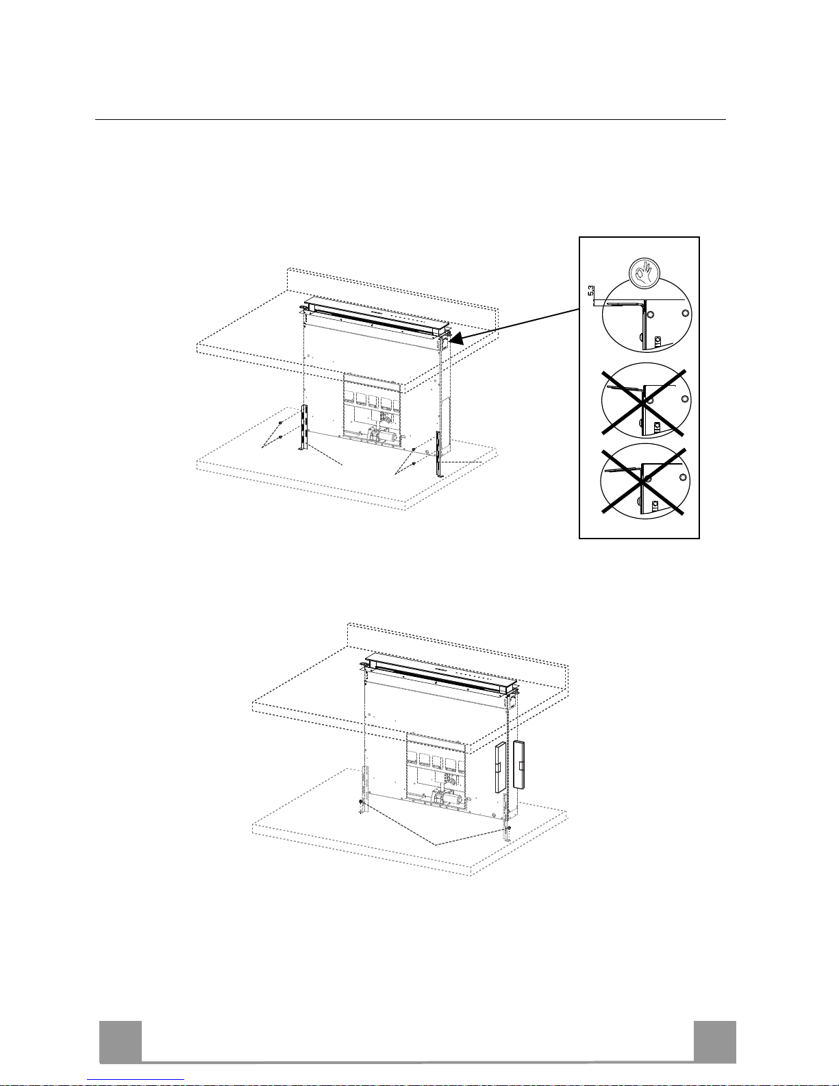
Fixing the Lower Brackets
• Screw the brackets 7.1 to the front of the Hood Canopy using the screws 12a provided.
• Before tightening the Brackets completely, make all the adjustments to allow them to rest on
the lower base of the worktop to avoid deformation of the upper brackets 7.2 as shown in the
figure.
• With the aid of a spirit level, set the Hood Canopy level vertically and fix it to the Lower
Surface using 2 screws 12c provided.
• Tighten the screws 12a completely.
EN
1
10
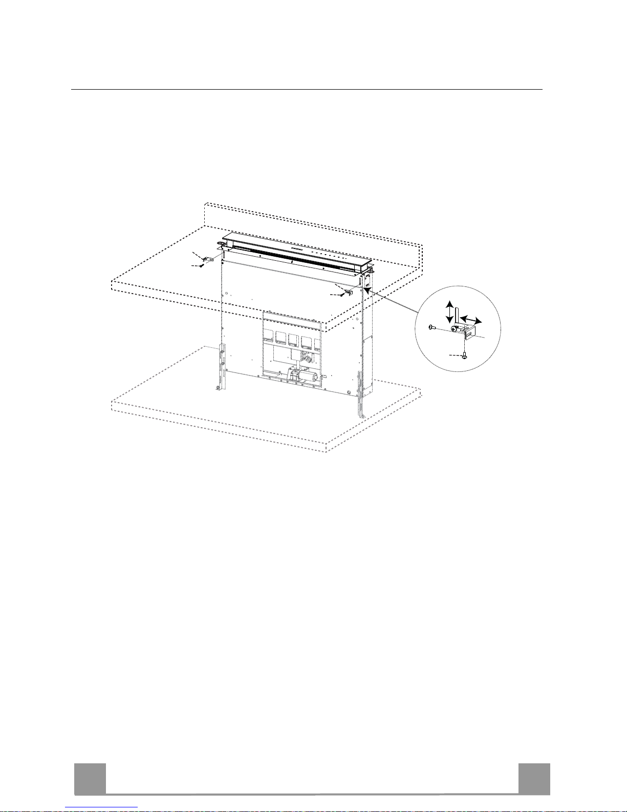
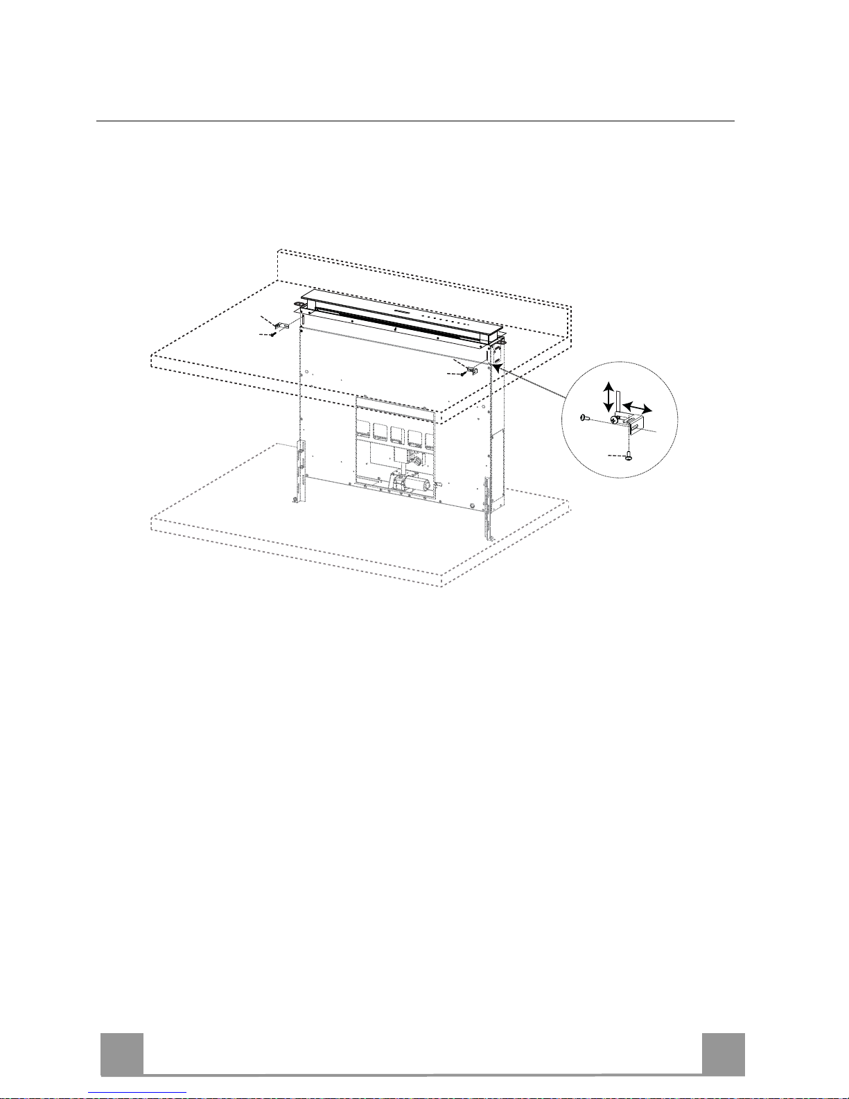
Fixing the Squaring Brackets
• Screw the brackets 7.3 to the Hood Canopy using the screws 12b provided, without
tightening completely.
• Using the screws 12c provided, fasten the other part of the brackets 7.3 either to the side
walls of the unit or to the lower part of the cooker top.
12b
7.3
12b
7.3
12c
• Tighten the screws 12c and 12b completely.
EN
1
11
A
Fixing the Motor Unit
• Installation of the Motor Unit (1) at the front or rear must be de-
cided according to the position of the Kitchen unit, making sure
that the plug is properly positioned.
• Subsequently, according to where the air outlet opening has been
created on the unit, the Motor Unit can be turned by 90° at a time
so as to allow the air to come out on all 4 sides in correspondence
with the opening in Unit (2).
• Remove the Motor Unit from the support by
unfastening the 2 screws (A).
• Connect the connector from the Hood Canopy to
the Motor Unit connection.
• Replace the Motor Unit in the support using the
2 screws removed as described above.
• Screw the Motor Unit to the Hood Canopy using
the screws 12a and 12b provided as shown in the
figure.
EN
1
12
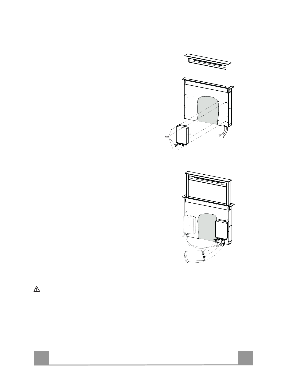
Fixing the Electric Unit
• Connect the Electric cables that come out of the lower
right hand part of the Hood Canopy to the Connectors
on the Electric unit.
• Each cable connector has a corresponding connector
on the Electric Unit, so take care not to make mistakes
when connecting up.
• Fix the Electric Unit to the Hood Canopy using the
screws 12a provided.
• The position indicated in the figure is only an option,
as if necessary it may also be fitted on the left of the
Hood Canopy or even left free on the base of the unit
if there are no structural or safety problems involved.
Warning..: Do not install the produc t in such a way that the wiring box is in contact with the floor.
EN
1
13
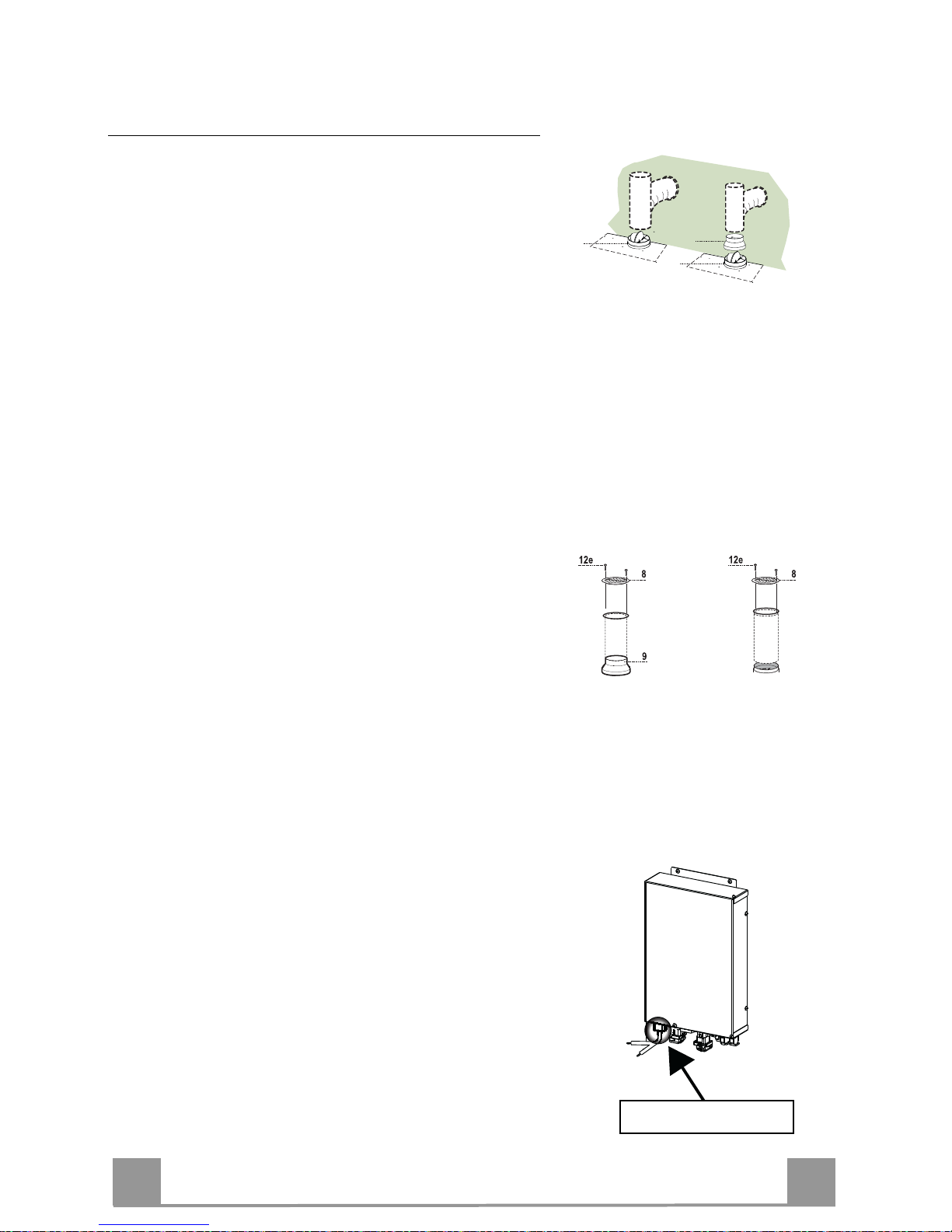
Connections
DUCTED VERSION AIR EXHAUST SYSTEM
When installing the ducted version, connect the hood to
the chimney using either a flexible or rigid pipe ø 150 or
120mm, the choice of which is left to the installer.
To install a ø 150 pipe
• To install the dumper 10
• Fix the pipe in position using sufficient pipe clamps
(not supplied).
To install a ø 120 pipe
• To install a ø 120 mm air exhaust connection, insert
the reducer flange 9 on the dumper 10.
• Fix the pipe in position using sufficient pipe clamps
(not supplied).
• Remove any activated charcoal filters.
ø 120
ø 150
10
10
9
AIR OUTLET – RECIRCULATION VERSION
• Connect the Flange to the air outlet opening using a
rigid or flexible pipe of ø120 or 150 mm.
• To connect using a ø120 mm pipe, insert the reduction Flange 9 onto the Hood canopy outlet.
• Fasten the pipe using suitable pipe clamps. The materials required to do so are not provided.
• Fix the directional Grid 8 on the outlet, using 2 screws
12e (2.9 x 9.5) provided.
• Make sure that the activated charcoal filters are present (see paragraph on Activated Charcoal Filter
Maintenance).
ELECTRICAL CONNECTION
• Connect the hood to the mains through a two-pole
switch having a contact gap of at least 3 mm..
APPLIANCE IN LET
EN
1
14
Warning..:
Handle with
care
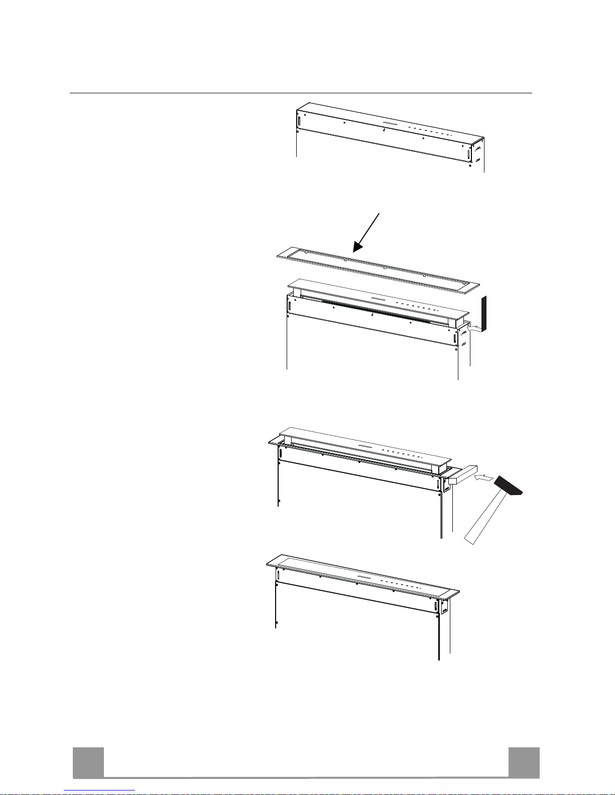
Fitting the Front element
• Lift the mobile hood canopy
(see paragraph on Use) by just a
few centimetres.
• To stop movement, simply
press down on the mobile canopy as it lifts up.
Warning: Never block the slid-
ing door when it is opening or
closing, except during the operations required to fit the
frame.
• Remove the sponge guards
from the corners of the glass.
• Take the front Frame and insert
it from above, making sure that
its tabs insert into the slots provided on the Hood and sliding it
to the left.
Warning..: All the tabs must be
inserted.
• Use a tool (hammer) to tap all
along the front Frame from
right to left until it is completely flush.
A piece of wood or similar
element can be inserted between the hammer and the front
Frame to prevent any damage.
• Please refer to the paragraph on
Use for indications of how to
return the mobile canopy to the
Standard position.
EN
1
15
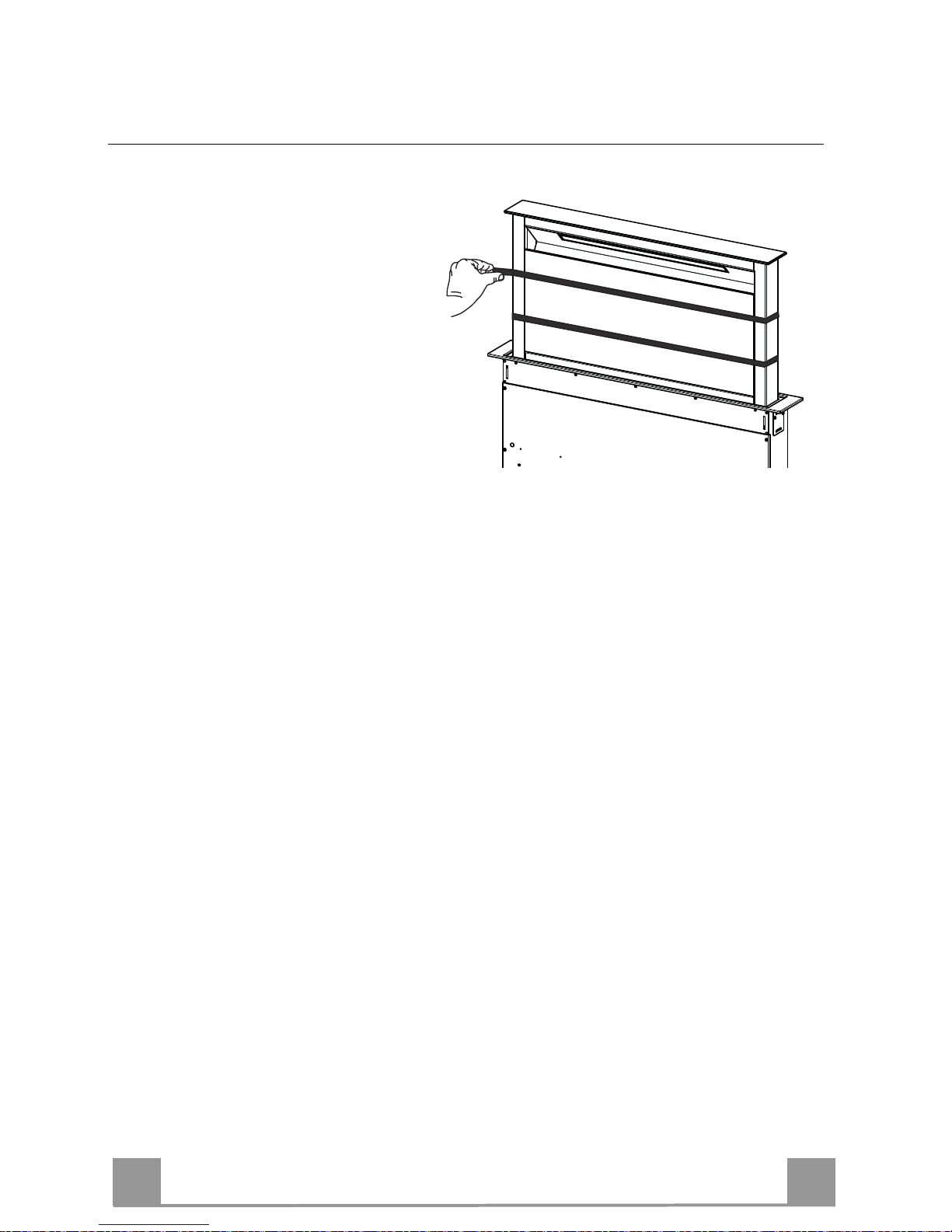
Surround Suction Panel
• Open the Hood Door (see
USE).
• Remove the 2 strips of adhesive
tape fastening the panel during
transport.
EN
1
16
USE
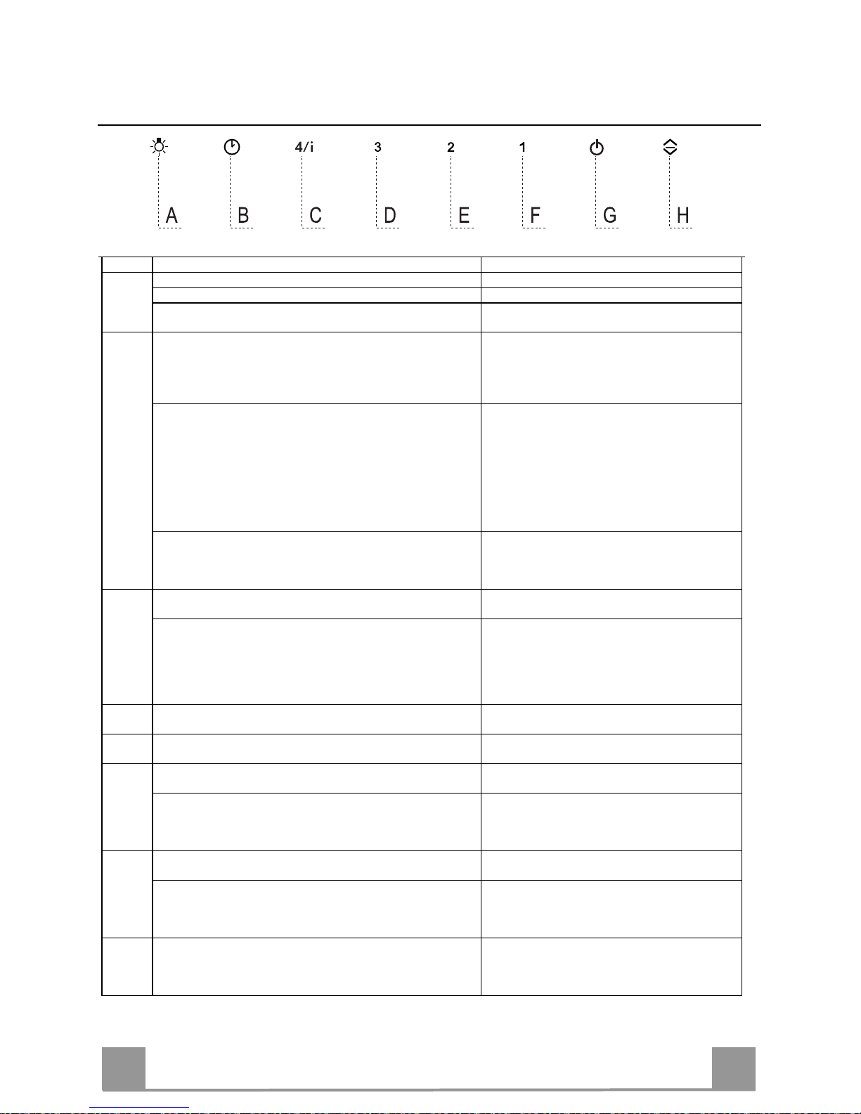
Control panel
Button Function LED button
A The button only works when the door is open.
Press Briefly = Turns the Lights On/Off at maximum intensity.
Press and hold for 2 Seconds = Turns the Courtesy Lights
On/Off.
B Only works with the Door Open.
Press briefly = Activates/Deactivates Delay mode, causing automatic shutdown of the Motor and the Lighting system from any
speed with a 30’ delay. It is disabled by pressing the same button
again, turning the motor off or closing the door.
LED Button B+ Button for the set Speed are lit.
Works both with the Door Closed and Open.
Press and hold for 2 Seconds = With the filter alarm triggered the
Filter Alarm is Reset. These indications are only visible when the
motor is turned off.
Fixed LED button:
Indicates the need to wash the metal grease filters.
The alarm is triggered after the Hood has been in
operation for 100 working hours.
Flashing LED button:
Indicates the need to change the activated charcoal
filters, and also to wash the metal grease filters. The
alarm is triggered after the Hood has been in
operation for 200 working hours.
Works both with Door Closed and Open with Motor + Lights =
Off.
Press and hold for 4 Seconds = Enables/disables the Keyboard
lock.
All the LED buttons flash twice. During the Lock
the LED buttons light up in sequence.
C Only works with the Door Open.
Press briefly = Activates speed four.
Fixed LED button
Only works with the Door Open.
Press and hold for 2 seconds = Enables/Disables the Intensive
speed. This speed is timed to run for 10 minutes. At the end of this
time the system will return to the speed set previously.
It is disabled by pressing the same button again, turning the motor
off or closing the door.
Flashing LED button
D Only works with the Door Open.
Activates speed three.
Fixed LED button
E Only works with the Door Open
Activates/Deactivates speed two.
Fixed LED button
F Only works with the Door Open.
Press briefly = Activates/Deactivates speed one.
Fixed LED button
Door Open or Closed
Press and hold for 2 Seconds = Enables/Disables the Activated
Charcoal Filter Alarm with the Motor turned off and no Filter
Alarm triggered.
LED button B flashes twice = Activated Charcoal
filter Alarm Activated
LED button B flashes once = Activated Charcoal
filter Alarm Deactivated
G Door Open
Press briefly = Turns the Motor off
LED button goes out
Door Open or Closed
Press and hold for 2 Seconds with Motor and Lights Off =
Enables/Disables the Remote control.
LED button G + F flashes twice = Remote control
Enabled
LED button G + F flashes once = Remote control
Disabled
H Door Open = Closes the Door + Lights and Motor Off
Door Closed = Opens the Door + Lights and Motor On.
Warning: If the Door remains partially open for any reason, press
the Button to complete the opening or closing cycle.
EN
1
17
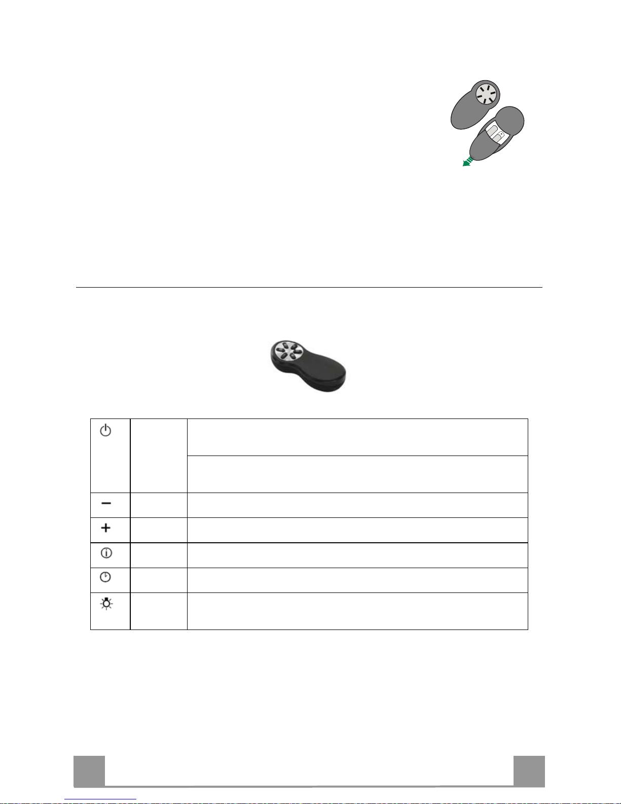
REMOTE CONTROL (OPTIONAL)
The appliance can be controlled using a remote control powered by a
1.5 V carbon-zinc alkaline batteries of the standard LR03-AAA type
(not included).
• Do not place the remote control near to heat sources.
• Used batteries must be disposed of in the proper manner.
Remote control panel
Warning..: The remote control receiver is deactivated when first supplied. To activate it, see the para-
graph Use Function of Button G.
Motor
Door Closed:
Opens the door, turns the motor on at speed one and turns the lights on at
maximum intensity.
Door Open:
Brief pressure: Motor On / Off
Pressed for 2 Seconds: Closes the Door and Motor + Lights = Off
Only with Door Open:
Decreases the working speed each time it is pressed.
Only with Door Open:
Increases the working speed each time it is pressed.
Intensive
Only with Door Open:
Activates the Intensive function
Delay
Only with Door Open:
Activates the Delay function
Light
Only with Door Open:
Brief pressure: Lights On / Off
Pressed for 2 Seconds: Courtesy lights On / Off
EN
1
18
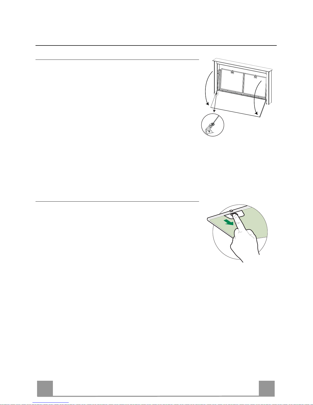
MAINTENANCE
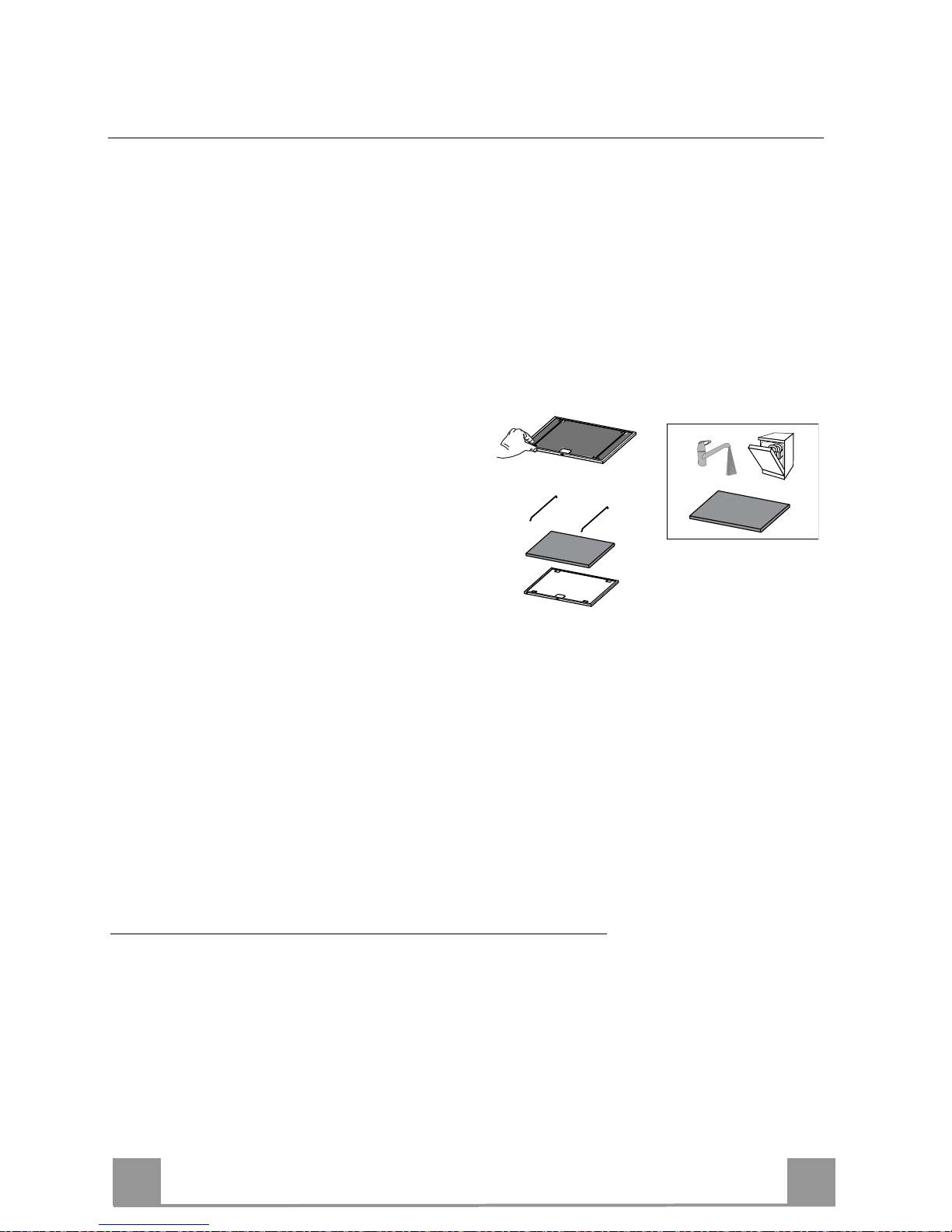
Cleaning the Comfort Panels
• Open the Comfort Panel by pulling it at the top.
• Unhook the security chain by opening the spring catch.
• Disconnect the panel from the hood canopy.
• The comfort panel must never be washed in the dishwasher.
• Clean the outside with a damp cloth and neutral detergent.
• Clean the inside using a damp cloth and neutral detergent; do
not use wet cloths or sponges, or jets of water; do not use
abrasive substances.
• On completing the operation, hook the panel and the spring
catch up to the hood canopy again and close it.
Metal grease filters
These can also be washed in the dishwasher, and need to be
cleaned whenever button B lights up or at least once every 2
months use, or more frequently if use is particularly intensive.
Resetting the alarm signal
• Turn the Lights and the Suction Motor off.
• Press and hold button B for 2 seconds.
Cleaning the Filters
• Open the Door (see USE).
• Open the Comfort panel by pulling it.
• Remove the Filters one at a time, pushing them towards the
back of the unit and at the same time pulling downward.
• Wash the Filters without bending them, and leave them to dry
completely before replacing. (If the surface of the filter
changes colour as time goes by, this will have absolutely no
effect on the efficiency of the filter itself.)
• Replace, taking care to ensure that the handle faces forwards.
• Close the Comfort panel.
EN
1
19
Activated Charcoal Filter (Recirculation Version)
Can be washed in the dishwasher. It must be washed when button B flashes or at least once
every 4 months, or more frequently if use is particularly intense. Guaranteed to operate after
washing for up to a maximum of 5 times before requiring replacement. The Alarm signal, if it
has been activated, only appears when the Suction motor is turned on.
Activating the alarm signal
• In Recirculation Version Hoods, the Filter Saturation Alarm must be activated on installation or at a later date.
• Turn the Lights and the Suction Motor off.
• Press and hold button F for 2 seconds:
• LED B flashes twice – Activated Charcoal Filter saturation alarm ACTIVATED.
• LED B flashes once – Activated Charcoal Filter saturation alarm DEACTIVATED.
CHANGING THE ACTIVATED CHARCOAL FILTER
Resetting the alarm signal
• Turn the Lights and the Suction Motor off.
• Press and hold button B for 2 seconds.
Changing the Filter
• Remove the comfort panel.
• Remove the Metal grease filters.
• Remove the metal filter stops from the grease
filter and clean the saturated activated
charcoal odour filter.
• Replace the clean activated charcoal odour
filter, hooking it back up to the grease filter
using the metal filter stops.
• Replace the Metal grease filters.
• Close the comfort panel.
Lighting unit
Warning: This appliance is fitted with a white LED lamp classed as 1M
according to EN 60825-1: 1994 + A1:2002 + A2:2001 standards; maximum optical power emitted @439nm: 7µW. Do not look directly at the
light through optical devices (binoculars, magnifying glasses…).
• For replacement contact technical support. ("To purchase contact technical support")
SE
2
20
REKOMMENDATIONER OCH TIPS
Denna bruksanvisning är förutsedd för flera versioner av apparaten.
Det är möjligt att vissa enskilda utrustningsdetaljer, inte berör din apparat.
INSTALLATION
• Tillverkaren åtar sig inget ansvar för fel som beror på felaktig eller olämplig installation.
• Kontrollera att matningsnätets spänning motsvarar den som anges på märkskylten inuti köksfläkten.
• För Klass I-apparater, kontrollera att matningsnätet ger effektiv jordning.
• Anslut fläkten till frånluftkanalen via ett rör med en diameter på minst 120 mm. Anslutningsröret skall hållas
så kort som möjligt.
• Anslut inte köksfläkten till frånluftkanaler som leder förbränningsgaser (från pannor, eldstäder etc.).
• Om fläkten används tillsammans med icke-elektriska spisar (t.ex. gasspisar) måste tillräcklig ventilation
garanteras i lokalen för att förhindra backflöde av förbränningsgaser. Köket måste ha ett tilluftdon med direkt
anslutning mot ytterluft för att garantera inflöde av friskluft. Korrekt är riskfri användning säkerställas när det
maximala undertryck i lokalen inte överstiger 0,04 mbar
• I händelse av skada på kabeln, måste den bytas av tillverkaren eller av den tekniska serviceavdelning, för
att undvika risker.
• Om installationsanvisningarna för matlagningsanordningen med gas anger att ett större avstånd än det
ovan angivna är nödvändigt måste det beaktas. Man måste följa alla regler om luftutsläpp.
ANVÄNDNING
• Köksfläkten är uteslutande avsedd för hemanvändning, för att eliminera köksos.
• Använd aldrig köksfläkten för andra ändamål än det avsedda.
• Undvik höga flammor under köksfläkten medan fläkten är i drift.
• Justera gaslågan så att flammorna endast berör kokkärlets undersida och inte tränger upp längs dess
sidor.
• Fritöser måste övervakas kontinuerligt under användning: Överhettad olja kan fatta eld.
• Köksfläkten skall inte användas av barn eller personer som inte är insatta i korrekt användning.
• Apparaten är inte avsedd att användas av barn eller handikappade personer utan övervakning.
• Tillaga inga flamberade maträtter under köksfläkten, då det finns risk för eldsvåda
• Denna apparat får inte användas av personer (inklusive barn) med nedsatta fysiska, sensoriska eller mentala förmågor, eller av personer utan erfarenhet och kunskap, om inte de är kontrollerade eller instruerade
om användningen av apparaten av personer ansvariga för deras säkerhet.
• Barn ska övervakas för att säkerställa att de inte leker med apparaten.
• “VARNING: De åtkomliga delarna kan bli mycket varma om de används med matlagningsapparater.”.
UNDERHÅLL
• Stäng av apparaten eller skilj den från matningsnätet innan något underhållsarbete utförs.
• Rengör och/eller byt filtren med angivet intervall (Risk för eldsvåda).
• Rengör köksfläkten med en fuktig trasa och neutralt flytande diskmedel.
Symbolen på produkten eller embal laget anger att pr odukten i nte f år hant eras s om hus hållsa vfall. Den skall i stället lämnas in på uppsamlingsplats för återvinning av el- och elektronikkomponenter. Genom att säkerställa att produkten hanteras på rätt sätt bidrar du till att förebygga eventuellt
negativa miljö- och hälsoeffekter som kan uppstå om produkten kasseras som vanligt avfall. För
ytterligare upplysningar o m återvinnin g bör du kont akta lokala myndi gheter ell er sophämtnin gstjänst
eller affären där du köpte varan.
2°

SE
2
21
EGENSKAPER
Komponenter
Ref. Antal Produktkomponenter
1 1 Köksfläktsstomme komplett med: Reglage, Belysning, Filter
2 1 Motorenhet
3 1 Elenhet
4 1 Frontram
Ref. Antal Installationskomponenter
7.1 2 Fastsättningskonsol på väggplåten
7.2 2 Fastsättningskonsol på stödplanet
7.3 2 Sidokonsol
12a 16 Skruvar 3,5 x 9,5
12b 6 Skruvar M4 x 8
12c 6 Skruvar 4 x 15
Antal Dokumentation
1 Bruksanvisning
SE
2
22
Mått
Den här apparaten kan användas i
kombination med en gashäll med följande egenskaper:
• Max. effekt 12,4 kW
• 5 brännare placerade som på följande
figur
2,6 kW
5 kW
1,9 kW
1,9 kW
1 kW
SE
2
23
INSTALLATION
Den här köksfläkten är förbredd för att installeras invändigt köksmöbeln i:
• Utsugande version: Extern avledning.
• Filtrerande version: Intern återcirkulering.
Följd av installationsmoment
• Borrning av stödplan och montering av köksfläkt
• Anslutningar
• Funktionskontroll
• Bortskaffande av förpackningsmaterial
Borrning i stödplan
X
812
Varning
När en gång stödplanet har borrats är det möjligt att installera köksfläktsstommen på två sätt:
• Sätta i köksfläktsstommen nerifrån ( X = 106 mm ).
• Sätta i köksfläktsstommen uppifrån ( X = 113 mm ).
VIKTIGT
Min. avståndet emellan det borrade hålet för spishällen och det för utsugningsapparaten ska
vara minst 3-5 cm beroende på moståndet av materialet använt för den övre delen.
SE
2
24
7.2
12a
7.2
12a
A
Isättning av köksfläktsstommen i stödplanet nerifrån
• Köksfläkten är förberedd för
frontmontering av motorenheten.
• Om köksmöbelns placering är annorlunda är det nödvändigt att se
till att montera motorenheten på baksidan, pluggen som redan är
fästad på baksidan av köksfläktsstommen ska demonteras och
återmonteras framtill, återplacera även kabeln med kabelförskruvning för anslutning av motorn genom att använda det avlånga hålet förberett på varje sida (A).
Innan du fortsätter ska motorenhten fästas på kökfläktsstommen
(Se avsnitt Fastsättning av motorenhet).
• Sätt i köksfläktsstommen underifrån i stödplanet som tidigare
har borrats.
• Med hjälp av ett stöd lyft köksfläktsstommen tills fronten inte
kommer ut ur stödplanet.
• Sätt i konsolerna 7.2, som anges på figuren,
i de tillhörande avlånga hålen och fäst dem
med de medföljande skruvarna 12a.
• Centrera köksfläktsstommen i förhållande
till spishällens avlånga hål.
• Fäst köksfläktsstommen med 2 medföljande skruvar 12c och ta bort stöden.
Varning:
Om på grund av spishällens material det inte är möjligt att skruva fast skruvarna 12c, använd
en liten mängd silicon för konsollerna 7.2 på stödplanet och låt det torka ordentligt innnan du
forstätter med installationen.
SE
2
25
7.2
12a
7.2
12a
Isättning av köksfläktsstommen i stödplanet uppifrån
• Sätt i konsolerna 7.2, såsom anges på figuren, i
de tillhörande avlånga hålen och fäst dem med
de medföljande skruvarna 12a.
• Köksfläkten är förberedd för frontmontering av motorenheten.
• Om köksmöbelns placering är annorlunda är det nödvändigt att se
till att montera motorenheten på baksidan, pluggen som redan är
fästad på baksidan av köksfläktsstommen ska demonteras och
återmonteras framtill, återplacera även kabeln med kabelförskruvning för anslutning av motorn genom att använda det avlånga hålet förberett på varje sida (A).
• Sätt i köksfäktsstommen i den tidigare borrade
spishällen.
• Centrera köksfläktsstommen i förhållande till
spishällens avlånga hål.
• Fäst köksfläktsstommen med de medföljande 2
skruvarna 12c.
Varning:
Om på grund av spishällens material det inte är möjligt att skruva fast skruvarna 12c, använd
en liten mängd silicon för konsollerna 7.2 på stödplanet och låt det torka innan du forstätter
med installationen.
SE
2
26
Fastsättning av undre konsoler
• Fäst konsolerna 7.1 på framsidan av köksfläktsstommmen med de medföljande skruvarna
12a.
• Innan du slutligen drar åt konsolerna utför regleringar som möjliggör för konsolerna att
stödja sig på basen av det undre stödplanet och undika deformation av de övre konsolerna
7.2 som angivet på figuren.
• Med hjälp av ett vattenpass, nivellera vertikalt köksfläktsstommen och fäst den med de 2
medföljande skruvarna 12c på det undre stödplanet.
• Fäst definitivt skruvarna 12a.
12c
12a
7.1
12a
7.1
SE
2
27
Vinkelrät fastsättning av konsoler
• Skruva fast konsolerna 7.3 på köksfläktsstommen med de medföljande skruvarna 12b utan
att dra åt dem.
• Skruva fast den andra delen av konsolerna 7.3 med de medföljande skruvarna 12c på
möbelns sidoväggar eller den undre delen av spishällen.
12b
7.3
12b
7.3
12c
• Fäst definitivt skruvarna 12c och 12b.
 Loading...