

Tovenco Nebbiolo Instruction Manual
Instructions Manual
Bruksanvisning
Brugsvejledning
Bruksanvisning
Käyttöohje

2
2
INDEX
RECOMMENDATIONS AND SUGGESTIONS ..................................................................................................................... 3
CHARACTERISTICS ............................................................................................................................................................. 4
INSTALLATION...................................................................................................................................................................... 5
USE........................................................................................................................................................................................ 8
MAINTENANCE..................................................................................................................................................................... 9
INNEHÅLL
REKOMMENDATIONER OCH TIPS ................................................................................................................................... 10
EGENSKAPER..................................................................................................................................................................... 11
INSTALLATION.................................................................................................................................................................... 12
ANVÄNDING........................................................................................................................................................................ 15
UNDERHÅLL........................................................................................................................................................................ 16
INDHOLD
RÅD OG ANVISNINGER ..................................................................................................................................................... 17
APPARATBESKRIVELSE ................................................................................................................................................... 18
INSTALLATION.................................................................................................................................................................... 19
BRUG................................................................................................................................................................................... 22
VEDLIGEHOLDELSE .......................................................................................................................................................... 23
INNHOLD
ANBEFALINGER OG FORSLAG ........................................................................................................................................ 24
EGENSKAPER..................................................................................................................................................................... 25
INSTALLASJON................................................................................................................................................................... 26
BRUK ................................................................................................................................................................................... 29
VEDLIKEHOLD.................................................................................................................................................................... 30
SISÄLTÖ
OHJEET JA SUOSITUKSET ............................................................................................................................................... 31
MITAT JA OSAT .................................................................................................................................................................. 32
ASENNUS............................................................................................................................................................................ 33
KÄYTTÖ............................................................................................................................................................................... 36
HUOLTO .............................................................................................................................................................................. 37
EN
SE
DK
NO
FI
EN
3
3
RECOMMENDATIONS AND SUGGESTIONS
The Instructions for Use apply to several versions of this appliance. Accordingly, you may find
descriptions of individual features that do not apply to your specific appliance.
INSTALLATION
• The manufacturer will not be held liable for any damages resulting from incorrect or improper
installation.
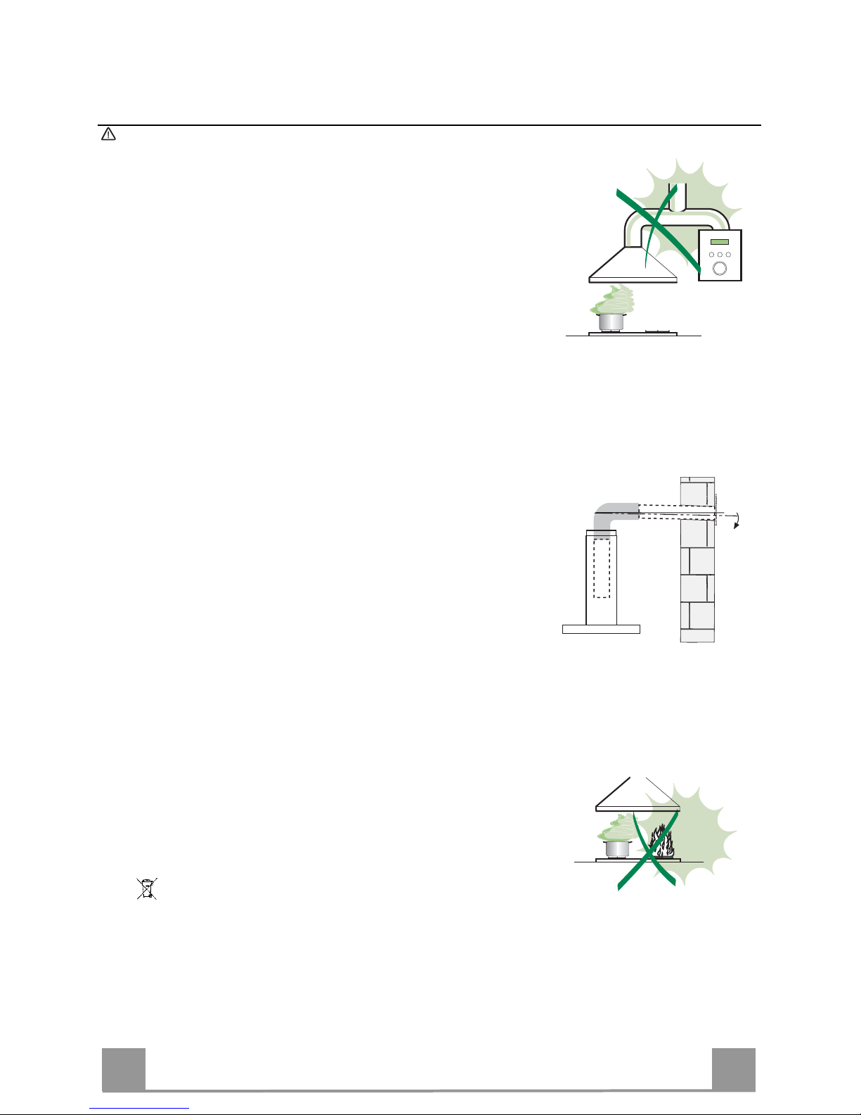
• The minimum safety distance between the cooker top and the extractor hood is 650 mm (some
models can be installed at a lower height, please refer to the paragraphs on working dimensions
and installation).
• Check that the mains voltage corresponds to that indicated on the rating plate fixed to the inside of
the hood.
• For Class I appliances, check that the domestic power supply guarantees adequate earthing.
Connect the extractor to the exhaust flue through a pipe of minimum diameter 120 mm. The route
of the flue must be as short as possible.
• Do not connect the extractor hood to exhaust ducts carrying combustion fumes (boilers, fireplaces,
etc.).
• If the extractor is used in conjunction with non-electrical appliances (e.g. gas burning appliances), a
sufficient degree of aeration must be guaranteed in the room in order to prevent the backflow of
exhaust gas. The kitchen must have an opening communicating directly with the open air in order
to guarantee the entry of clean air. When the cooker hood is used in conjunction with appliances
supplied with energy other than electric, the negative pressure in the room must not exceed 0,04
mbar to prevent fumes being drawn back into the room by the cooker hood.
• In the event of damage to the power cable, it must be replaced by the manufacturer or by the
technical service department, in order to prevent any risks.
• If the instructions for installation for the gas hob specify a greater distance specified above, this has
to be taken into account. Regulations concerning the discharge of air have to be fulfilled.
USE
• The extractor hood has been designed exclusively for domestic use to eliminate kitchen smells.
• Never use the hood for purposes other than for which it has been designed.
• Never leave high naked flames under the hood when it is in operation.
• Adjust the flame intensity to direct it onto the bottom of the pan only, making sure that it does not
engulf the sides.
• Deep fat fryers must be continuously monitored during use: overheated oil can burst into flames.
• Do not flambè under the range hood; risk of fire
• This appliance is not intended for use by persons (including children) with reduced physical, sensory or mental capabilities, or lack of experience and knowledge, unless they have been given supervision or instruction concerning use of the appliance by a person responsible for their safety.
• Children should be supervised to ensure that they do not play with the appliance.
• “ CAUTION: Accessible parts may become hot when used with cooking appliances.”.
MAINTENANCE
• Switch off or unplug the appliance from the mains supply before carrying out any maintenance
work.
• Clean and/or replace the Filters after the specified time period (Fire hazard).
• Clean the hood using a damp cloth and a neutral liquid detergent.
The symbol on the product or on its packaging indicates that this product may not be treated as household waste. Instead it shall be handed over to the
applicable collection point f or the recycling of electrical and electronic equipment. By ensuring this product is di sposed of correctly, you will help prevent pote ntial negative
consequences for the environme nt and human health, which could otherwi se be caused by inappropriate waste handling of this product. For more detailed information
about recycling of this pr oduct, please contact your local city office, your household wa ste disposal service or the shop where you purchased the prod uct
.
2°
EN
4
4
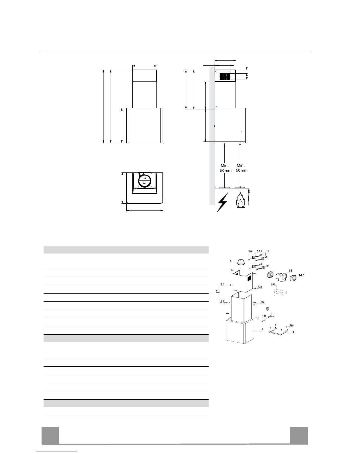
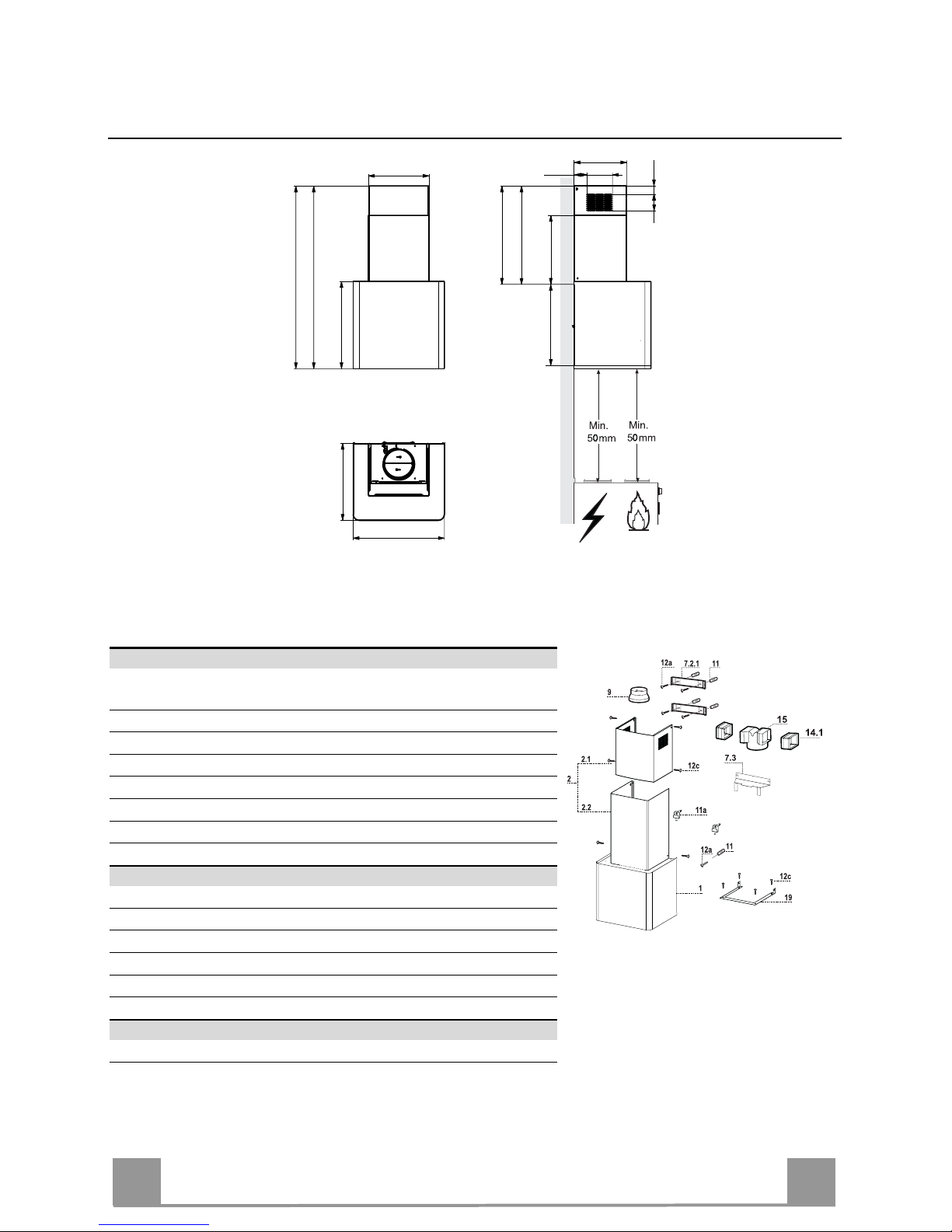
CHARACTERISTICS
450
380
430
126
81
41.5
300
260
62.5
340
* * MIN 460 - MAX 660
* MIN 340 - MAX 660
400
* * MIN 875 - MAX 1075
* MIN 755 - MAX 1075
6
6
* Dimensions of the hood in ducting version.
** Dimensions of the hood in recycling version.
Components
Ref. Q.ty Product Components
1 1 Hood Canopy, complete with: Controls, Light, Fan unit,
Filters
2 1 Telescopic chimney, comprising:
2.1 1 Upper chimney
2.2 1 Lower chimney
9 1 Reduction flange ø 150-120 mm
14.1 2 Air Outlet Connector Extension
15 1 Air Outlet Connector
19 1 Chimney Fixing Element
Ref. Q.ty Components for Installation
7.2.1 2 Upper Chimney Fixing Brackets
7.3 1 Connector Support Bracket
11 5 Plugs
11a 2 Plugs SB 12/10
12a 5 Screws 4.2 x 44.4
12c 10 Screws 2.9 x 6.5
Q.ty Documentation
1 Instruction Manual
EN
5
5
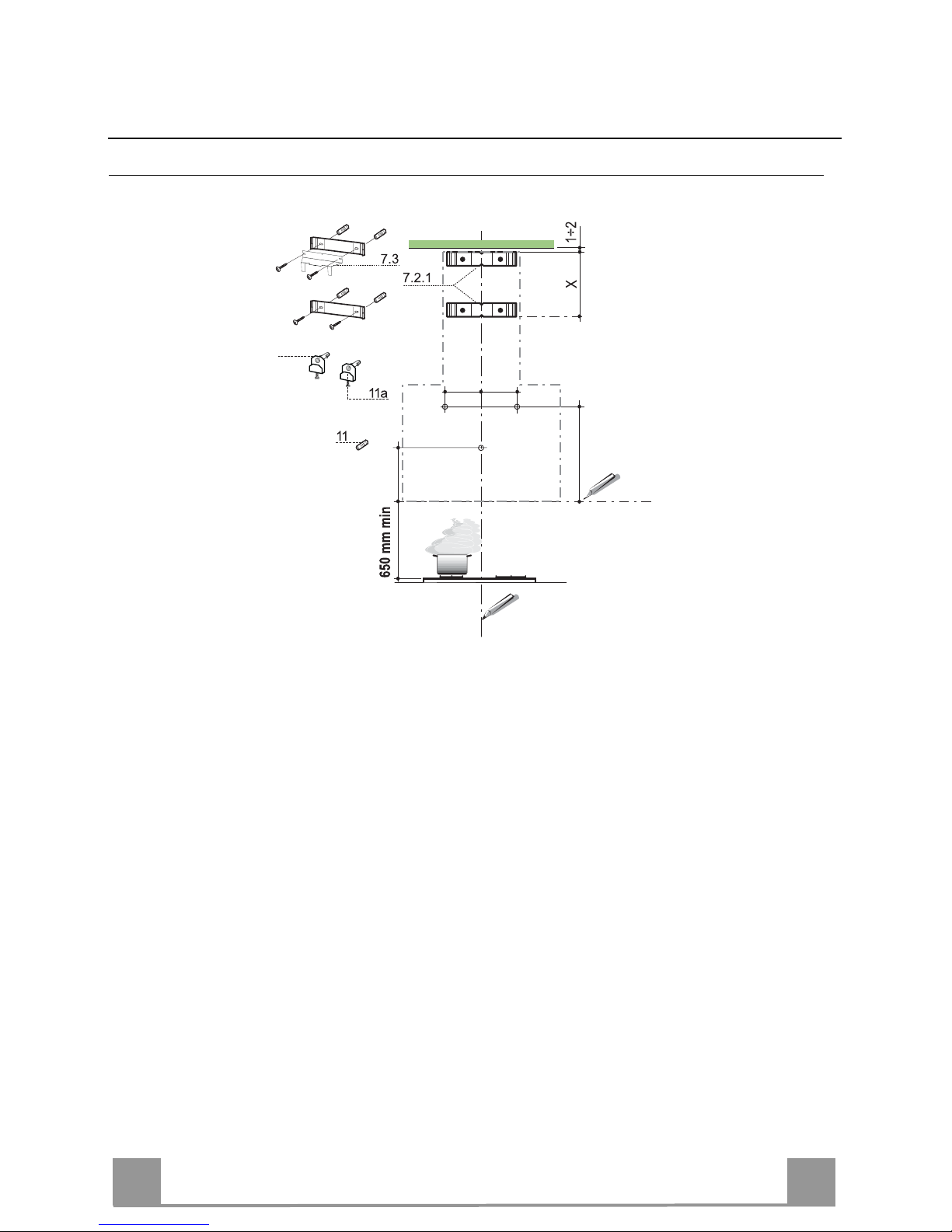
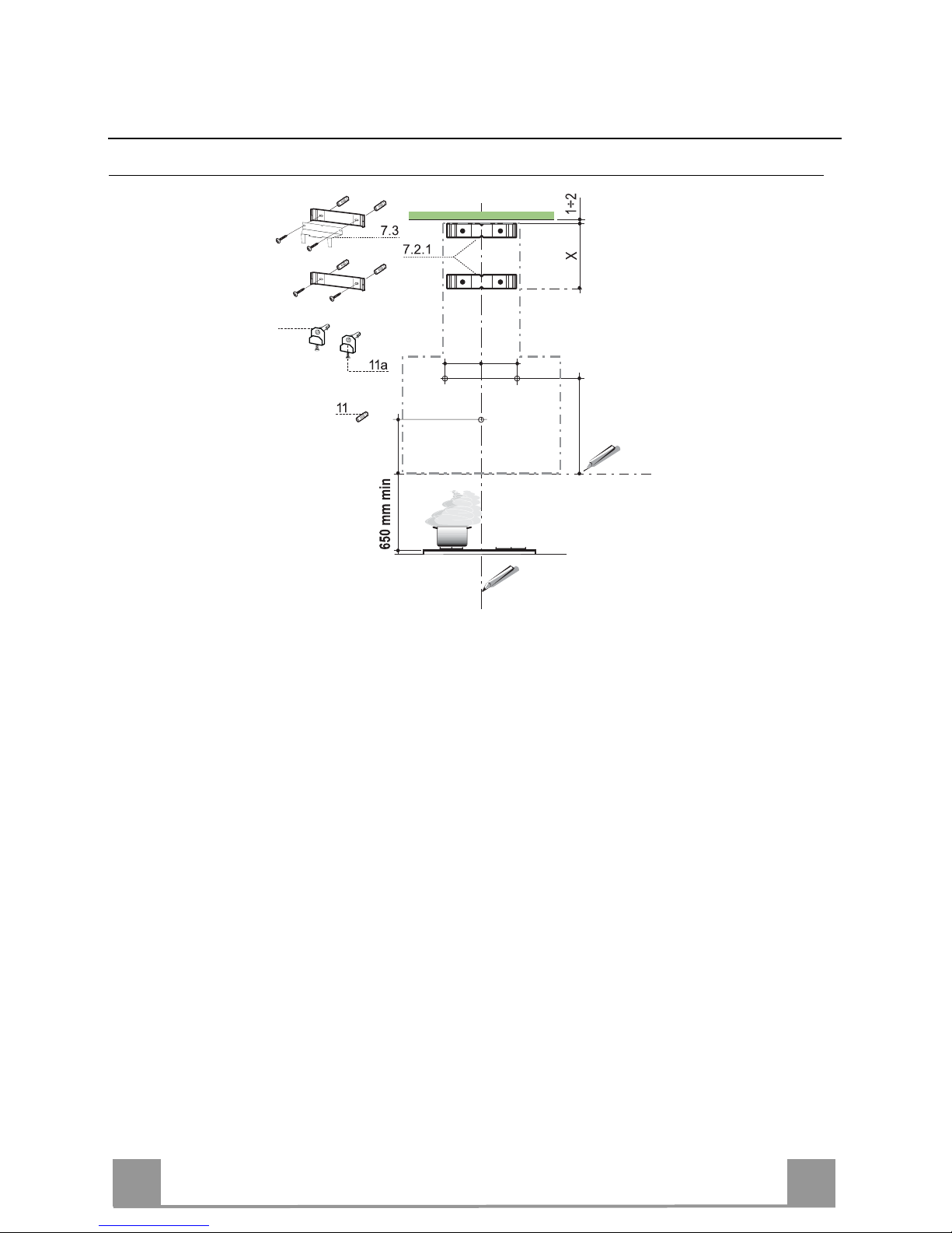
INSTALLATION
Drilling the Wall
373
105
150 150
12a
Mark the following on the wall:
• a vertical line up to the ceiling or surface above the hood, at the centre of the area in which
the hood itself is to be fitted;
• a horizontal line at: 650 mm min. above the Hob;
• Rest the Bracket 7.2.1 as indicated, 1-2 mm from the ceiling or surface above the hood,
aligning its centre (grooves) with the vertical reference line.
• Mark the centres of the holes in the bracket.
• Rest the Bracket 7.2.1 as indicated, X mm under the first bracket (X = height of the Upper
chimney provided), aligning its centre (grooves) with the vertical reference line.
• Mark the centres of the holes in the bracket.
• Mark a reference point as indicated at 105 mm from the horizontal reference line.
• Drill the points marked using an ø 8 mm bit.
• Insert the plugs 11 into the holes.
• Fix the Brackets, using the screws 12a (4.2 x 44.4) provided, and, only when fitting the
Hood in recirculation version with chimney, also fit the support bracket 7.3.
• As indicated above, mark a reference point 373 mm above the horizontal reference line, and
150 mm to the right of the vertical reference line.
• Repeat this operation on the opposite side, checking to ensure it is level.
• Drill the points marked using an ø 12 mm bit.
• Insert the plugs, screws and bracket 11a into the holes, and fasten.

EN
6
6
Mounting the hood body
• Remove the metal grease filters by turning the handles provided.
• Adjust the two screws Vr, on brackets 11a, to a minimum.
• Hook the hood canopy onto the two brackets 11a.
• From inside the hood canopy, adjust the screws Vr to set
the Hood Canopy level.
• Tighten the safety screws 12a.
Connections
DUCTED VERSION AIR EXHAUST SYSTEM
When installing the ducted version, connect the hood to the
chimney using either a flexible or rigid pipe ø 150 or 120
mm, the choice of which is left to the installer.
• To install a ø 120 mm air exhaust connection, insert the
reducer flange 9 on the hood body outlet.
• Fix the pipe in position using sufficient pipe clamps (not
supplied).
• Remove possible charcoal filters.
ø 150
9
ø 120
RECIRCULATION VERSION AIR OUTLET
• Insert the connection extension pieces laterally 14.1 in
connection 15.
• Insert the Connector 15 into the Support bracket 7.3 and fix
it with a screw.
• Make sure that the outlet of the extension pieces 14.1 is
horizontally and vertically aligned with the chimney outlets.
• Connect the air outlet connection 15 to the hood body outlet using either a flexible or rigid pipe ø 150 mm, the
choice of which is left to the installer.
• Ensure that the activated charcoal filters have been inserted.
15
ø 150
14.1
7.3
EN
7
7
ELECTRICAL CONNECTION
• Connect the hood to the mains through a two-pole switch
having a contact gap of at least 3 mm.
• Remove the grease filters (see paragraph Maintenance) being sure that the connector of the feeding cable is correctly
inserted in the socket placed on the side of the fan.
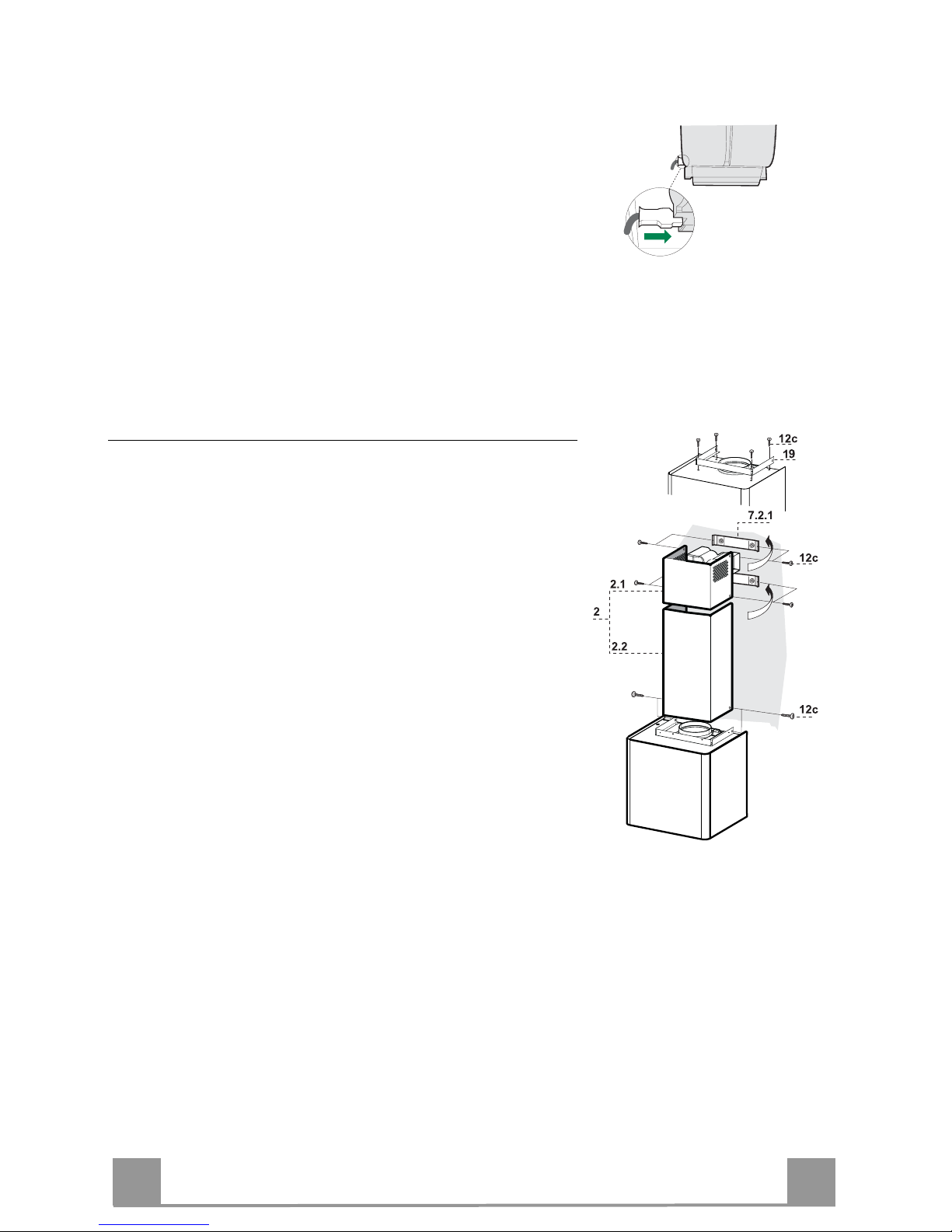
Chimney Assembly
• Fasten the Chimney fixing element 19 to the Body using 4
screws 12c.
Upper chimney
• Open the two side pieces out slightly, hook them up behind
the brackets 7.2.1 and bring them back together again until
they are in contact.
• Fix to the Brackets at the sides, using 4 screws 12c (2.9 x
9.5) provided.
• If there are any, make sure that the Connector extensions
outlet is in correspondence with the Chimney openings.
Lower chimney
• Open the two side pieces of the Chimney out slightly, hook
them between the upper chimney and the wall, and then
close them together again until they are in contact.
• Fix the part at the sides to the Chimney fixing element 19,
using 2 screws 12c (2.9 x 9.5) provided.
EN
8
8
USE
T2
T1
L
T3
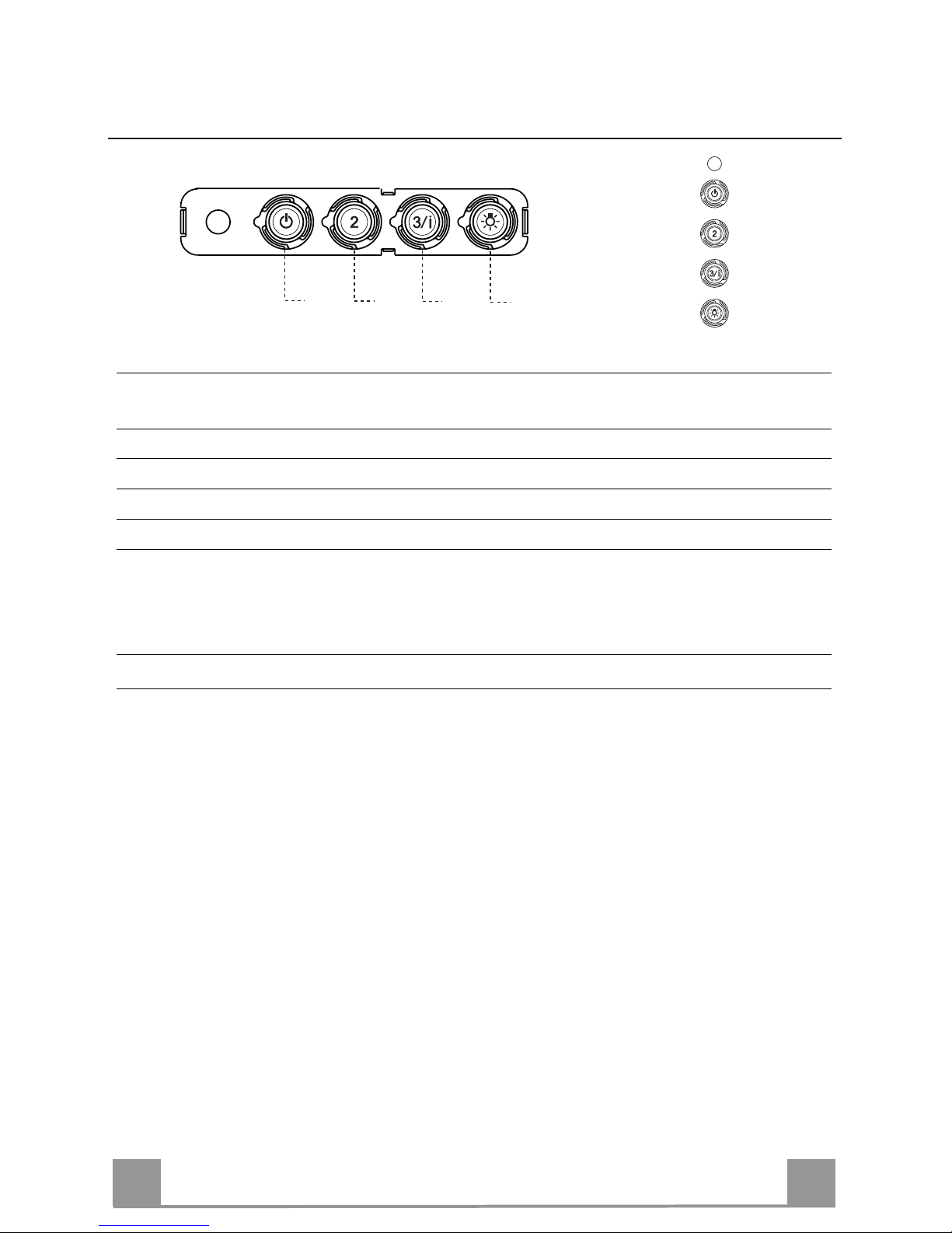
Control panel
BUTTON LED FUNCTIONS
T1 Speed On Turns the Motor on at Speed one.
Turns the Motor off.
T2 Speed On Turns the Motor on at Speed two.
T3 Speed Fixed When pressed briefly, turns the Motor on at Speed three.
Flashing Pressed for 2 Seconds.
Activates Speed four with a timer set to 10 minutes, after
which it returns to the speed that was set previously. Suitable
to deal with maximum levels of cooking fumes.
L Light Turns the Lighting System on and off.
Warning: Button T1 turns the motor off, after first passing to speed one.

EN
9
9
MAINTENANCE
Grease filters
CLEANING METAL SELF- SUPPORTING GREASE FILTERS
• The filters must be cleaned every 2 months of operation, or
more frequently for particularly heavy usage, and can be
washed in a dishwasher.
• Remove the filters one at a time by pushing them towards the
back of the group and pulling down at the same time.
• Wash the filters, taking care not to bend them. Allow them to
dry before refitting.
• When refitting the filters, make sure that the handle is visible
on the outside.
Activated charcoal filter (Recirculation version)
These filters are not washable and cannot be regenerated, and
must be replaced approximately every 4 months of operation, or
more frequently with heavy usage.
REPLACING THE ACTIVATED CHARCOAL FILTER
• Remove the metal grease filters
• Remove the saturated activated charcoal filter as shown (A).
• Fit the new filters (B).
• Replace the metal grease filters.
A
B
Lighting
LIGHT REPLACEMENT
20 W halogen light.
• Extract the lamp from the lamp holder by pulling gently.
• Replace with another of the same type, making sure that the
two pins are properly inserted in the lamp holder socket holes.

SE
1
10
REKOMMENDATIONER OCH TIPS
Denna bruksanvisning är förutsedd för flera versioner av apparaten.
Det är möjligt att vissa enskilda utrustningsdetaljer, inte berör din apparat.
INSTALLATION
• Tillverkaren åtar sig inget ansvar för fel som beror på felaktig eller olämplig installation.
• Minsta tillåtna avstånd mellan spishäll och köksfläkt är 650 mm (vissa modeller kan installeras på en lägre
höjd, se avsnitten mått och installation).
• Kontrollera att matningsnätets spänning motsvarar den som anges på märkskylten inuti köksfläkten.
• För Klass I-apparater, kontrollera att matningsnätet ger effektiv jordning.
• Anslut fläkten till frånluftkanalen via ett rör med en diameter på minst 120 mm. Anslutningsröret skall hållas
så kort som möjligt.
• Anslut inte köksfläkten till frånluftkanaler som leder förbränningsgaser (från pannor, eldstäder etc.).
• Om fläkten används tillsammans med icke-elektriska spisar (t.ex. gasspisar) måste tillräcklig ventilation
garanteras i lokalen för att förhindra backflöde av förbränningsgaser. Köket måste ha ett tilluftdon med direkt
anslutning mot ytterluft för att garantera inflöde av friskluft. Korrekt är riskfri användning säkerställas när det
maximala undertryck i lokalen inte överstiger 0,04 mbar
• I händelse av skada på kabeln, måste den bytas av tillverkaren eller av den tekniska serviceavdelning, för
att undvika risker.
• Om installationsanvisningarna för matlagningsanordningen med gas anger att ett större avstånd än det
ovan angivna är nödvändigt måste det beaktas. Man måste följa alla regler om luftutsläpp.
ANVÄNDNING
• Köksfläkten är uteslutande avsedd för hemanvändning, för att eliminera köksos.
• Använd aldrig köksfläkten för andra ändamål än det avsedda.
• Undvik höga flammor under köksfläkten medan fläkten är i drift.
• Justera gaslågan så att flammorna endast berör kokkärlets undersida och inte tränger upp längs dess
sidor.
• Fritöser måste övervakas kontinuerligt under användning: Överhettad olja kan fatta eld.
• Köksfläkten skall inte användas av barn eller personer som inte är insatta i korrekt användning.
• Apparaten är inte avsedd att användas av barn eller handikappade personer utan övervakning.
• Tillaga inga flamberade maträtter under köksfläkten, då det finns risk för eldsvåda
• Denna apparat får inte användas av personer (inklusive barn) med nedsatta fysiska, sensoriska eller mentala förmågor, eller av personer utan erfarenhet och kunskap, om inte de är kontrollerade eller instruerade
om användningen av apparaten av personer ansvariga för deras säkerhet.
• Barn ska övervakas för att säkerställa att de inte leker med apparaten.
• “VARNING: De åtkomliga delarna kan bli mycket varma om de används med matlagningsapparater.”.
UNDERHÅLL
• Stäng av apparaten eller skilj den från matningsnätet innan något underhållsarbete utförs.
• Rengör och/eller byt filtren med angivet intervall (Risk för eldsvåda).
• Rengör köksfläkten med en fuktig trasa och neutralt flytande diskmedel.
Symbolen på produkten eller emballaget anger att produkten inte får hanteras som hushållsavfall. Den skall i stället lämnas in på uppsamlingsplats för återvinning av el- och elektronikkomponenter. Genom att säkerställa att produkten hanteras på rätt sätt bidrar du till att förebygga eventuellt
negativa miljö- och hälsoeffekter som kan uppstå om produkten kasseras som vanligt avfall. För
ytterligare upplysningar om återvinning bör du kontakta lokala myndigheter eller sophämtningstjänst
eller affären där du köpte varan.
2°
SE
1
11
EGENSKAPER
450
380
430
126
81
41.5
300
260
62.5
340
* * MIN 460 - MAX 660
* MIN 340 - MAX 660
400
* * MIN 875 - MAX 1075
* MIN 755 - MAX 1075
6
6
* Mått för köksfläkt i sugande version.
** Mått för köksfläkt i filtrerande version.
Komponenter
Ref. Antal Produktkomponenter
1 1 Köksfläktsstomme komplett med: Reglage, Belysning,
Fläktenhet, Filter
2 1 Teleskopisk skorsten bestående av:
2.1 1 Övre skorsten
2.2 1 Undre skorsten
9 1 Reduktionsfläns ø 150-120 mm
14.1 2 Förlängt anslutningsstycke för luftutsläpp
15 1 Anslutningsstycke för luftutsläpp
19 1 Skorstenens fästvinkel
Ref. Antal Installationskomponenter
7.2.1 2 Konsoler för fastsättning av övre skorsten
7.3 1 Stödkonsol för anslutningstycke
11 4 Expansionspluggar
11a 2 Expansionspluggar SB 12/10
12a 4 Skruvar 4,2 x 44,4
12c 10 Skruvar 2,9 x 6,5
Antal Dokumentation
1 Bruksanvisning
SE
1
12
INSTALLATION
Borrning i vägg
373
105
150 150
12a
Markera på väggen:
• ett vertikalt streck upp till taket eller max. gränsen, i mitten av köksfläktens monteringsområde;
• ett horisontellt streck till: 650 mm min. ovanför tillagningshällen;
• Placera konsolen 7.2.1 1-2 mm från taket eller den övre gränsen. Ställ in konsolens mitt
(hack) på det vertikala referensstrecket.
• Markera konsolens hål.
• Placera konsolen 7.2.1 X mm under den första konsolen (X = höjd för medföljande övre
skorsten) enligt anvisningarna. Ställ in konsolens mitt (hack) på det vertikala
referensstrecket.
• Markera konsolens hål.
• Markera en referenspunkt vid 105 mm från det horisontala referensstrecket.
• Borra ø 8 mm hål i de markerade punkterna.
• Sätt i expansionspluggarna 11 i hålen.
• Fäst konsolerna med de medföljande skruvarna 12a (4,2 x 44,4), och enbart ifall av
köksfläkt i filtrerande version med skorsten, fäst även stödkonsolen 7.3.
• Markera som angivet, en referenspunkt vid 373 mm över den horisontella referenslinjen, och
vid 150 mm till höger om den vertikala referenslinjen.
• Upprepa detta moment från den motsatta sidan, kontrollera nivelleringen.
• Borra ø 12 mm hål i de markerade punkterna.
• Sätt i expansionspluggarna med skruvar och konsolen 11a i hålen, skruva fast.
 Loading...