

Page 1
Page 2

INTRODUCTION
Thank you for having chosen our LED lighting
Unpack the device, inside the box you should find:
The fixture device
One power cable
One XLR connection cable
This manual
Please check carefully that there is no damage caused by
transportation. Should there be any problems, consult your dealer and
don’t install this device.
DESCRIPTION
Features
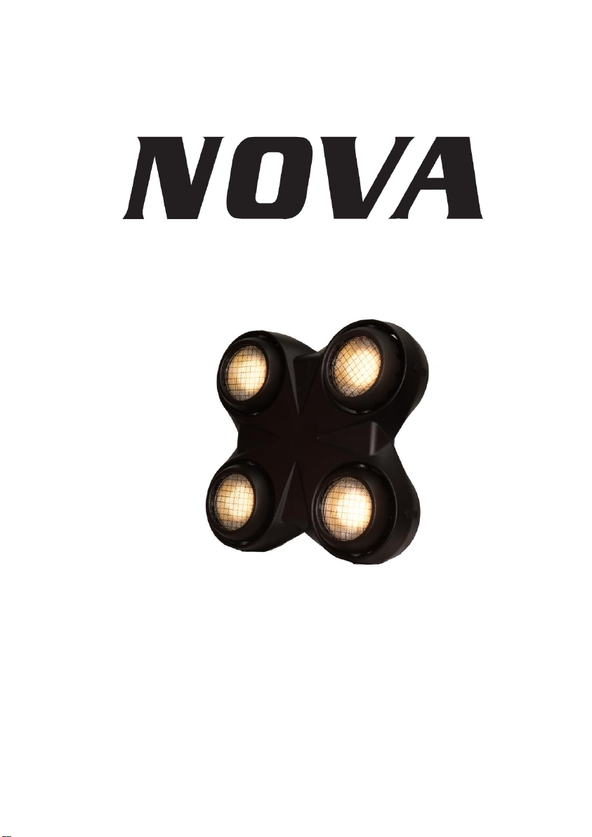
Easy multi fixture hanging system, outdoor version available
4*100w 3000k LED, no ultraviolet radiation
More than 50,000 hours for the LED light source life
1300 lux in 5 meters
60 degree for beam angle
1/3/4/9 DMX channels
16 Bit Dimmer
DMX Mode /Master-slave mode
AC 100-240V 50/60Hz 400W
Diecasting heatsink, convection cooling, auto fans speed, no noise
With temperature sensor to extend the lamp life
7000 Hz LED scan rate
L: 373mm H:373mm W:193mm, Weight 9Kg
IP65/IP43 can be chosen
SAFETY INSTRUCTIONS
This device has left the factory in perfect condition. In order to
maintain this condition and to ensure a safe operation, it
is absolutely necessary for the user to follow the safety
instructions and warning notes written in this user manual.
This device falls under protection-class I. Therefore it is essential that
the device should be earthed.
The electric connection must carry out by qualified person.
1
Page 3

Never look directly into the light source, as
sensitive persons may suffer an epileptic shock.
If the external flexible cable or cord of this luminaire is damaged,
it shall be exclusively replaced by the manufacturer or his
service agent or a similar qualified person in order to avoid a hazard.
Make sure that the available voltage is not higher than stated at the
end of this manual.
Make sure the power cord is never crimped or damaged by sharp
edges.
If this would be the case, replacement of the cable must be done by
an authorized dealer.
Always disconnect from the mains, when the device is not in use or
before cleaning it. Only handle the power cord by the plug. Never
pull out the plug by tugging the power cord.
Important:
Damages caused by the disregard of this user manual are not
subject to warranty. The dealer will not accept liability for any
resulting defects or problems.
DMX-512 control connection
The product has a DMX 512 input fitted with 3-pin XLR connectors.
Screened cables in compliance with EIA RS-485 specifications and the
following characteristics must be used for connections:
- 2 conductors plus screen
- 120Ohm impedance
- low capacitance
- max. transmission rate 250kBaud.
DMX-512 connection with DMX terminator
For installations where the DMX cable has to run a long distance or is
in an electrically noisy environment,such as in a discotheque, it is
recommended to use a DMX terminator. This helps in preventing
corruption of the digital control signal by electrical noise. The DMX
2
Page 4
Main menu
Sub-menu
Value
Default
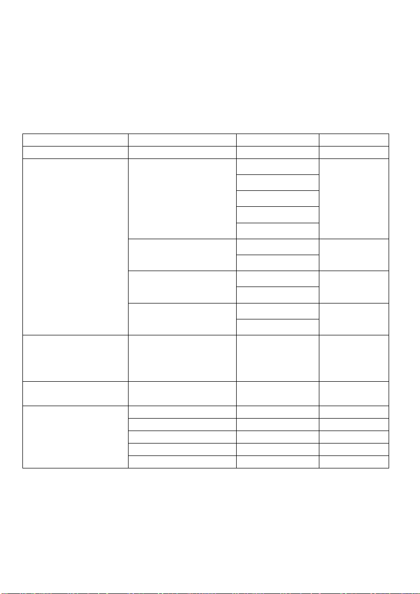
DMX Address
DMX Address Setting
1 - 512
1
Configure
Channel Mode
Channel 1Ch
Channel 9Ch
Channel 3Ch
Channel 4Ch
Channel 9Ch
Channel 10Ch
Keep Screen On
Disable
Disable
Enable
Keep Dmx Data
Disable
Disable
Enable
Fast Dimmer Mode
Enable
Enable
Disable
Information
Temperature
Temperature Of
Head 1 To Head
4
Auto Mode
-
Flowing Water
Light
-
Static Mode
Led Head 1
0 - 255
0
Led Head 2
0 - 255
0
Led Head 3
0 - 255
0
Led Head 4
0 - 255
0
Led Strobe
0 - 255
0
terminator is simply an XLR plug with a 120 OHM resistor connected
between pins 2 and 3,which is then plugged into the output XLR
socket of the last fixture in the chain.
Display Menu
Main functions
1. Address:Current DMX address
A.Setting DMX address by button
3
Page 5

Press ENTER button when show the address menu, then adjust
the DMX address by pressing [UP] or [DOWN] button.
Press [ENTER] to confirm or pressing [ESC] to return to main
menu.
B.Setting DMX address by controller
1.Set the DMX value of channel 5 to 10-15,channel 17 to 20-26,
channel 7 to 30-36,channel 8 to 40-46,then the devices
connected to the controller will enter to the setting address mode
2. Set the DMX value of channel 1 from 0-59,then you will see
the the first number of the Address change to (channel 1
vaule)/10.
For example,when set the value of channel 1 to 20,the first DMX
address number will be 2(20/10=2).
3. Set the DMX value of channel 2 from 0-99,then you will see
the the sencond number of the Address change to (channel 2
vaule)/10.
For example,when set the value of channel 2 to 30,the first DMX
address number will be 3(30/10=3).
4.Set the DMX value of channel 3 from 0-99,then you will see the
the third number of the Address change to (channel 3 vaule)/10.
For example,when set the value of channel 1 to 40,the first DMX
address number will be 4(40/10=4).
And the DMX address you set by conctroller will be 234.
5. Set the DMX value of channel 4 to 255,then you will save the
DMX address setted by the controller.
Caution: It won’t save the address if the address number is
over 512.
6. Set the value of channel 5-8 out of the value range show on the
step 1,and the device will exit the setting address mode.
2. Configure
Setting channel mode
Select the channel mode by pressing [UP] or [DOWN] button.
Keep screen on
Select the enable/disable by pressing [UP] or [DOWN] button.
Setting this to disable will close the screen automaticly as soon
as NO operation to keyboard in 45 seconds.
4
Page 6

Setting this to enable will keep the screen on.
Keep DMX data
Select enable/disable by pressing [UP] or [DOWN] button.
Setting this to enable will set all DMX channel level to 0 as soon
as DMX signal lost.
Setting Fast mode
Select enable/disable by pressing [UP] or [DOWN] button.
Setting this to enable, the LEDs brightness will be set to
maximum or minimum immediate without delay effect as soon
as you change DMX level from the lowest to the highest or the
highest to the lowest in fast-speed.
3. Information
Temperature
Press [ENTER] button when show the Temperature menu, then
it will show the temperatures of 4 LED heads.
4. Auto Mode
Press [ENTER] button to enter Auto Mode menu, press [ENTER]
button to select the color mode, then select auto run mode by
pressing [UP] or [DOWN] button.
5. Static Mode
Press [ENTER] button to enter Static Mode, press [UP] or
[DOWN] button to select the Led head or strobe, then [ENTER] ,
adjust the value by pressing [UP] or [DOWN] button.
In this mode, DMX input is INVALID. Leds brightness and strobe
effect are controlled by this menu.
DMX functions and values
1CH Mode
5
Page 7
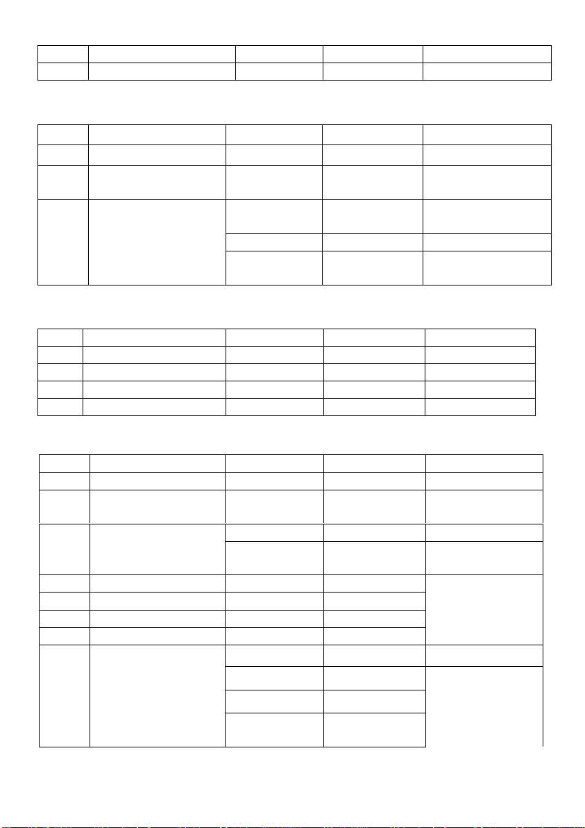
No.
Function
Value
Description
Remark
1
Master Dimmer
000-255
0-100%
-
No.
Function
Value
Description
Remark
1
Master dimmer
000-255
0-100%
-
2
Fine
master dimmer
000-255
0-100%
-
3
Strobe
000-015
Unused
range
-
016-240
Strobe
From slow to fast
241-255
Random
strobe
From fast to slow
No.
Function
Value
Description
Remark
1
LED Head 1
000-255
0-100%
-
2
LED Head 2
000-255
0-100%
-
3
LED Head 3
000-255
0-100%
-
4
LED Head 4
000-255
0-100%
-
No.
Function
Value
Description
Remark
1
Master Dimmer
000-255
0-100%
-
2
Fine
Master Dimmer
000-255
0-100%
-
3
Strobe
000-015
Unused range
-
016-255
Strobe
From slow to
fast 4 LED Head 1
000-255
0-100%
-
5
LED Head 2
000-255
0-100%
6
LED Head 3
000-255
0-100%
7
LED Head 4
000-255
0-100%
8
Macro
000-035
Unused range
036-071
Ramp up
From fast to
slow
072-107
Ramp down
108-143
Ramp up
and-down
3CH Mode
4CH Mode
9CH Mode
6
Page 8
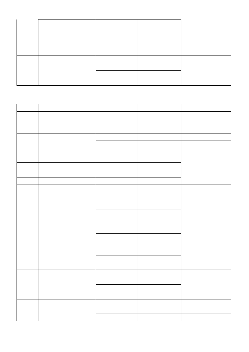
144-179
Ramp up by
SIN curve
180-215
4-LED flow
216-255
Random LED
on
9
Dimmer Curve
0-63
Linear
-
64-127
Square
128-191
Invert Square
192-255
S-Surve
No.
Function
Value
Description
Remark
1
Master Dimmer
000-255
0-100%
-
2
Fine
Master Dimmer
000-255
0-100%
-
3
Strobe
000-015
Unused range
-
016-255
Strobe
From slow to
fast 4 LED Head 1
000-255
0-100%
-
5
LED Head 2
000-255
0-100%
6
LED Head 3
000-255
0-100%
7
LED Head 4
000-255
0-100%
8
Auto Mode
000-035
Unused
range
From fast to
slow
036-071
Ramp up
072-107
Ramp down
108-143
Ramp up
and-down
144-179
Ramp up by
SIN curve
180-215
4-LED flow
216-255
Random LED
on
9
Dimmer Curve
0-63
Linear
-
64-127
Square
128-191
Invert Square
192-255
S-Curve
10
Dimmer Speed
0-254
Normal speed
From fast to
slow
255
Tungsten
-
10CH Mode
7
Page 9
effect
CAUTION!Disconnect from mains before starting
maintenance operation.
CLEANING AND MAINTENANCE
We recommend a frequent cleaning of the device. Please use a soft
lint-free and moistened cloth. Never use alcohol or solvents!
There are no servicable parts inside the device. Maintenance and
service operations are only to be carried out by authorized dealers.
If you need any spare parts, please use genuine parts.
If the power supply cable of this device becomes damaged, it has to
be replaced by authorized dealers only in order to avoid hazards.
If you have further questions, please contact your dealer.
INSTALLATION
The device must only be installed at a vibration-free, oscilation-free
and fire-resistant location.
8
 Loading...