

TourPro Lighting ExtremeBeam 230 User Manual
Please read these user manual carefully before use
USER MANUAL
EXTREME SERIES
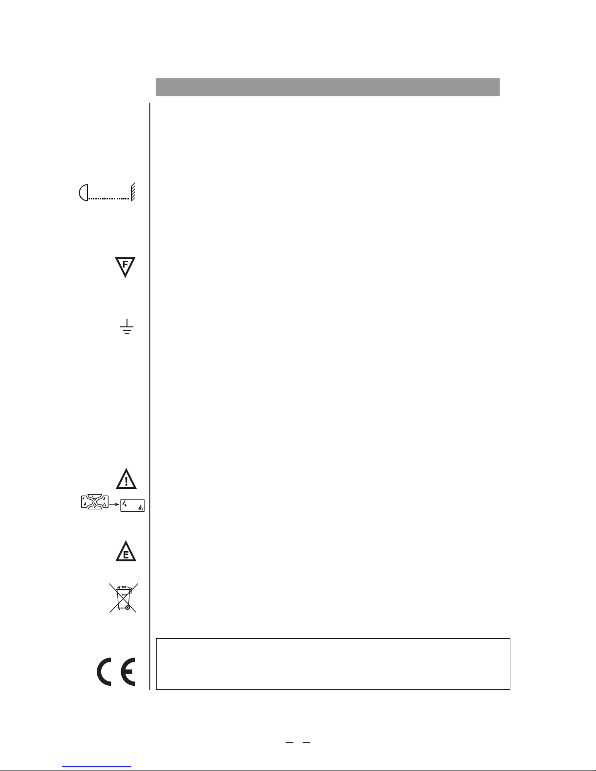
Minimum di stanc e to flam mable m ateri al=12 m.
Minimum di stanc e to illu minat ed surf ace=
Maximum am bient t emper ature t =33℃.
a
Always dis conne ct from m ains be fore re placi ng
the lamp.
Caution: Hot lam p. Allow t o cool fo r 30 minu tes
before ope ning.
Exterior s urfac e tempe ratur e under s teady
state cond ition = 45 .
Prolonge d expos ure to un shiel ded
lamp can cau se eye an d skin bu rns.
℃
12m
WARNI NG:HO T!
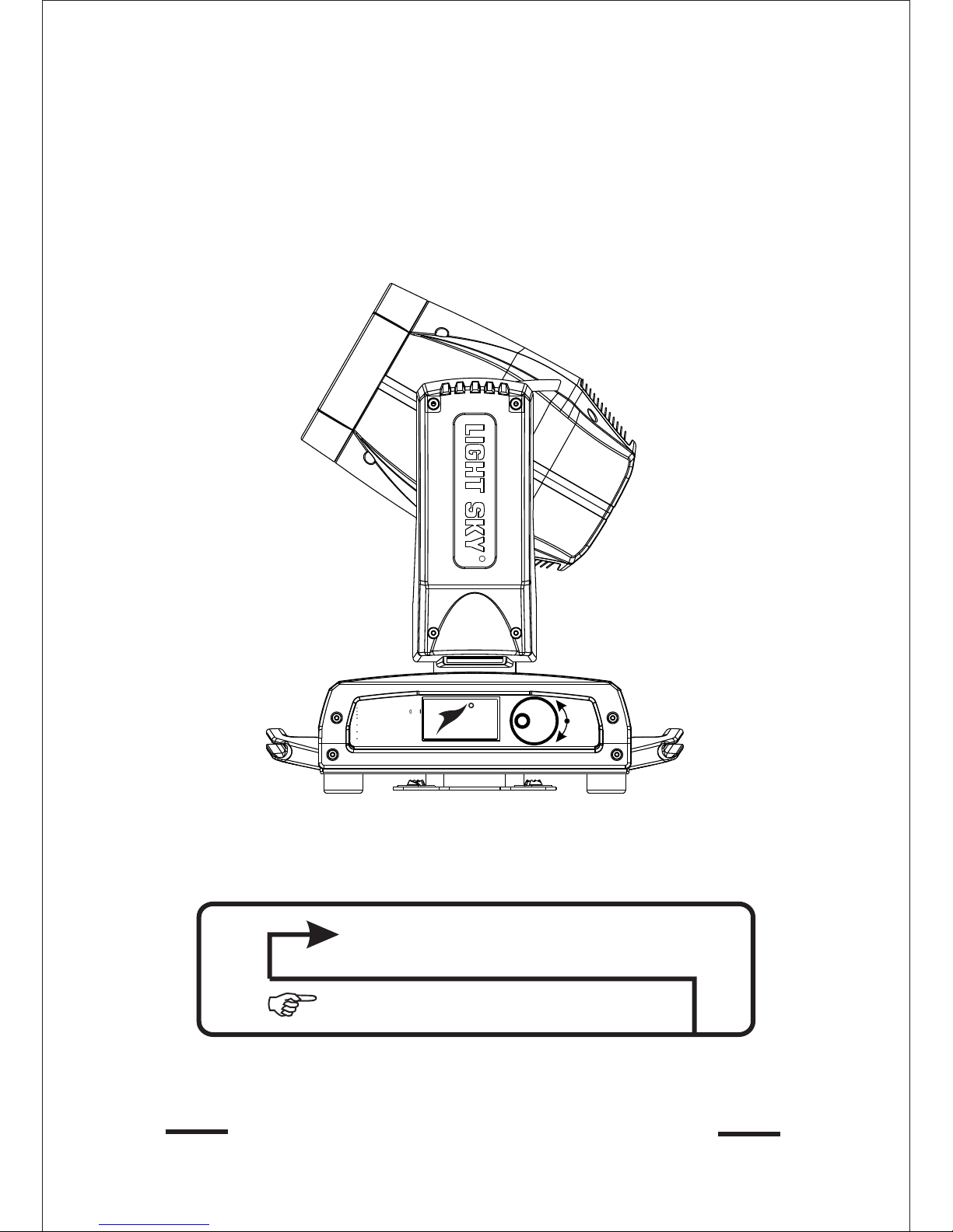
ENTER
UP
DOWN
LIGHT SKY
R
R
ExtremeBeam 230
TourPro
Lighting
www.tourprolighting.com

www.tourprolighting.com
Congratu lati ons on choosing our company product! We thank you for your custom.
◆Please note that this product, as all the others in the ric h my company range, has
been designed and made with total quality to ensure excellent per formance and
best meet your expectations and requirements.
◆
Car
efully read this user manual in its entirety and keep it safe for future reference.
It is essential to know the information and comply with t he instructions given in this
manual to ensure the fitting is installed, used and serviced correctly and safely.
◆My co
mpany disclaims all liability for damage to the fitting or to other property or
persons deriving from installation, use and maintenance that have not been carried
out in conformity with this user manual, which must alw ays accompany the fitting.
◆
My co
mpany reserves the right to modify the characterist ics stated in this user
manual at any time and without prior notice.
Contents
1
. Safe
ty information....................................................................................................2
2.Technical information...............................................................................................3
3.Attachment ........................................................................................4
4.Installation and connecting.......................................................................................5
5. Control panel............................................................................................................6
6. Menu setting.............................................................................................................8
7.Channel function.....................................................................................................12
8. .....................................................................................17
9. ................................. ................................... .................18
10. .... .. ................................................. .. ...........................................18
11. ...........................................................19
12. Company information...........................................................................................20
and body size
Circuit connecting diagram
Duty exonerative and copyright protection
Cleaning and maintenances
Tro ubeshooting
1
www.tourprolighting.com
• Installation
Make sure all parts for fixing the projector are in a good state of repair.
Make sure the point of anchorage is stable before positioning the projector.
The safety chain must be properly hooked onto the fitting and secured to the framework, so that,
if the primary support system fails,the fitting falls as little as possible.
If the safety chain gets used, it needs to be replaced with a genuine spare.
• MINIMUM DISTANCE OF ILLUM INATED OBJECTS
The projector needs to be positioned so that the objects hit by the beam of light are at least
12 metres from the lens of the projector.
• Minimum distance from flammable materials
The projector must be posit
every point on the surface of the fitting.
Ioned so that any flammable materials are at least 0.2 metres from
• Mounting surfaces
It is permissible to mount the fitting on normally flammable surfaces.
• Maximum ambient temperature
Do not operate the fixt ℃ure if the ambient temperature (Ta) exceeds 33 .
•Protection against electrical shock
Connection must be made to a power supply system fitted with efficient earthing (Class I appliance
according to standard EN 60598-1).
It is,moreover, recommended to protect the supply lines of the projectors from indirect contact and/or
shorting to earth by using appropriately sized residual current devices.
• Connection to mains supply
Connection to the electricit
Check that the mains frequency and voltage correspond to those for which the projector is designed
as given on the electrical data label.
This label also gives the input power to which you need to refer to evaluate the maximum number
of fittings to connect to the electricity line, in order to avoid overloading.
y mains must be carried out by a qualified electrical installer.
• Temperature of the external surface
The maximum temperature that can be reached on the external surface of the fitting, in a thermally
steady state, is 45℃.
• Maintenance
Before starting any maintenance work or cleaning the projector, cut off power from the mains
After switching off, do not remove any parts of the fitting, to avoid getting burnt for at least 30 minutes.
After this time the likelihood of the lamp exploding is virtually nill.
The fitting is designed to hold in any splinters produced by a lamp exploding. The lenses must be
mounted and, if visibly Damaged, they have to be replaced with genuine spares.
supply.
• Lamp
The fit
apparatus.
-Carefully read the "operating instructions" provided by the lamp manufacturer.
-Immediately replace the lamp if damaged or deformed by heat.
ting mounts a high-pressure lamp that needs an external igniter. This igniter is fitted onto the
• Battery
This product contains a rechargeable lead-acid battery. To preserve the environment, please d
the battery at the end of its life according to the regulation in force.
ispose
SAFETY INFORMATION
The products referred to in this manual conform to the European Community Directives to which
they are subject:
•Low Voltage 2006/95/CE
•Electromagnetic Compatibility 2004/108/CE
Pb
12m
t 45℃
c
2
t 33℃
a
www.tourprolighting.com
3
Power supplies available
□110V □220V □100-240V 50/60Hz
Lamp:
- Brand:OSRAM,PHILIPS
- Lamp power: 230W,190W,189W,180W(Apolegamic)
- Colour temperature 8000K
- Average life 3000h
- Any working position
Motors:
13 stepper motors, operating with microsteps,
Totally Microprocessor controlled.
Channels:
Standard Max 20 control 16 control channels, channels.
Zoom:
0 3.8° °-
Inputs:
• DMX 512/WIRELESS DMX 512(Apolegamic)
Movable body:
•Movement by means of two stepper motors,
Controlled by microprocessor.
• Automatic repositioning of PAN and TILT after accidental
Movement not controlled by control Unit.
• Travel:
- PAN = 540°
- TILT = 250°
• Maximum speeds:
- PAN = 3.5S (normal)/ 2.7S (fast)
- TILT = 2.1S (normal)/ 1.6S (fast)
• Resolution:
- PAN = 2.11°
- PAN FINE = 0.008°
- TILT = 0.98°
- TILT FINE = 0.004°
IP20 protection rating:
• Protected against the entry of solid bodies larger than 12mm.
• No protection against the entry of liquids.
CE Marking:
In conformity with the European Union Low Voltage.
Directive 2006/95/CE and Electromagnetic compatibility
Directive 2004/108/CE.
Safety Devices:
• Bipolar circuit breaker with thermal protection.
• Automatic break in power supply in case of
overheating or failed operation of cooling system.
Cooling:
Forced ventilation with axial fans.
Body:
• Aluminium structure with die-cast plastic cover.
• Two side handles for transportation.
• Device locking PAN and TILT mechanisms for
transportation and maintenance.
Working position
Functioning in any position.
Weights and size
Box Size:
Flycase Size:
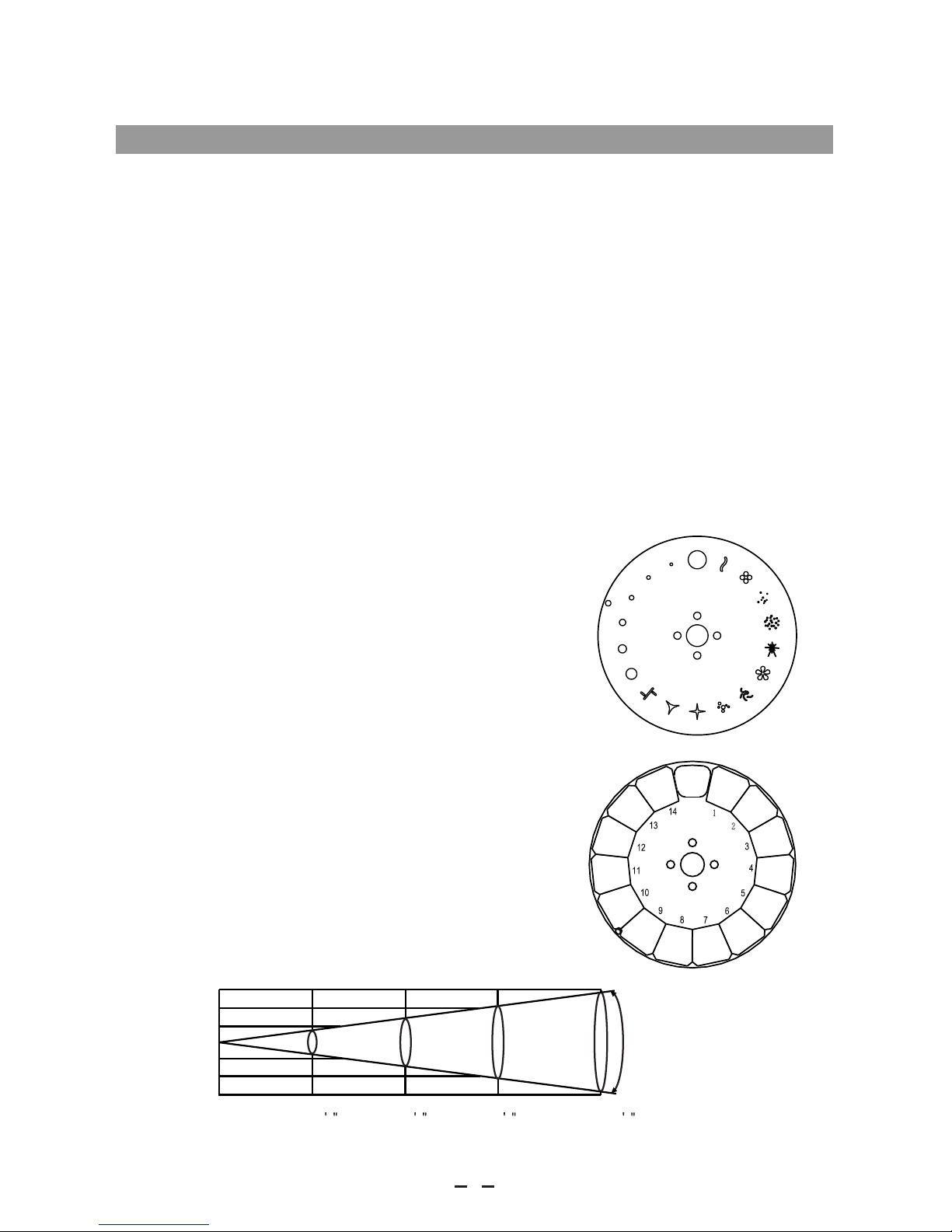
Gobo Wheel(please refer to the actual material):
Color Wheel:(please refer to the actual material):
N.W.:17.5kg G.W.:21.3kg
TECHNICAL INFORMATION
Photometric Data :
1
2
3
4
5
6
7
8
9
10
11
12
13
14
15
16
17
450x430x530(mm)
2PCS:790x650x680(mm) N.W.:35kg G.W.:76kg
4PCS:1025x810x680(mm) N.W.:70kg G.W.:135kg
Whi te
Dar k
red
Ora nge
Aqua marin e
Dee p
gre en
Dee p
Lav ender
Pin k
Yell ow
Mag enta
Cya n
Dar k
blu e
CTB
CTO 1
CTO 2
0
1
2
3
20m
1.46m( 4 8 ) 2.8m(9 2 ) 4.13m( 13 5 ) 5.46m( 17 9 )
0m
0m
40m
60m
80m
78680( 7312)
19670( 1828)
8742(8 12)
4918(4 57)
1
2
3
3. 8°
Lux(f c)
Distance m
Diameter m(ft in )
www.tourprolighting.com
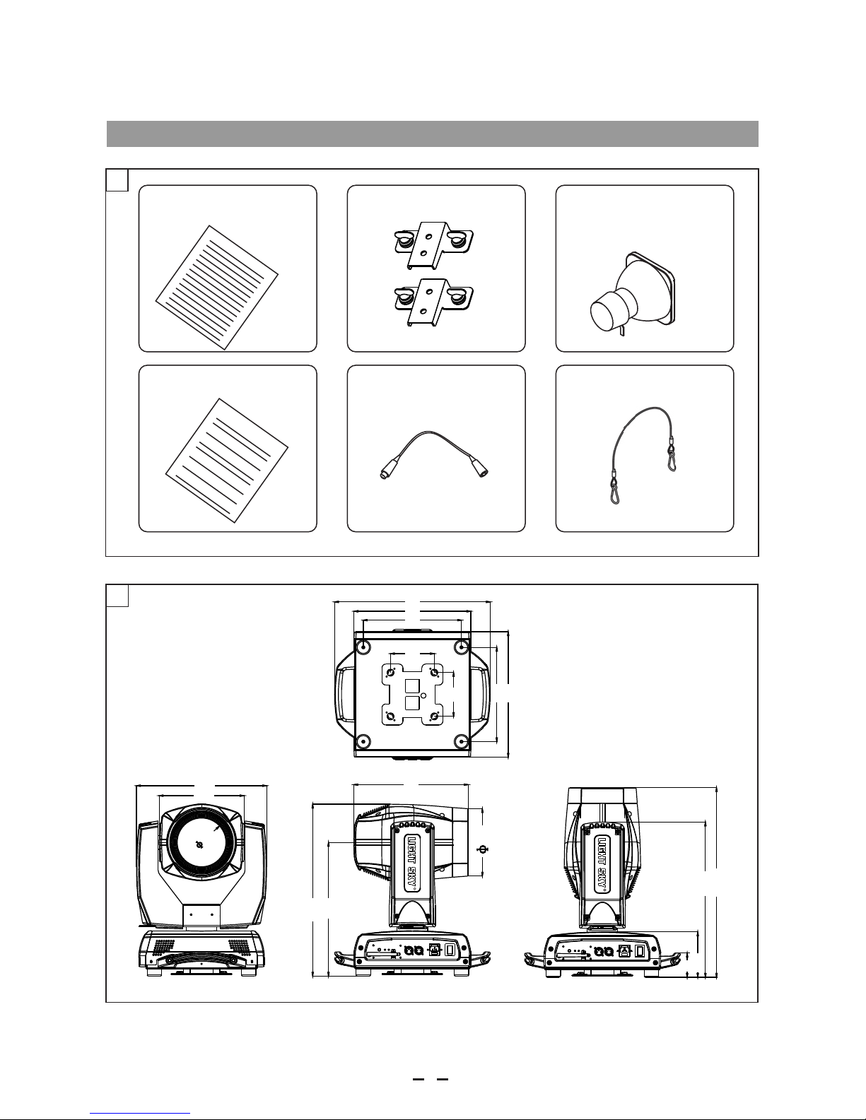
Attachmentcontents- Fig. 1
2
Body Size---Fig 2
4
9
8
119
300
4
5
2
3
5
1
342
223
128
1 15
115
258
2
4
8
7
7
409
33
0
307
4
0
8
6
4
1
ATTACHMENT AND BODY SIZE
4
LAMP
1
SAFETY CORD
DMX CABLE
WARRANTY CARD
USER MANUAL
BRACKET
(fitted into projector)
R
R
www.tourprolighting.com

Installing the projector- Fig. 3
The projector can be installe
WARNING:with the exception of when the projector is positioned on the floor, the safety cable must be fitted.
This must be securely fixed to the support structure of the projector and then connected to the fixing point at
the centre of the base.
d on the floor resting on special rubber feet, on a truss or on the ceiling or wall.
3
L
N
Mains
4
Connecting to the ma ins suppp ly ---Fig 4
INSTALLATION AND CONNECTING
5
Minimum dist ance to f lamma ble mat erial =12m.
Minimum dist ance to i llumi nated s urfac e=
Maximum ambi ent tem perat ure t = 33℃.
a
Always disco nnect f rom mai ns befo re repl acing
the lamp.
Caution:Ho t lamp. Al low to co ol for 30 m inute s
before openi ng.
Exterior sur face te mpera ture un der ste ady
state condit ion =45 .
Prolonged ex posur e to unsh ielde d
lamp can cause e ye and sk in burn s.
℃
12m
WARNIN G:HOT!
ENTER
UP
DOWN
R
LIGHT SKY
R
R
www.tourprolighting.com
 Loading...