

Page 1
Telran TDK Kit User
Guide
connected freedom
Telran TDK TZ2070-IFU_v2.02
Sep 2011
Toumaz UK Limited
Building 3, 115 Milton Park,
Abingdon,
OX14 4RZ, UK
Tel: +44 1235 438 950
Email:
info@ www.toumaz.com
Toumaz Asia
11F No. 285, Sec 2, Tiding
Blvd. Neihu District, Taipei
Tel: +886 2 2799 8108
Page 2

connected freedom
Copyright 2011 Toumaz UK Limited
This document contains and refers to proprietary information, which is protected by copyright.
Reproduction of any part of this document is prohibited without the prior written permission of Toumaz
UK Limited.
Notices
Information contained in this publication regarding the Telran TZ1053 and the Telran TDK is provide
as-is and may be superseded by updates. It is the Users responsibility to see that his/hers
applications meets their own specifications.
TOUMAZ MAKES NO REPRESENTATIONS OR WARRANTIES OF ANY KIND WHETHER
EXPRESS OR IMPLIED, WRITTEN OR ORAL, STATUTORY OR OTHERWISE, RELATED TO THE
INFORMATION, INCLUDING BUT NOT LIMITED TO ITS CONDITION, QUALITY, PERFORMANCE,
MERCHANTABILITY OR FITNESS FOR PURPOSE.
Toumaz disclaims all liability arising from this information and its use. Use of Toumaz’s products as
critical components in life support systems is not authorized except with express written approval by
Toumaz. No licenses are conveyed, implicitly or otherwise, under any Toumaz intellectual property
rights.
All information in this document is subject to change without notice. The products supplied may differ
in appearance from that shown.
Trademarks
The Toumaz™ name and logo, and Telran™ are registered trademarks of Toumaz UK Limited.
The Microchip name and logo, KEELOQ, MPLAB, PIC, are the registered trademarks of Microchip
Technology Incorporated.
UMI and the UMI logo are trademarks of Cambridge Consultants Ltd.
All other trademarks mentioned herein are the property of their respective companies
Document Revision History
Issue Description Author Date
1.00 First Version for Telran TDK AM 20-Jan-2011
2.00 Updated for Version 2 TDKs AM 06-Jul-2011
2.01 Updated for Version 2 TDKs AM 10-Aug-2011
2.02 Safety Information Updated AM 22-Sep-2011
TZ2070-IFU ver 2.02 Sep 2011 Page 2 of 58
Page 3

Contents
connected freedom
1.
1.1
1.2
1.3
1.4
1.5
1.6
1.7
2.
2.1
2.2
2.2.1
2.2.2
2.2.3
2.3
2.3.1
Copyright 2011 Toumaz UK Limited ............................................................................... 2
Notices ................................................................................................................................ 2
Trademarks ......................................................................................................................... 2
Document Revision History ................................................................................................ 2
Contents ............................................................................................................................. 3
Figures ................................................................................................................................ 5
Introduction ......................................................................................................................... 6
Document Layout................................................................................................................ 6
Screen Displays .................................................................................................................. 7
Conventions Used in this Guide ......................................................................................... 7
Recommended Reading ..................................................................................................... 7
The Toumaz Web Site ........................................................................................................ 7
Abbreviations ...................................................................................................................... 8
Customer Support............................................................................................................... 8
Regulatory Approval ........................................................................................................... 9
USA .................................................................................................................................... 9
Canada ............................................................................................................................. 10
Radio Frequency Module ................................................................................................. 10
USB Dongle ...................................................................................................................... 10
Sensor Development Board ............................................................................................. 10
Europe .............................................................................................................................. 11
Helpful Web Sites: ............................................................................................................ 12
3.
3.1
3.2
3.3
3.4
3.5
3.5.1
3.5.1.1
3.5.1.2
3.5.1.3
3.5.1.4
3.5.1.5
3.5.1.6
3.5.2
3.5.2.1
3.5.2.2
3.5.2.3
3.5.2.4
3.5.2.5
3.5.2.6
3.5.2.7
3.5.2.8
3.5.2.9
3.5.2.10
3.5.3
3.5.3.1
3.5.3.2
3.5.3.3
3.5.3.4
Telran TDK Kit Contents ................................................................................................... 13
Deliverables ...................................................................................................................... 13
Electrostatic Warning ........................................................................................................ 14
Safety Notice .................................................................................................................... 14
Waste Electrical and Electronic Equipment (WEEE)........................................................ 14
Telran TDK Hardware Features ....................................................................................... 15
Telran TDK RF Module (RFM). ........................................................................................ 15
RFM Assembly Details ..................................................................................................... 15
RFM Block Diagram ......................................................................................................... 16
RFM Board Dimensions ................................................................................................... 16
RFM Board Weights ......................................................................................................... 16
J1 U_FL Co-axial Antenna Connector .............................................................................. 16
J2 Telran TDK External Connector................................................................................... 17
Telran TDK USB Dongle .................................................................................................. 18
USB Assembly Details ...................................................................................................... 18
USB Board Dimensions .................................................................................................... 19
USB Board Weights .......................................................................................................... 19
USB Block Diagram. ......................................................................................................... 19
J1 U_FL Co-axial Antenna Connector .............................................................................. 20
J2 Telran TDK External Connector................................................................................... 20
J5 PIC ISP Connector ...................................................................................................... 20
LEDs ................................................................................................................................. 21
TDK USB Dongle & Connections to a PC ........................................................................ 22
USB UART Routing .......................................................................................................... 22
Telran TDK Sensor Development Board (SDB) ............................................................... 23
SDB Assembly Details ...................................................................................................... 23
SDB Board Dimensions .................................................................................................... 24
SDB Board Weights .......................................................................................................... 24
SDB Block Diagram .......................................................................................................... 24
TZ2070-IFU ver 2.02 Sep 2011 Page 3 of 58
Page 4

connected freedom
3.5.3.5
3.5.3.6
3.5.3.7
3.5.3.8
3.5.3.9
3.5.3.10
3.5.3.11
3.5.3.12
3.5.4
4.
4.1
4.2
4.3
5.
5.1
5.2
6.
6.1
6.1.1
6.1.2
6.2
7.
7.1
7.2
7.3
J5 PIC ISP Connector ...................................................................................................... 24
J6 UMI+ Connector ........................................................................................................... 25
J7 Telran TDK RF Board Connector ................................................................................ 25
J10 1.25V Jumper............................................................................................................. 25
J11 External Power Supply / Monitor Connector .............................................................. 26
J12 LED Enable/Disable Jumper...................................................................................... 26
J13 USART2 Connector ................................................................................................... 26
LEDs ................................................................................................................................. 27
RFM with SDB. ................................................................................................................. 27
Getting Started.................................................................................................................. 28
What’s On The CD............................................................................................................ 28
Software Tools .................................................................................................................. 28
Toumaz Wireless Tool ...................................................................................................... 29
Accelerometer Demo Program ......................................................................................... 30
Installation of the Accelerometer Demonstration Program. .............................................. 31
Operation of the Accelerometer Demonstration Program. ............................................... 31
Customisation ................................................................................................................... 34
The Scripter ...................................................................................................................... 34
What is a Script?............................................................................................................... 34
The Telran Demo .............................................................................................................. 34
Using the Bootstrap Loader. ............................................................................................. 36
Reference Design Schematic Diagrams .......................................................................... 41
TDK RF Board TZ207010 ................................................................................................. 41
TDK USB Board TZ207020 .............................................................................................. 42
TDK Sensor Board TZ207030 .......................................................................................... 47
A1.
A2.
A3.
Appendices ....................................................................................................................... 52
Installing the Bootstrap Loader. ........................................................................................ 52
Configuring the Toumaz GUI. ........................................................................................... 56
Configuring BareTail. ........................................................................................................ 57
TZ2070-IFU ver 2.02 Sep 2011 Page 4 of 58
Page 5

connected freedom
Figures
Figure 1. Telran TDK RF Assembly Views. .......................................................................................... 15
Figure 2. Telran TDK RFM Block Diagram ........................................................................................... 16
Figure 3. Telran TDK USB Board Assembly Details ............................................................................. 18
Figure 4. Telran TDK USB Board Block Diagram ................................................................................. 19
Figure 5. Location of LEDs on Telran TDK USB Board ........................................................................ 21
Figure 6. UART Routing as Controlled by PIC_UART_SEl. ................................................................. 22
Figure 7. Telran TDK Sensor Development Board ............................................................................... 23
Figure 8. Telran TDK SDB Block Diagram ............................................................................................ 24
Figure 9. Location of LEDs on Telran TDK Sensor Board. ................................................................... 27
Figure 10. RFM Plugged into SDB. ....................................................................................................... 27
Figure 11. Application in operation. ...................................................................................................... 30
Figure 12. File structure for Accelerometer Demonstration. ................................................................. 31
Figure 13. Application Screen opening and looking for target. ............................................................. 32
Figure 14 Logs showing Base station looking for target ....................................................................... 32
Figure 15 TELRAN RF Module and Sensor Development Board ........................................................ 32
Figure 16. Application running with linked target. ................................................................................. 33
Figure 17 Accelerometer demo application script loaded in TELRAN script compiler ........................ 34
Figure 18 Byte Code for Accelerometer demo application ................................................................... 35
Figure 19. Bootstrap Loader Opening Screen. ..................................................................................... 36
Figure 20. Finding the Bootstrap Loader Settings. ............................................................................... 37
Figure 21. Bootstrap Loader Settings Window. .................................................................................... 37
Figure 22. Bootstrap Loader Pause Application Program. ................................................................... 38
Figure 23 Bootstrap Connected. ........................................................................................................... 39
Figure 24. Locating the User Code. ...................................................................................................... 39
Figure 25. Programming Complete. ...................................................................................................... 40
Figure 26. PICkit™ 2 opening screen shot. .......................................................................................... 52
Figure 27. PICkit™ 2 connected to the PIC18LF25K22 on the TDK USB Board or TDK Sensor Board.
....................................................................................................................................................... 53
Figure 28. Selecting an Import Hex File. ............................................................................................... 53
Figure 29. Locating the ‘PIC 18 Bootloader.HEX’ file. .......................................................................... 54
Figure 30. ‘PIC 18 Bootloader.HEX’ file Imported................................................................................. 54
Figure 31. Programming Complete. ...................................................................................................... 55
Figure 32. BareTails Opened. ............................................................................................................... 57
Figure 33. Highlighting Window. ............................................................................................................57
Figure 34. Set String to be Highlighted. ................................................................................................ 58
Figure 35. Highlighting Completed. ....................................................................................................... 58
TZ2070-IFU ver 2.02 Sep 2011 Page 5 of 58
Page 6

1. Introduction
The Telran TDK kit serves as a development and evaluation tool for the Telran TZ1053 RF
device. The boards contained in this kit have sufficient features and expandability to allow the
user to explore all of the features of the Telran TZ1053.
This document is applicable to the Telran TDK Version 2
This section of the User Guide contains general information that will be useful to know before
using the Telran TDK Kit contents. Items discussed in this chapter include:
• Document Layout
• Conventions Used in this Guide
• Recommended Reading
• The Toumaz Web Site
• Customer Support
• Document Revision History
1.1 Document Layout
This document describes how to evaluate and use the Telran TZ1053 device by using the
hardware within Telran TDK kit. The User guide layout is as follows:
Section: 1 Introduction
This section of the User Guide contains general information that will be useful to
know.
Section: 2. Regulatory Approval
This section indicates the current Regulatory Approval Status.
Section: 3 Telran TDK Kit Contents
This section describes features of the hardware in the Telran TDK Kit.
Section: 4. Getting Started
This section goes through the basic step-by-step process for getting the Telran
TDK Kit working
Section: 5. Accelerometer Demo Program
This section describes the installation and operation of the Accelerometer Demo
for the Telran TDK Kit.
Section: 6. Customisation
This section details the processes required to customise the Telran TDK
Demonstration program. his section also guides the User through the steps
required to produce Script based program.
Section 7. Reference Design Schematic Diagrams
This section presents the schematic diagrams of each of boards that go to make
up the Telran TDK kit.
TZ2070-IFU ver 2.02 Sep 2011 Page 6 of 58
Page 7

Description
Represents
Examples
•
Section to be
1.2 Screen Displays
The screen displays in this document are representative of what will be seen by the User
when running the various programs described in this document. Actual screens may differ as
program versions change or are updated.
1.3 Conventions Used in this Guide
Section to be completed.
References
Italic character
Emphasised text
TZ1053 Telran
datasheet V1_06
draft.doc.
completed.
Text in angle brackets <> A key on the keyboard Press <Enter>
Underlined text in blue Hyper link to a website Toumaz
1.4 Recommended Reading
• TZ1053 Telran datasheet
• TZ1053 Software User Guide
•
UMI (Universal Metering Interface) Overview document: eSmart-M-004
v2.1.doc
For more information regarding the Telran TZ1053 device please refer to the Toumaz web
site.
from Cambridge Consultants Ltd.
1.5 The Toumaz Web Site
Toumaz provides online support for registered customers / users through the ‘extranet’ at
www.toumaz.com. This web site is used as a means to make files and information easily
available to customers.
The Toumaz web site is accessible by using an Internet browser and clicking on the ‘extranet’
menu item. The User can the either log on or register with the Toumaz website.
The web site contains the following information:
Product Support – Data sheets and errata, application notes and sample programs, design
resources, user’s guides and hardware support documents, latest software releases and
archived software.
General Technical Support – Frequently Asked Questions (FAQs), technical support requests.
TZ2070-IFU ver 2.02 Sep 2011 Page 7 of 58
Page 8

1.6 Abbreviations
The following abbreviations are used within this document.
CE Conformité Européenne – conformance marking
CRC Cyclic Redundancy Check
FAE Field Application Engineer
FCC Federal Communications Commission - US
GPIO General Purpose Input Output
ISM Industrial Scientific and Medical
ISP In System Programming
ITU International Telecommunications Union
ITU-T ITU – Telecommunications
MAC Media Access Controller
NSP Network Service Protocol
NSP Nanopower Sense Protocol
OTA Over The Air
PCB Printed Circuit Board
RF Radio Frequency
RFM Radio Frequency Module
RX Receiver
SDB Sensor Development Board
SPI System Packet Interface
TDK Telran development Kit
TX Transmitter
UMI Universal Metering Interface
USART Universal Synchronous Asynchronous Receiver Transmitter
USB Universal Serial Bus
1.7 Customer Support
Users of Toumaz products can receive support through a number ways:
Distributor or Representative
Local Sales Office
Field Application Engineer (FAE)
Technical Support
TZ2070-IFU ver 2.02 Sep 2011 Page 8 of 58
Page 9

2. Regulatory Approval
The Telran TDK RF module, TZ207010 and Telran TDK USB module, TZ20720 have
undergone testing for regulatory approvals in Europe, the United States and other countries.
FCC modular approval will allow the end user to place the Telran TDK RF module, TZ207010
inside a finished product and not require regulatory testing for an intentional radiator (RF
transmitter), provided no changes or modifications are made to the module circuitry. Changes
or modifications could void the user’s authority to operate the equipment. The end user must
comply with all of the instructions provided by the Grantee, which indicate installation and/or
operating conditions necessary for compliance.
The integrator may still be responsible for testing the end product for any additional
compliance requirements required with this module installed (for example: digital device
emission, PC peripheral requirements, etc.) in the specific country that the end device will be
marketed.
2.1 USA
The Telran TDK RF module, TZ207011 has received Federal Communications Commission
(FCC) CFR47 Telecommunications, Part 15 Subpart C “Intentional Radiators” 15.247 and
modular approval in accordance with FCC Public Notice DA 00-1407 Released: June 26,
2000, Part 15 Unlicensed Modular Transmitter Approval. The Telran TDK RF module,
TZ207011 module can be integrated into a finished product without obtaining subsequent and
separate FCC approvals for intentional radiation.
The Telran TDK RF module, TZ207011 module has been labelled with its own FCC ID
number, and if the FCC ID is not visible when the module is installed inside another device,
then the outside of the finished product into which the module is installed must also display a
label referring to the enclosed module. The following examples present terminology that could
be used: A user’s manual for the product should include the following statement:
Contains Transmitter Module FCC ID: ZT9-TZ207011V2.
or
Contains FCC ID: ZT9-TZ207011V2. This device complies with Part 15 of the FCC Rules.
Operation is subject to the following two conditions:
(1) This device may not cause harmful interference, and
(2) This device must accept any interference received, including interference that may
cause undesired operation. This equipment has been tested and found to comply with
the limits for a Class B digital device, pursuant to part 15 of the FCC Rules. These
limits are designed to provide reasonable protection against harmful interference in a
residential installation. This equipment generates uses and can radiate radio
frequency energy, and if not installed and used in accordance with the instructions,
may cause harmful interference to radio communications. However, there is no
guarantee that interference will not occur in a particular installation. If this equipment
does cause harmful interference to radio or television reception, which can be
determined by turning the equipment off and on, the user is encouraged to try to
correct the interference by one or more of the following measures:
• Reorient or relocate the receiving antenna.
• Increase the separation between the equipment and receiver.
• Connect the equipment into an outlet on a circuit different from that to
which the receiver is connected.
• Consult the dealer or an experienced radio/TV technician for help.
TZ2070-IFU ver 2.02 Sep 2011 Page 9 of 58
Page 10

2.2 Canada
2.2.1 Radio Frequency Module
Canada IC: 9809A-TZ207011V2
This Class B digital apparatus meets all requirements of the Canadian Interference Causing
Equipment Regulations. Operation is subject to the following two conditions: (1) this device
may not cause harmful interference, and (2) this device must accept any interference
received, including interference that may cause undesired operation.
Cet appareillage numérique de la classe [B] répond à toutes les exigences de l'interférence
canadienne causant des règlements d'équipement. L'opération est sujette aux deux
conditions suivantes: (1) ce dispositif peut ne pas causer l'interférence nocive, et (2) ce
dispositif doit accepter n'importe quelle interférence reçue, y compris l'interférence qui peut
causer l'opération peu désirée.
2.2.2 USB Dongle
Canada IC: 9809A-TZ207021V2
This Class B digital apparatus meets all requirements of the Canadian Interference Causing
Equipment Regulations. Operation is subject to the following two conditions: (1) this device
may not cause harmful interference, and (2) this device must accept any interference
received, including interference that may cause undesired operation.
Cet appareillage numérique de la classe [B] répond à toutes les exigences de l'interférence
canadienne causant des règlements d'équipement. L'opération est sujette aux deux
conditions suivantes: (1) ce dispositif peut ne pas causer l'interférence nocive, et (2) ce
dispositif doit accepter n'importe quelle interférence reçue, y compris l'interférence qui peut
causer l'opération peu désirée.
2.2.3 Sensor Development Board
Canada IC: 9809A-TZ207030V2
This is Class B digital apparatus complies with Canadian ICES-003.
Cet appareil numérique de la classe B est conforme à la norme NMB-003 du Canada.
TZ2070-IFU ver 2.02 Sep 2011 Page 10 of 58
Page 11
RTTE article
Relevant Standard
Chief Technology Officer
Regulatory and QA
2.3 Europe
The Telran TDK RF module, TZ207010 module has been certified for use in European
countries. The following is Toumaz’s R&TTE Declaration of Conformity:
R&TTE Declaration of Conformity
Toumaz UK Ltd, Building 3, 115, Milton Park, Abingdon, Oxon OX14 4RZ, UK declares that
the following product:
TELRAN 868MHz TDK Kit TZ207000 (TZ1053TDK868), comprising of the following modules:
• 868MHz TDK RF Module TZ207010
• 868MHz TDK USB dongle TZ207020
• 868MHz TDK Sensor Dev. PCB TZ207030
is in conformity with the essential requirements and other relevant requirements of the R&TTE
Directive 95/5/EC.
The product has been assessed under annex IV by notified body TUV SUD Ltd (CE0168) and
is in conformity with the following standards:
Article 3.1 (Safety) IEC 60950-1:2006/A1:2010
Article 3.1.b (EMC) EN 301489-1 v2.3.1 referencing EN 301489-3 v1.4.1
Article 3.2 (Spectrum) EN 300220-1 v2.3.1 referencing EN 300220-2
Signed on behalf of Toumaz UK Ltd
TZ2070-IFU ver 2.02 Sep 2011 Page 11 of 58
Page 12

ETSI does not provide a modular approval similar to the USA (FCC) and Canada (IC).
However, the declaration of conformity above can be used as part of the customer’s
application for certification. The test report data can be included in their test plan and can
significantly the lower customer’s certification burden.
A helpful document that can be used as a starting point in understanding the use of Short
Range Devices (SRD) in Europe is the European Radio Communications Committee (ERC)
Recommendation “70-03 E”, downloadable from the European Radio Communications Office
(ERO): http://www.ero.dk/
The end user is responsible for ensuring compliance with harmonized frequencies and
labelling requirements for each country in which the end device is marketed and sold.
2.3.1 Helpful Web Sites:
Federal Communications Commission (FCC): http://www.fcc.gov
Radio and Telecommunications Terminal Equipment (R&TTE):
ttp://ec.europa.eu/enterprise/rtte/index_en.htm
European Conference of Postal and Telecommunications Administrations (CEPT):
http://www.cept.org/
European Telecommunications Standards Institute (ETSI): http://www.etsi.org/
European Radio Communications Office (ERO): http://www.ero.dk/
TZ2070-IFU ver 2.02 Sep 2011 Page 12 of 58
Page 13
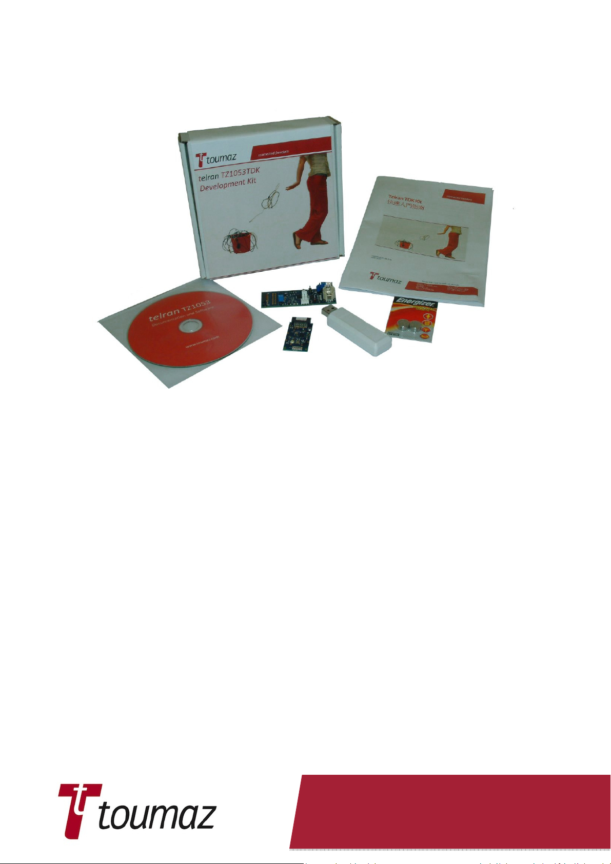
3. Telran TDK Kit Contents
3.1 Deliverables
The Telran TDK kit contains the following items:
Telran TDK RF Module, TZ20701x.
Telran TDK USB Dongle, TZ20702x.
Telran TDK Senor Development Board, TZ207030.
The Telran TDK Kit DVD, containing User Guide, Software application notes and the Windows
Based Telran Wireless Tool.
The x above in the board number refers to the base frequency of operation of the unit. Thus:
Where x = 0, i.e. TZ207010 and TZ207020 the base frequency will be 868 MHz, (ITU Region 1),
Where x = 1, i.e. TZ207011 and TZ207021 the base frequency will be 915 MHz, (ITU Region 2),
Where x = 2, i.e. TZ207012 and TZ207022 the base frequency will be 950 MHz.
Where x = 3, i.e. TZ207013 and TZ207023 the base frequency will be 779 MHz.
This document will refer to TZ207010 and TZ207030 throughout. It should be understood that
where a kit is supplied at a different frequency for example 915 MHz comments made about
TZ207010 and TZ207020 apply equally to TZ207011 and TZ207021, respectively. This applies
equally for other frequency Telran TDK kits.
Note: Telran TDK Sensor Development Board, TZ207030, does not contain any radio frequency
dependant parts and thus will be the same in each kit.
TZ2070-IFU ver 2.02 Sep 2011 Page 13 of 58
Page 14

3.2 Electrostatic Warning
The Telran TDK kit components are supplied in a protective anti-static package. The boards
comprising the TDK Kit must not be subjected to high electrostatic potentials. A grounding strap
or similar anti-static protective device should be worn when handling these items. Avoid touching
the components on the TDK boards.
Static sensitive components are used on the Patch PCBA and therefore handling of this unit
shall be in accordance with ESD Handling Procedures.
ESD Symbol
3.3 Safety Notice
The Telran TDK kit contains a USB Dongle this is supplied with power via the USB connector.
The USB Dongle can be connected directly to a desktop or laptop PC, or via an USB extension
cable of not more than 1 m in length. The USB Dongle can also be connected via a self-powered
or powered USB Hub to a desktop or laptop PC.
To avoid the risk of electric shock or fire hazard ensure that any external power source used
with the USB Dongle or the Sensor Development Board and RF Module Combination must meet
the requirements of IEC 60950-1 clause 2.1.1.5, Limited Energy and source must also meet the
requirements of IEC 60950-1 clause 2.5, Limited Power Sources. The PSU used with the USB
should be voltage and current limited to 5V@50mA. The PSU used with the Sensor
Development Board and RF Module Combination should be voltage and current limited to
3V@50mA
3.4 Waste Electrical and Electronic Equipment (WEEE)
Important:
This symbol is placed on the product to remind users to dispose of Waste Electrical
and Electronic Equipment (WEEE) appropriately, per Directive 2002-96-EC. In most
areas, this product can be recycled, reclaimed and reused when properly
discarded. Do not discard labelled units with general waste. For information about
proper disposal, contact your Toumaz Distributor or representative, or visit
www.toumaz.com.
TZ2070-IFU ver 2.02 Sep 2011 Page 14 of 58
Page 15
3.5 Telran TDK Hardware Features
The layouts of each board in the Telran TDK Kit are shown in the following sections, with a list of
the main features. More complex features are discussed later.
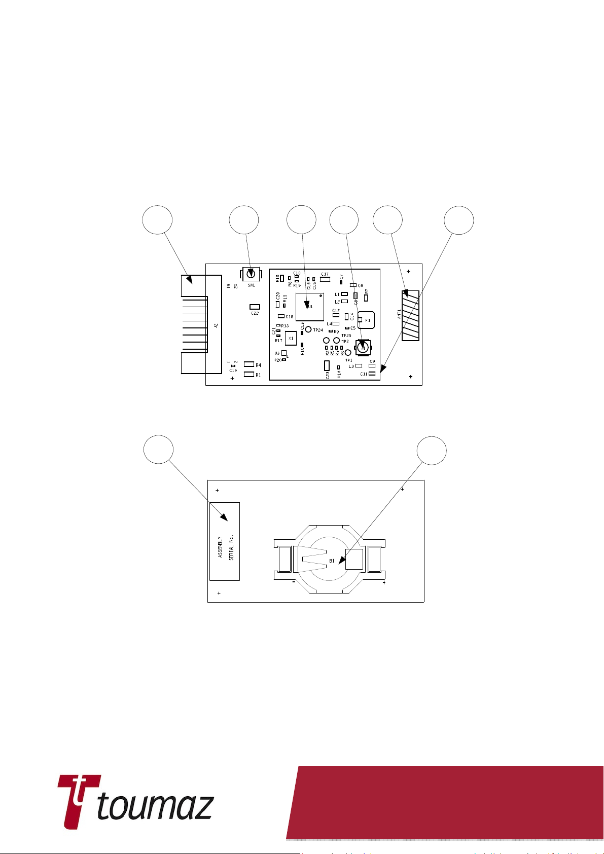
3.5.1 Telran TDK RF Module (RFM).
3.5.1.1 RFM Assembly Details
1 2
8
3
4 5
View on Top of PCB
7
6
View on Underside of PCB
Figure 1. Telran TDK RF Assembly Views.
1. J2 Connector to Telran TDK Sensor Board.
2. Telran Reset.
3. Telran TZ1053.
4. J1 U FL RF Connector.
5. Antenna.
6. LR44 Battery Retainer (Not normally fitted).
7. Outline of RF Can (Fitted to 915MHz RF Modules)
8. Assembly Labels
TZ2070-IFU ver 2.02 Sep 2011 Page 15 of 58
Page 16
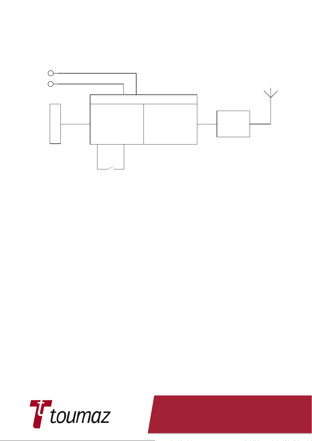
3.5.1.2 RFM Block Diagram
VBatt/Vchip
VDDIO
Telran 1053
GPIOs
Digital
RF
Antenna
Matching
Connector
Reset
Figure 2. Telran TDK RFM Block Diagram
3.5.1.3 RFM Board Dimensions
4 layer PCB 22 mm x 39 mm x 1.0 mm. Length overall, including connector 43.74 mm.
3.5.1.4 RFM Board Weights
EU Version, TZ207010: Weight: 2.8 gms without battery or Battery Holder
Weight: 3.7 gms with Battery Holder and no battery
Weight: 5.1 gms with Battery Holder and battery
US Version, TZ207011: Weight: 5.9 gms with RF Can, Battery Holder and no battery fitted
Weight: 7.8 gms with RF Can and Battery Holder with battery fitted.
3.5.1.5 J1 U_FL Co-axial Antenna Connector
A ‘Unique’ connector for connecting to external antennas. Note for full power to be delivered to
an antenna attached to this connector C9 must be removed from the PCB.
TZ2070-IFU ver 2.02 Sep 2011 Page 16 of 58
Page 17

Pin
No. Function
Pin No.
Function
3.5.1.6 J2 Telran TDK External Connector
1 VDDIO 2 MISO_TEL
3 F0 4 MOSI_TEL
5 GND 6 SPI_CLK
7 GND 8 SPI_CS_N
9 TEL_GPIO4 10 TEL_RESET
11 SLPTMR 12 TEL_GPIO0
13 TEL_GPIO1 14 TEL_GPIO2
15 TEL_GPIO3 16 Vchip
17 Reserved 18 Reserved
19 Reserved 20 Reserved
TZ2070-IFU ver 2.02 Sep 2011 Page 17 of 58
Page 18
3.5.2 Telran TDK USB Dongle
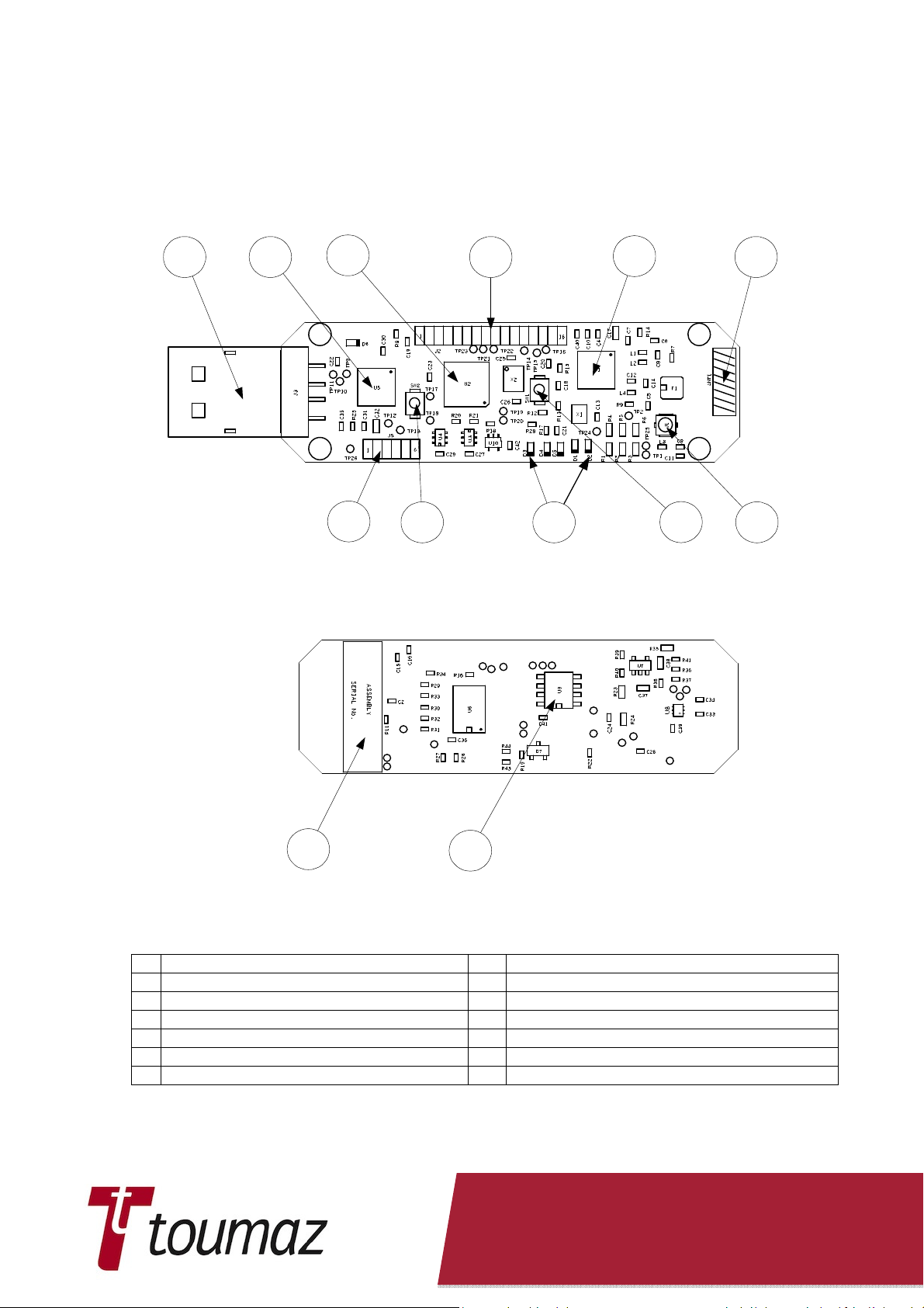
3.5.2.1 USB Assembly Details
1
2
3
7
8
4
5
10
6
119
View on Top of PCB
12
13
View on Underside of PCB
Figure 3. Telran TDK USB Board Assembly Details
1. J3 USB Connector. 8. PIC Reset pushbutton.
2. FTDI USB Interface Chip. 9. LEDs
3. PIC18LF25K22. 10. Telran Reset pushbutton
4. J2 Telran TDK External Connector. 11. J1 U_FL co-axial antenna connector
5. Telran TZ1053. 12. Assembly Labels
6. Antenna. 13. SPI Memory (23K256)
7. J5 PIC ISP.
TZ2070-IFU ver 2.02 Sep 2011 Page 18 of 58
Page 19

3.5.2.2 USB Board Dimensions
4 layer PCB 18.68 mm x 61.47 mm x 1.0 mm.
3.5.2.3 USB Board Weights
USB Dongle (TZ207020 and TZ207021) Weight: 10.3 gms
3.5.2.4 USB Block Diagram.
5 x
ISP Port, J5
PIC Reset, SW2
PIC
LEDs
SPI Bus &
Control
SPI Memory
USBConnector, J3
USB
Interface
Telran
TZ1053
Serial Routing
Circuitry
USB Serial
Data
Figure 4. Telran TDK USB Board Block Diagram
Antenna
Matching
J2 Telran TDK
External
Connector
TZ2070-IFU ver 2.02 Sep 2011 Page 19 of 58
Page 20

Pin No.
Function
Pin No.
Function
Pin No.
Function
3.5.2.5 J1 U_FL Co-axial Antenna Connector
A ‘Unique’ connector for connecting to external antennas. Note for full power to be delivered to
an antenna attached to this connector C9 must be removed from the PCB.
3.5.2.6 J2 Telran TDK External Connector
1 VDDIO 2 MISO_TEL
3 F0 4 MOSI_TEL
5 GND 6 SPI_CLK
7 GND 8 SPI_CS_N
9 TEL_GPIO4 10 TEL_RESET
11 SLPTMR 12 TEL_GPIO0
13 TEL_GPIO1 14 TEL_GPIO2
15 TEL_GPIO3 16 Vchip
Connector J2 is not normally fitted.
3.5.2.7 J5 PIC ISP Connector
1 VPP
2 VDDPIC
3 GND
4 PGD
5 PGC
6 Unconnected
J5 is used to program the PIC on the Telran TDK USB Board.
TZ2070-IFU ver 2.02 Sep 2011 Page 20 of 58
Page 21

3.5.2.8 LEDs
The location and function of LEDs on the Telran TDK USB board is shown in Figure 5.
Power LED
TEL_GPIO4
TEL_GPIO2
TEL_GPIO3
TEL_GPIO0
TEL_GPIO1
Figure 5. Location of LEDs on Telran TDK USB Board
The LED Functionality is shown in the following table:
LED Telran Pin No. As Telran Function pin(s) As Telran Status Pin
D3 TEL_GPIO4 GPIO/1 wire protocol Radio Busy
D2 TEL_GPIO0 GPIO/UART TX D1 TEL_GPIO1 GPIO/UART RX D5 TEL_GPIO2 GPIO/(I2C) SDA Needs Attention
D4 TEL_GPIO3 GPIO/(I2C) SCL CPU Busy
See
TZ1053 Telran datasheet
and
TZ1053 Software User Guide
for further details.
TZ2070-IFU ver 2.02 Sep 2011 Page 21 of 58
Page 22

3.5.2.9 TDK USB Dongle & Connections to a PC
The TDK USB Dongle may be plugged directly into a USB port of a Desktop PC or Laptop. An
extension cable of not more than 1m in length may be also used to connect the TDK USB
Dongle to a Desktop PC or Laptop.
The TDK USB Dongle may also be plugged into a USB hub that is subsequently connected to a
Desktop PC or Laptop.
3.5.2.10 USB UART Routing
UART SEL = 0
Telran
TZ1053
UART SEL = 1
(Default)
PIC18LF25K22
USART1 USART2
USB
PIC18LF25K22
USART1 USART2
Telran
TZ1053
Figure 6. UART Routing as Controlled by PIC_UART_SEl.
TZ2070-IFU ver 2.02 Sep 2011 Page 22 of 58
USB
Page 23

3.5.3 Telran TDK Sensor Development Board (SDB)
3.5.3.1 SDB Assembly Details
1 2
16
3
9
10 11 12
4
5
6
13
7
14 15
8
View on Top of PCB
17
18
View on Underside of PCB
Figure 7. Telran TDK Sensor Development Board
1. J7 Connector to Telran TDK RF Board. 10. Jumper J10.
2. J6 UMI+ Connector (see for pin out). 11. PIC18LF25K22.
3. Accelerometer 3 axis LIS35DE +/-2g, +/-8g 12. Jumper J11.
4. PIC Reset. 13. Battery On/Off Switch SW1.
5. J5 PIC ISP Connector. 14. LEDs.
6. User Push button. 15. LR44 Battery Retainer.
7. Jumper J12. 16. Assembly Labels.
8. J13 USART2 Connector. 17. SPI Memory (Not Fitted).
9. 32k678Hz Oscillator. 18. Alternative 3 axis accelerometer – LI35DH
(Not Fitted).
TZ2070-IFU ver 2.02 Sep 2011 Page 23 of 58
Page 24

Pin No.
Function
3.5.3.2 SDB Board Dimensions
4 layer PCB 27.0 mm x 75.0 mm x 1.0 mm.
3.5.3.3 SDB Board Weights
Weight: 7.7 gms without battery fitted.
Weight: 9.6 gms with battery fitted
3.5.3.4 SDB Block Diagram
Sensor Board Break
Out Connector, J6
Sensor Board To RF
Module Connector,
J7
32k768Hz
Oscillator
ISP Port, J5
UART Port,
J13
Battery and Voltage
Boost Circuitry
5 x
LEDs
PIC
User Pushbutton,
SW2
SPI Bus
SPI Memory
Chip Select
SPI
Accelerometer
Chip Select
Steering
Circuitry
Figure 8. Telran TDK SDB Block Diagram
3.5.3.5 J5 PIC ISP Connector
1 VPP
2 VDDPIC
3 GND
4 PGD
5 PGC
6 Unconnected
J5 is used to program the PIC on the Telran TDK Sensor Board.
TZ2070-IFU ver 2.02 Sep 2011 Page 24 of 58
Page 25

Pin No.
Function
Pin No.
Function
Pin No.
Function
Pin No.
Function
3.5.3.6 J6 UMI+ Connector
The UMI+ Connector is a connector that is configured to provide connections to the Universal
Metering Interface.
1 VDDIO 2 MISO_TEL
3 F01 4 MOSI_TEL
5 GND 6 SPI_CLK
7 GND 8 SPI_CS_N
9 TEL_GPIO4 10 TEL_RESET
11 SLPTMR 12 TEL_GPIO0
13 TEL_GPIO1 14 TEL_GPIO2
15 TEL_GPIO3 16 Vchip
Note:
Pin 3 - F0 is not a UMI pin as this is used by High power UMI devices.
Pins 1 to 10 are configured as UMI connections, whilst the remaining pins can be used to
connect to other functions on the Telran TDK RF and Telran TDK Sensor Boards.
3.5.3.7 J7 Telran TDK RF Board Connector
1 VDDIO 2 MISO_TEL
3 F0 4 MOSI_TEL
5 GND 6 SPI_CLK
7 GND 8 SPI_CS_N
9 TEL_GPIO4 10 TEL_RESET
11 SLPTMR 12 TEL_GPIO0
13 TEL_GPIO1 14 TEL_GPIO2
15 TEL_GPIO3 16 Vchip
17 Reserved 18 Reserved
19 Reserved 20 Reserved
This table shows the correct pinout of J7. The pin numbering indicated on the TZ207020 PCB
is incorrect, with 1 and 20 swapped.
3.5.3.8 J10 1.25V Jumper
J10 is linked to supply the Vchip of an attached Telran TDK RF Board with 1.25V when a
battery or external power supply is used to power the Telran TDK Sensor Board.
A current meter placed across J10, when it is unlinked, can be used to monitor the current
used by an attached Telran TDK RF Board.
Note:
Jumper J10 should not be linked when supplying Vchip from Connector J11.
TZ2070-IFU ver 2.02 Sep 2011 Page 25 of 58
Page 26

Pin No.
Function
Pin No.
Function
3.5.3.9 J11 External Power Supply / Monitor Connector
1 VDDIO – 3V
2 Vchip – 1.25V
3 GND
J11 can be used to monitor the VDDIO and Vchip voltages used on the Telran TDK Sensor
board. Alternatively this connector permits an external 3V power supply to be used to power
the Telran TDK Sensor Board via J11 pin 3.
A separate 1.25V supply can be connected to J11 pin 2 to power an attached Telran TDK RF
Board. In this case Jumper J10 should not be linked.
3.5.3.10 J12 LED Enable/Disable Jumper
Placing a jumper link on J12 will enable the operation of the LEDs D1 to D5. Leaving the link
off the LEDs will be non-operational.
WARNING: Running the Sensor Board on battery, with the LEDs enabled will reduce the life /
running time of the battery.
3.5.3.11 J13 USART2 Connector
J13 is used to connect the PIC’s number 2 USART to a serial host connector.
1 GND
2 Unconnected
3 Unconnected
4 USART2_TX
5 USART2_rRX
6 Unconnected
TZ2070-IFU ver 2.02 Sep 2011 Page 26 of 58
Page 27

LED Telran Pin No.
As Telran Function pin(s)
As Telran Status Pin
3.5.3.12 LEDs
The location and function of LEDs on the Telran TDK Sensor board is shown in Figure 9.
TEL_GPIO4
TEL_GPIO0
TEL_GPIO1
TEL_GPIO2
TEL_GPIO3
Figure 9. Location of LEDs on Telran TDK Sensor Board.
The LED Functionality is shown in the following table:
D3 TEL_GPIO4 GPIO/1 wire protocol Radio Busy
D2 TEL_GPIO0 GPIO/UART TX D1 TEL_GPIO1 GPIO/UART RX D5 TEL_GPIO2 GPIO/(I2C) SDA Needs Attention
D4 TEL_GPIO3 GPIO/(I2C) SCL CPU Busy
See
TZ1053 Telran datasheet
and
TZ1053 Software User Guide
for further details.
3.5.4 RFM with SDB.
Figure 10 shows the RFM plugged into the SDB.
Figure 10. RFM Plugged into SDB.
TZ2070-IFU ver 2.02 Sep 2011 Page 27 of 58
Page 28

4. Getting Started
4.1 What’s On The CD
The TZ2070-CD contains:
•
Splash screen, File to start-up CD and display contents of CD.
•
Readme.txt, Readme.html - Files to allow the user to determine what on the CD.
•
TZ1053 data sheet: TZ1053-TDS V1_07.doc, TZ1053 data sheet describes the
features of the Telran Chip.
•
Telran TDK Errata.doc, Errata for the Telran Development Kit.
•
TZ1053-AN02 RF Reference PCB Layout.doc.
•
Telran User Guide: Telran TDK TZ1053-IFU ver 2.00.pdf. A guide showing what's on
each board and how to use the kit, Demo Accelerometer Application and associated
software.
•
Bootstrap Loader: PIC Bootlader.HEX and AN1310ui.exe. Bootstrap Loader code for
the PIC and Bootstrap loader program for a PC to permit UART down load of user
code.
•
Accelerometer Demo Program.
•
Telran Plug Code In User Guide: TZ1053 Plugin Code Userguide_V1_1.pdf. How to
use and compile Plug-In code.
•
Software User Guide:
•
Telran Scripter Guide: How to use and compile Script codes for the Telran.
•
Telran TDK GUI
•
Any redistributable code that is required to make any of the above work on an End
Users PC or to give the End User the ability to reconfigure the TDKs.
4.2 Software Tools
In order to be able to evaluate the Telran TZ1053 a set of software tools are required. These
are:
Included on the DVD with the Telran Development Kit is a utility that permits the User to
communicate with the Telran TZ1053. This utility, the ‘TELRAN Wireless Application Tools’
can also be used to send plug-in code to the Telran TZ1053 on the USB Board and to remote
Telran TZ1053 by using an Over The Air (OTA) command. . The latest version of this tool can
be downloaded from the Toumaz web site.
Template files. The latest version of the Template files can be downloaded from the Toumaz
web site.
If the PIC code on the Telran TDK Sensor or USB boards is to be modified then Microchip’s
MPLAB IDE and the HI-TECH C Compiler for PIC18 MCUs will be required. Both of these
tools can be downloaded from Microchip’s website. The HI-TECH C Compiler can be
installed as a ‘Lite’ version – a restricted version of the fully released compiler.
TZ2070-IFU ver 2.02 Sep 2011 Page 28 of 58
Page 29

4.3 Toumaz Wireless Tool
The Toumaz Wireless Tool included with the Telran TDK Kit is a tool that enables the User to
debug and control applications running on the Telran TZ1053.
The current tool included with the kit will be replaced by a new Graphical User Interface in the
very near future. Users should refer to the Toumaz web site www.toumaz.com for the latest
updates.
This Guide shows briefly how to use and setup the Toumaz Wireless Tool in Appendices A2
and A3. These Appendices show how the TZ207020 USB Dongle is tested.
This section of the Telran User Guide will be expanded at a later date to reflect the new tools
once they are available.
TZ2070-IFU ver 2.02 Sep 2011 Page 29 of 58
Page 30

5. Accelerometer Demo Program
The Telran TDK Kit is supplied with a 3-axis accelerometer demonstration program that is
intended to show the capabilities of the Telran TZ1053.
The Application Screen has a number of areas of information as shown by Figure 11.
The information areas are:
•
Basestation: Chip ID of the Telran used in the Telran TDK USB Dongle.
•
Target: Chip ID of the Telran used in the Telran TDK RF Board.
•
Com Port: Virtual Com Port used by the Telran TDK USB Dongle.
•
Link Status: This Box changes colour according to of the link:
•
•
Operating Frequency: The current frequency used by the application.
•
Operating Signal Strength: The signal strengths observed by both the Telran
TDK USB Dongle and the Telran TDK RF Board.
•
Application Status: Indicates the actions that the Demonstration program is
performing.
•
Progress Bar: Indicates the progress of linking.
•
3-axis Acceleration Data: A display of Raw and Filtered Data received from the
Target.
•
Time and Date Status Bar: The time and date at which sample data is received.
•
Reset Button: Button to Reset the Base station
•
Logs Button: Button to display Logs
Figure 11. Application in operation.
Target available
Linking to target
Linked to target station.
TZ2070-IFU ver 2.02 Sep 2011 Page 30 of 58
Page 31

5.1 Installation of the Accelerometer Demonstration
Program.
Installation of the Accelerometer Demonstration program requires that the PIC application
code to be installed in the TZ207020 USB Dongle. This is done using the Bootstrap Loader
(see Section 6.2) to write the appropriate regional file to the USB Dongle:
TZ2070 Dongle Application_xx.hex
Where xx = CN, for Chinese operating frequency band – 779 MHz,
EU, for European operating frequency band – 868 MHz,
JP, for Japanese operating frequency band – 950 MHz,
US, for United States operating frequency band – 915 MHz,
Installation also requires that the PC code for the application is installed on the user’s PC in a
directory called TelranTdkDemoApplications-1.0.2.3, see Figure 12
Figure 12. File structure for Accelerometer Demonstration.
5.2 Operation of the Accelerometer Demonstration
Program.
To operate the Accelerometer Demonstration program take the following steps:
1. Connect the USB dongle to the PC and press the Reset button as shown in item
9 figure 2.
2. Navigate to the directory TelranTdkDemoApplications-1.0.2.3, see Figure 12.
TZ2070-IFU ver 2.02 Sep 2011 Page 31 of 58
Page 32

3. Click on
Telran.DemoApp.Launcher.exe
the splash screen (this might take a few seconds), and then Figure 13 is
displayed.
. This starts the application and shows
Figure 13. Application Screen opening and looking for target.
4. To view the logs click on the logs button. This opens up Baretail and to view the
basestation logs click on the packet-processors.txt tab Figure 14.
Figure 14 Logs showing Base station looking for target
5. Connect the target RF board to the sensor board as shown below.
Figure 15 TELRAN RF Module and Sensor Development Board
TZ2070-IFU ver 2.02 Sep 2011 Page 32 of 58
Page 33

6. Put the battery into the sensor board with the positive side on top. The LED’s will
turn on, on inserting the battery
7. Once a Target Station has been found the Application will link with that target
and start running, Figure 16.
Figure 16. Application running with linked target.
TZ2070-IFU ver 2.02 Sep 2011 Page 33 of 58
Page 34

6. Customisation
6.1 The Scripter
The TELRAN Scripter provides a simple and efficient means for the control of attached
sensors, local data processing, and the exchange of data to and from TELRAN devices.
6.1.1 What is a Script?
A Script file is an ASCII text file comprised of a set of syntactically correct TELRAN Script
Statements. Script files can be created manually in any text editor or edited within the
TELRAN Script Compiler. These files are compiled by the TELRAN Script Compiler,
producing a byte code file. This byte code is then loaded into a TELRAN (either via UART/SPI
or over the Radio Link), and executed by the TELRAN internal Script Interpreter. For a
detailed description of how to use scripts and the TELRAN Script Compiler the user is
referred to the TZ1053 Scripter User Guide.
6.1.2 The Telran Demo
The Demo provided with the TELRAN TDK’s was implemented using a Script. Figure 17
shows a screenshot of the Demo application script in the TELRAN Script Compiler. This code
is written in the scripting language and is compiled to produce byte code that is loaded into
TELRAN.
Figure 17 Accelerometer demo application script loaded in TELRAN script compiler
The script communicates with the accelerometer via SPI and reads sample data at a rate of
10Hz and transfers this data to the base station OTA (Over the Air) where it is processed and
displayed on a real-time graph. Figure 18below shows the byte code that’s generated by the
Script Compiler. The byte code is outputted in different formats depending on how it is to be
used. For further information on the scripter and its functions the user is referred to the
TZ1053 Scripter user guide.
TZ2070-IFU ver 2.02 Sep 2011 Page 34 of 58
Page 35

Figure 18 Byte Code for Accelerometer demo application
TZ2070-IFU ver 2.02 Sep 2011 Page 35 of 58
Page 36

6.2 Using the Bootstrap Loader.
The Bootstrap Loader is used to download user code into the PIC on the TDK USB Dongle,
TZ207020 or the PIC on the TDK Sensor Board, TZ207030.
1. To use the Bootstrap loader the TDK USB Dongle PCB must be removed from
its enclosure so that the PIC Reset button can be accessed. Then carryout the
following steps:
2. Locate the place where the program AN1310ui.exe exists or click on the
program’s desktop icon if one is available:
3. The screen shown in Figure 19 is now displayed.
Figure 19. Bootstrap Loader Opening Screen.
4. To ensure the Bootloader is set up correctly Click on the ‘Program’ item on the
Menu Bar. This will produce a dropdown menu as shown in Figure 20.
TZ2070-IFU ver 2.02 Sep 2011 Page 36 of 58
Page 37

Figure 20. Finding the Bootstrap Loader Settings.
5. Click on the ‘Settings’ item from the drop down list or press <F12>. The Settings
window will be displayed, Figure 21.
Figure 21. Bootstrap Loader Settings Window.
6. Select the COM port to which the Telran TDK USB or Sensor Board is
connected. Ensure that Bootloader Baud Rate and Write Options are as shown
in, Figure 21. Click the ‘OK’ button and return to the main screen, Figure 19.
7. To start the process of downloading a User Program to the Telran TDK USB or
Sensor Boards’ PIC, click on the ‘Break/Reset Application Firmware’ Icon :
TZ2070-IFU ver 2.02 Sep 2011 Page 37 of 58
Page 38

or press <F3>. This will pause the application program running on the PIC. The Status Bar on
the Bootloader’s window will change as shown by Figure 22.
Figure 22. Bootstrap Loader Pause Application Program.
8. Press the PIC reset button on the attached TDK Board, see item 9 in Figure 3
9. Click on the ‘Bootloader Mode’ Icon :
or press <F4>. The Bootloader’s window will change to be similar to that shown
in Figure 23, as it connects to the Bootloader in the attached PIC.
TZ2070-IFU ver 2.02 Sep 2011 Page 38 of 58
Page 39

Figure 23 Bootstrap Connected.
10. Click the ‘File, Menu Item and navigate to the location of the HEX file of the user
code that is to be loaded into the PIC. Figure 24 shows an example of such a
code location. Select the code and click on the ‘Open’ Button. The main
Bootloader screen will be displayed.
Figure 24. Locating the User Code.
11. The user code is now written to the PIC by clicking on the ‘Write Device’ Icon :
12. The PIC will now be programmed and on completion the Bootloader will show a
screen similar to that of Figure 25.
TZ2070-IFU ver 2.02 Sep 2011 Page 39 of 58
Page 40

Figure 25. Programming Complete.
13. Reset the PIC so that the User Code can now be run. See item 9 in Figure 3
TZ2070-IFU ver 2.02 Sep 2011 Page 40 of 58
Page 41

7. Reference Design Schematic Diagrams
7.1 TDK RF Board TZ207010
J1
ANT1
868MHz
Amotech
123
Place R4 and R20 close to U1
VDDIO
TEL_RESET
2
B
SW1
B3U-1000P
A
1
U_FL
1
2
3
C6
L1
10n
8n2
C8
F1
50ohm track50ohm track
L3
56n
SCLK
SCS_N
TRSTN/GPIO0
TCK/GPIO1
TMS/GPIO2
TDI/GPIO3
TDO/GPIO4
B39871B3715U410
869MHz
3 4
11
SDI
10
SDO
12
9
3
4
5
6
7
52
1
6
C10
100n
MISO_TEL
MOSI_TEL
SPI_CLK
SPI_CS_N
GPIO0
GPIO1
GPIO2
GPIO3
GPIO4
C9
22nH
C11
1p0
VDDDI G
VDDIO
R18
No Fit
VDDDIG
C18
100n
14
15
OSCSLPTMR
R13
10M
R15
100k
13
HWRESET_N
C20
100n
VDDIO
8
VDDIO
VDDDIG
U1B
TZ1053
CHIP GR OUND
33
100p
R7
100k
C12
100p
C14
No Fit
R19
R8
100k
100k
connected freedom
VDDSYN
VDDRF
F0
VDDRF
25
VDDRF
31
DVDDPA
30
RFOUT
29
ANTTX
28
ANT
27
ANTRX
26
RFIN
VDDIO
R10 0R
MODE0
GPIO4 TEL_RESET
SLPTMR
GPIO1
GPIO3
Reserved
Reserved
CAN1
1
GND0
2
GND1
3
GND2
GND34GND4
SA-4SFL_2020_CAN
GND7
GND6
GND5
8
7
6
5
FSH-110-04-F-R A-SL
C5
100n
L2
24n
L4
27n
1
VDDSYN
U1A
TZ1053
C19
100p
J2
112
334
556
778
9910
111112
131314
151516
171718
191920
FIX121FIX2
PCB1
TZ207010_PCB-ISS_2
VDDSYN
VXO
16
VDDXO
20
MODE0
21
MODE1
22
MODE2
23
MODE3
18
XO_N
17
XO_P
19
XO_TUNE
32
CPOUT
2
DVCOREG
24
R_EXT
2
MISO_TEL
4
MOSI_TEL
6
SPI_CLK
8
SPI_CS_N
10
12
GPIO0
14
GPIO2
16
Vchip
18
Reserved
20
Reserved
22
C7
C21
100n
100n
F0
Place xtal close to chip
1
GND GND
234
C13
2n2
Place components close to chip
C15
1n0
R9
120k
Vchip
1
3
B1
C22
10u0
HU357 Batt ery H older
2
R1
No Fit
1
R4
TP1
100k
X1
16 MHz
C16
10n
U3
Vin4Vout
Thermal
ON/OFF3VSS
S1312C11-A4T1U3
R20
VBOARD
No Fit
Toumaz UK Ltd.
115 Milton Park,
Abingdon,
Oxf ordshire,
OX14 4RZ.
Title
Size D ocument N umber Rev
A3
Date: Sheet of
VDDDIG
Place R1 & R4 outside of RF Can
R3
R2
No Fit
100k
R5
No Fit
C17
2u2
1
5
2
Telran TDK RF Board
TZ207010-SCH 2.0
R6
100k
Target Select
Default
Periodic
(20% Duty Cy cle)
Band Select
EU
US
JPN/CH N
No SAW/
All Bands
VBOARD
1
1
1
Mode Pin
0
0
1
Set Resist ors
Mode Pins
R 2 R5 R3 R 6
1 2
100K No Fit No F it 100K
1 0
No Fit 100K 100K No Fit
0 1
100K No Fit 100K No Fit
1 1
No Fit 100K No F it 100K
0 0
R16
10R
R17
10R
C23
2u2
TP24
TP2
TP25
1 1Wednesday , April 20, 2011
Set Resis tors
R1 R 4
No Fit 100K
100K No Fit
VDDRF
VDDSYN
VDDDIG
VXOVXO
TZ2070-IFU ver 2.02 Sep 2011 Page 41 of 58
Page 42

connected freedom
7.2 TDK USB Board TZ207020
VDDIO
C19
R8
C40
No Fit
No Fit
F0
MISO_TEL
MOSI_TEL
SPI_CLK
SPI_CS_N
TEL_RESET
SLPTMR
TEL_GPIO0
TEL_GPIO1
TEL_GPIO2
TEL_GPIO3
TEL_GPIO4
GND
100k
VDDIO
MISO_TEL
MODE0
MOSI_TEL
GND
SPI_CLK
GND
SPI_CS_N
GPIO4
RESET_N
SLP_TMR
GPIO0/TX UART
GPIO1/RX UART
GPIO2
GPIO3
Vchip
16x1 uCON female - not fitted
USB RF
USB RF
J2
Vchip
1
VDDIO
2
MISO_TEL
3
F0
4
MOSI_TEL
5
GND
6
SPI_CLK
7
8
SPI_CS_N
9
GPIO4
10
TEL_RESET
11
SLPTMR
12
TEL_GPIO0
13
TEL_GPIO1
14
TEL_GPIO2
15
TEL_GPIO3
16
Vchip
Vchip
MISO_TEL
MOSI_TEL
SPI_CS_N
TEL_RESET
TEL_GPIO0
TEL_GPIO1
TEL_GPIO2
TEL_GPIO3
TEL_GPIO4
F0
SPI_CLK
SLPTMR
GND
TEL_GPIO0
TEL_GPIO1
TEL_GPIO2
TEL_GPIO3
TEL_GPIO4
PIC_GPIO0
PIC_GPIO1
PIC_GPIO2
USB Digital
MISO_TEL
MOSI_TEL
SPI_CLK
SPI_CS_N
TEL_RESET
TEL_GPIO0
TEL_GPIO1
TEL_GPIO2
TEL_GPIO3
TEL_GPIO4
PIC_GPIO0
PIC_GPIO1
PIC_GPIO2
USB Digital
VDDIO
VDDPIC
TO_PC
FROM_PC
PC_RESET
GND
USB LEDs
VDDPIC
VDDPIC
TEL_GPIO0
TEL_GPIO0
TEL_GPIO1
TEL_GPIO1
TEL_GPIO2
TEL_GPIO2
TEL_GPIO3
TEL_GPIO3
TEL_GPIO4
TEL_GPIO4
PIC_GPIO0
PIC_GPIO0
PIC_GPIO1
PIC_GPIO1
PIC_GPIO2
PIC_GPIO2
GND
USB LEDs
VDDIO
VDDPIC
Vchip
3V3
3V3
TO_PC
FROM_PC
PC_RESET
USB POWER
VDDIO
VDDPIC
Vchip
3V3
GND
USB POWER
USB FTDI
3V3
TO_PC
FROM_PC
PC_RESET
GND
USB FTDI
V_USB
USB_DN
USB_DP
V_USB
USB_DN
GND
USB_DP
C22
GND_USB
1n
V_USB
2
DN
3
DP
4
GND
5
SHIELD1
6
SHIELD2
USB mini A 4803710 00
J3
1
PCB1
TZ207020_PCB-ISS_2
ENC1
USB Enclosure
Toumaz UK Ltd.
115 Milton Park,
Abingdon,
Oxfordshire,
OX14 4RZ.
Title
Telran TDK USB
Size Document Number Rev
TZ207020-SCH 2.1a
A3
Date: Sheet of
1 6Wednesday, June 08, 2011
TZ2070-IFU ver 2.02 Sep 2011 Page 42 of 58
Page 43

connected freedom
VDDDIG
F0
R2
R3
100k
No Fit
1
1
1
R5
R6
No Fit
100k
Target Select
Default
Periodic
(20% Duty Cycle)
Band Select
Mode Pins
EU
US
JPN/CHN
No SAW/
All Bands
1 2
1 0
0 1
1 1
0 0
C17
2u2
Telran TDK USB - RF
TP24
TP2
TP25
Mode Pin
Set Resistors
0
R1 R4
0
No Fit 100K
1
100K No Fit
Set Resistors
R2 R5 R3 R6
100K No Fit No Fit 100K
No Fit 100K 100K No Fit
100K No Fit 100K No Fit
No Fit100K No Fit 100K
6 6Wednesday, June 08, 2011
SLPTMR
TEL_RESET
2
1
B
A
123
50ohm track
C11
1p0
VDDIO
J1
U_FL
1
2
3
F1
33
VDDIO
CHIP GROUND
B39871B3715U410
869MHz
3 4
GND
TRSTN/GPIO0
C9
22nH
C18
100n
R13
10M
R15
100k
C20
100n
VDDDIG
15
13
L3
56n
VDDDIG VDDIO
OSCSLPTMR
HWRESET_N
50ohm track
14
VDDDIG
8
U1B
TZ1053
VDDIO
ANT1
868MHz
Amotech
SLPTMR MOSI_TEL
TEL_RESET
SW1
B3U-1000P
GND
GND
C6
10n
1
6
SCLK
SCS_N
TCK/GPIO1
TMS/GPIO2
TDI/GPIO3
TDO/GPIO4
VDDRF VDDSYN
VDDRF F0
C5
100n
31
DVDDPA
L1
8n2
52
R7
100k
C10
100n
11
MISO_TEL
SDI
10
SDO
12
SPI_CLK
9
SPI_CS_N
3
TEL_GPIO0
4
TEL_GPIO1
5
TEL_GPIO2
6
TEL_GPIO3
7
TEL_GPIO4
C8
100p
C12
100p
C14
No Fit
L2
24n
L4
27n
MISO_TEL
MOSI_TEL
SPI_CLK
SPI_CS_N
TEL_GPIO0
TEL_GPIO1
TEL_GPIO2
TEL_GPIO3
TEL_GPIO4
To PIC or FTDI
From PIC or FTDI
30
RFOUT
29
ANTTX
28
ANT
27
ANTRX
26
RFIN
Vchip
1
25
VDDRF
Vchip
VDDSYN
U1A
TZ1053
VDDSYN
VXO
16
VDDXO
20
MODE0
21
MODE1
22
MODE2
23
MODE3
18
XO_N
17
XO_P
19
XO_TUNE
32
CPOUT
2
DVCOREG
24
R_EXT
R11
VDDRF
10R
C2
100n
R14
C4
100n
VDDSYN
10R
R16
VDDDIG
10R
R17
VXO
10R
C7
C21
100n
100n
F0
F1
F2
1
F3
TP1
Place xtal close to chip
X1
16 MHz
1
GND GND
234
C13
2n2
Place components close to chip
C15
1n
R9
120k
R1
No Fit
R4
100k
C16
10n
Toumaz UK Ltd.
115 Milton Park,
Abingdon,
Oxfordshire,
OX14 4RZ.
Title
Size Document Number Rev
TZ207020-SCH 2.1a
A3
Date: Sheet of
TZ2070-IFU ver 2.02 Sep 2011 Page 43 of 58
Page 44

V_USB
3V3
connected freedom
FROM_PC
TO_PC
PC_RESET
TP9
1
TP10
1
3V3
TP11
1
FROM_PC
TO_PC
PC_RESET
TP12
1
TP13
USB_DN
USB_DP
V_USB
V_USB
U8
TPD4E001
6
1
IO1
2
IO2
5
IO4
VCC
4
IO3
GND
3
C39
100n
3V3
C30
100n
30
TXD
2
RXD
32
RTS#
8
CTS#
31
DTR#
6
DSR#
7
DCD#
CBUS0
CBUS1
CBUS2
CBUS3
CBUS4
3
RI#
22
CBUS0
21
CBUS1
10
CBUS2
11
CBUS3
9
CBUS4
TEST
PAD
26
33
1
V_USB
C31
100n
1
19
VCC
VCCIO
20
U5
FT232RQ
GND
17
GND
USBDM
USBDP
RESET#
OSCI
OSCO
3V3OUT
GND
AGND
4
24
NC0
NC1
NC2
NC3
NC4
NC5
15
14
18
27
28
5
12
13
25
23
29
50mA max
16
C32
10u
USB_RESET
3V3
R23
No Fit
C35
100n
USB_DN
USB_DP
R24
No Fit
C33
C34
47p
47p
R25
No Fit
Check connections CBUS3 was to VPIC
GND
Toumaz UK Ltd.
115 Milton Park,
Abingdon,
Oxfordshire,
OX14 4RZ.
Title
Size Document Number Rev
Date: Sheet of
Telran TDK USB - FTDI
TZ207020-SCH 2.1a
A4
3 6Wednesday, June 08, 2011
TZ2070-IFU ver 2.02 Sep 2011 Page 44 of 58
Page 45

VDDPIC VDDPIC
connected freedom
TEL_GPIO0
TEL_GPIO1
TEL_GPIO2
TEL_GPIO3
TEL_GPIO4
PIC_GPIO0
PIC_GPIO1
PIC_GPIO2
TEL_GPIO0
TEL_GPIO1
TEL_GPIO2
TEL_GPIO3
TEL_GPIO4
PIC_GPIO0
PIC_GPIO1
PIC_GPIO2
R31
2K2
R32
No Fit
VDDPIC
R33
No Fit
74HC244
R34
No Fit
U6A
2
4
6
8
1
17
15
13
11
19
1A0
1A1
1A2
1A3
1OE
U6B
2A0
2A1
2A2
2A3
2OE
74HC244
C36
100n
20
18
1Y0
16
1Y1
VCC
14
1Y2
12
1Y3
GND
10
2Y0
2Y1
2Y2
2Y3
TP141TP151TP16
3
5
7
9
1
R28
82R
21
D3
GREEN
R26
82R
21
D1
GREEN
R29
82R
21
D4
GREEN
21
21
R27
82R
D2
GREEN
R30
82R
D5
GREEN
GND
Toumaz UK Ltd.
115 Milton Park,
Abingdon,
Oxfordshire,
OX14 4RZ.
Title
Telran TDK USB - LEDs
Size Document Number Rev
TZ207020-SCH 2.1a
A
Date: Sheet of
4 6Wednesday, June 08, 2011
TZ2070-IFU ver 2.02 Sep 2011 Page 45 of 58
Page 46

3V3
connected freedom
3V3
VDDIO
VDDPIC
3V3
VDDIO
VDDPIC
R36 10R
R37 10R
R35
Remove when powering board via VDDIO
0R0
Vchip
3V3_S
R41
820R
21
D6
GREEN
R38 0R0
C37
10u
MAX8863
U7
3
IN
1
SHDN
4
OUT
5
SET
GND
2
R39
0R0
R40
No Fit
1V25
C38
10u
Vchip
GND
Toumaz UK Ltd.
115 Milton Park,
Abingdon,
Oxfordshire,
OX14 4RZ.
Title
Size Document Number Rev
A4
Date: Sheet of
Telran TDK USB - Power
TZ207020-SCH
2.1a
5 6Wednesday, June 08, 2011
TZ2070-IFU ver 2.02 Sep 2011 Page 46 of 58
Page 47

7.3 TDK Sensor Board TZ207030
Sensor D igital
VDDPI C
F0
SPI_CS_N
SPI_CLK
MOSI_TEL
MISO_TEL
TEL_GPIO0
TEL_GPIO1
TEL_GPIO2
TEL_GPIO3
TEL_GPIO4
PIC_GPI O0
PIC_GPI O1
PIC_GPI O2
TEL_RESET
GND
Sensor D igital
VDDPI C
FO
SPI_CS_N
SPI_CLK
MOSI_TEL
MISO_TEL
TEL_GPIO0
TEL_GPIO1
TEL_GPIO2
TEL_GPIO3
TEL_GPIO4
TEL_RESET
GND
connected freedom
VDDPI C
TEL_GPIO0
TEL_GPIO1
TEL_GPIO2
TEL_GPIO3
TEL_GPIO4
PIC_GPI O0
PIC_GPI O1
PIC_GPI O2
Sensor Power
VDDPI C
F0
SPI_CS_N
SPI_CLK
MOSI_TEL
MISO_TEL
TEL_GPIO0
TEL_GPIO1
TEL_GPIO2
TEL_GPIO3
TEL_GPIO4
TEL_RESET
GND
Sensor Power
Sensor LED s
VDDPI C
TEL_GPIO0
TEL_GPIO1
TEL_GPIO2
TEL_GPIO3
TEL_GPIO4
PIC_GPI O0
PIC_GPI O1
PIC_GPI O2
GND
Sensor LED s
PCB1
TZ207030_PCB-ISS_2
Toumaz UK Ltd.
115 Milton Park,
Abingdon,
Oxf ordshire,
OX14 4RZ.
Title
Telran TDK Sensor Development Board (SDB)
Size Doc ument Num ber Rev
TZ207030-SCH 2.1
A4
Date: Sheet of
1 4Wednesday , Sept ember 21, 2011
TZ2070-IFU ver 2.02 Sep 2011 Page 47 of 58
Page 48

connected freedom
VDDPIC
VDDPIC
VDDPIC
2
B
SW2
B3U-1000P
A
1
C37
No Fit
J5
ISP Port
CONN 1 X 6 1_27mm
1
2
1
2
3
4
5
6
C24
100n
TEL_GPIO3
TEL_GPIO4
SPI_CS_N
X2
X1
GND
No Fit
VPP
VDDPIC
GND
PGD
PGC
R18
10k
R35
470R
TP20
TP19
TP22
1
1
TEL_GPIO3
TEL_GPIO4
SPI_CS_N
X2
GND
VDDPIC
C39
100n
1
MEM_WP
MEM_HOLD
3
4
GND
U2
26
VPP
MCLR/VPP/RE3
27
RA0/AN0/C 12INO-
28
RA1/AN1/C 12IN1-
1
RA2/AN2/C 2IN+/VREF-/ DACOUT
2
RA3/AN3/C 1IN+/VREF+
3
RA4/C1OUT/SR Q/CCP5/T0CKI
4
RA5/AN4/C 2OUT/SRNQ/HLVD IN/SS1
7
RA6/OSC2/C LKO
6
RA7/OSC1/C LKI
PIC18LF25K22
C38
No Fit
VDDPIC
VDDPIC
PIC_ACCEL_C S
TEL_GPIO2
R45
10R
17
SDO2/CCP2/ P2A/CTED2/C12IN 2-/AN9/RB3
5
29
2
1
C40
10u
C23
100n
VDD
INT0/SS2/CC P4/FLT0/SRI/AN 12/RB0
INT1/SCK2/SC L2/P1C/C12IN 3-/AN10/RB1
INT2/SDI2/ SDA/P1B/CTED1/AN 8/RB2
IOC/T5G/P1D/ AN11/RB4/RB4
IOC/T1G/T3CKI/ CCP3/P3A/P2B/AN 13/RB5
PGC/IOC/ TX2/CK2/RB6
PGD/IOC/ RX2/DT2/RB7
SOSCO/T1CKI/T3CKI /T3G/P2B/RC0
SOSCI/CC P2/P2A/RC1
T5CKI/CCP1/ P1A/CTPLS/AN14/RC 2
SCK1/SCL1/AN 15/RC3
SDI1/SDA1/ AN16/RC4
SDO1/AN17/R C5
TX1/CK1/CCP3/P3A/AN18/ RC6
RX1/DT1/P3B/AN19/RC 7
VSS
VSS16PAD
VDDPIC
C48
100n
53
C41
100n
U10
4
74LX1G86STR
ACCEL_CS
2
1
TP18
TP21
1
1
18
TEL_RESET
19
PIC_F0
20
TEST_PB TEST_PB
21
PIC_MEM_CS
22
TEL_GPIO2
23
PIC_ACCEL_C S
24
PGC
25
PGD
8
PIC_GPIO0
9
PIC_GPIO1
10
PIC_GPIO2
11
SPI_CLK
12
MISO_TEL
13
MOSI_TEL
14
TEL_GPIO1
15
TEL_GPIO0
VDDPIC
53
U11
4
74LX1G86STR
U7
1
VDD_IO
GND
RESERVED_V
GND
GND
VDD
CS
LIS35DE
SCL/SPC
SDA/SDI/ SDO
RESERVED_G
2
3
4
5
6
7
C49
100n
ACCEL_CS
SDO
GND
INT2
INT1
14
13
12
11
10
9
8
TEL_RESET
TEL_GPIO2
PIC_GPIO2
SPI_CLK
TEL_GPIO1
TEL_GPIO0
SPI_CLK
MOSI_TEL
MISO_TEL
ACCEL_INT1
ACCEL_INT2
PIC_GPIO0
PIC_GPIO1
R470RR48
0R
U14
13
ADC3
15
ADC2
16
ADC1
4
SPI_CLK ACCEL_INT1
MOSI_TEL
MISO_TEL
ACCEL_CS
SCL/SPC
6
SDA/SDI/ SDO
7
SDO/SA0
8
CS
R51
200k
R21
R20
10k
10k
USART2_TX
USART2_RX
PIC_MEM_CS
TEL_GPIO3
1
14
VDD
VDD_IO
NC1
NC2
INT1
INT2
RES
GND212GND1
5
No Fit
LIS3DH
F0
USART2 Port
J13
1
GND
2
3
11
9
10
CONN 1 X 6 2_54mm
2
3
4
5
6
VDDPIC
C50
100n
53
U12
2
4
1
74LX1G86STR
R49
No Fit
MOSI_TEL MISO_TEL
ACCEL_INT2
SPI_CLK
MEM_HOLD
MEM_WP
MEM_CS
Toumaz Technology Ltd.
115 Milton Park,
Abingdon,
Oxf ordshire,
OX14 4RZ.
Title
Size Document Number Rev
A3
Date: Sheet of
VDDPIC
R36
53
U13
74LX1G86STR
8
SO
VCC
GND
4
No Fit
SPI SRAM or EEPROM
B3U-1000P
4
C30
No Fit
2
2
B
SW3
A
1
MISO_TEL
2k2
C51
100n
MEM_CS
F0
MOSI_TEL
R50
No Fit
VDDPIC
2
1
VDDPIC
U5
5
SI
6
SCLK
7
HOLD
3
PP
1
CS
Telran TDK SDB - Digital
TZ207030-SCH 2.1
2 4Wednesday , September 21, 2011
TZ2070-IFU ver 2.02 Sep 2011 Page 48 of 58
Page 49

VDDPI C VDDPI C
connected freedom
TEL_GPIO0
TEL_GPIO1
TEL_GPIO2
TEL_GPIO3
TEL_GPIO4
PIC_GPI O0
PIC_GPI O1
PIC_GPI O2
GND
TEL_GPIO0
TEL_GPIO1
TEL_GPIO2
TEL_GPIO3
TEL_GPIO4
PIC_GPIO 0
PIC_GPIO 1
PIC_GPIO 2
J12
1
2
TMS-102-01-L-SV
2Y0
2Y1
2Y2
2Y3
C36
100n
18
16
14
12
TP141TP151TP16
3
5
7
9
R26
82R
21
D1
GREEN
1
R28
82R
21
D3
GREEN
R29
82R
21
D4
GREEN
R27
82R
21
D2
GREEN
R30
82R
21
D5
GREEN
VDDPI C
R31
100k
U6A
20
2
4
6
8
1
74HC244
17
15
13
11
19
1
2
R32
No F it
R33
No F it
R34
No F it
1A0
1A1
1A2
1A3
1OE
10
U6B
2A0
2A1
2A2
2A3
2OE
74HC244
VCC
GND
1Y0
1Y1
1Y2
1Y3
Toumaz UK Ltd.
115 Milton Park,
Abingdon,
Oxf ordshire,
OX14 4RZ .
Title
Size Doc ument Number R ev
A
Date: Sheet of
Telran TDK SDB - LEDs
TZ207030-SCH 2.1
3 4Wednesday , Septem ber 21, 2011
TZ2070-IFU ver 2.02 Sep 2011 Page 49 of 58
Page 50

connected freedom
MISO_TEL
MOSI_TEL
SPI_CLK
SPI_CS_N
TEL_RESET
TEL_GPIO0
TEL_GPIO2
Vchip
V_DIGITAL
C52
No Fit
Power Source
Sensor Board Battery
External Power
3V3 on J11.1
0V on J11.3
J11.2 unconnected
2
2
4
6
8
10
12
14
16
UMI Connector
J6
1
1
334
556
778
9910
111112
131314
151516
2500 Series 2 x 8
X3
4
VSS
EN1GND
No Fit
3W HEAD ER 0.1
VDDIOVchip VDDIO
R46
F0
10R
TEL_GPIO4
SLPTMR
TEL_GPIO1
TEL_GPIO3
3
2
VDDIO
Vchip
32k768Hz
Vchip
Vchip
VDDIO
J10
Fit
Fit
OSC
J11
1
1
2
2
3
3
SW1
ON
OFF
1
VBATT
3
2
C42
100p
F0
TEL_GPIO4
TEL_GPIO1
TEL_GPIO3
J10
112
TMS-102-01-L-SV
SW1
1
2 3
A6T-1102
B1
HU357 Batt ery H older
2
4
VDDIO
F0
GND
GND
TEL_GPIO4
TEL_SLPTMR
TEL_GPIO1
TEL_GPIO3
RESERVED_1
RESERVED_3
1V25
VBATT_S
J7
112
334
556
778
9910
111112
131314
151516
171718
191920
F121F2
SFMH-110-02-L-D-LC
1V25
R53
0R
2
4
6
8
10
12
14
16
18
20
22
MISO_TEL
MOSI_TEL
SPI_CLK
SPI_CS_N
TEL_RESET
TEL_GPIO0
TEL_GPIO2
Vchip
RESERVED_2
RESERVED_4
L1
4u7
C45
10u
R39
100k
MISO_TEL
MOSI_TEL
SPI_CLK
SPI_CS_N
TEL_RESET
TEL_GPIO0
TEL_GPIO2
GNDGND
VBAT6VOUT
3
EN
U9
MCP1640BT-I_CHY
1
SW
FB
GND
2
Vchip
C47
100p
GND
VDDPICV_DIGITAL
R37
10R
R54
5
V_DIGITAL
R40
330k
4
R44
309k
V_DIGITAL = 2.54V
C46
10u
0R
VDDPIC
VDDIO
Toumaz UK Ltd.
115 Milton Park,
Abingdon,
Oxf ordshire,
OX14 4RZ.
Title
Size Doc ument Number Rev
Date: Sheet of
VDDPIC
Telran TDK SDB - Power
TZ207030-SCH 2 .1
A3
4 4Wednesday, Septe mber 21, 2011
GND
TZ2070-IFU ver 2.02 Sep 2011 Page 50 of 58
Page 51

Intentionally Left Blank
connected freedom
TZ2070-IFU ver 2.02 Sep 2011 Page 51 of 58
Page 52

connected freedom
Appendices
A1. Installing the Bootstrap Loader.
Program the PIC on the TDK USB Board, TZ207020, or the TDK Sensor Board, TZ207030,
with the Bootstrap Loader using a Microchip PICkit™ 2 or similar programmer.
This section will describe the process of programming the Bootstrap Loader using a
Microchip’s PICkit™ 2 using the following steps:
Open the PICkit™ 2 programming tools, using the latest version downloaded from Microchip's
website. Figure 26 shows the opening screen.
Figure 26. PICkit™ 2 opening screen shot.
Connect the PICkit™ 2 to the ISP connector J5 the TDK USB Board, TZ207020, or the TDK
Sensor Board, TZ207030, using a suitable cable to convert the 2.54 mm pitch connector of
the PICkit™ 2 to the 1.27 mm pitch of J2. When the PICkit™ 2 identifies the PIC on either
TDK USB Board, or the TDK Sensor Board it will display the screen as shown in Figure 27.
TZ2070-IFU ver 2.02 Sep 2011 Page 52 of 58
Page 53

connected freedom
Figure 27. PICkit™ 2 connected to the PIC18LF25K22 on the TDK USB Board or TDK
Sensor Board.
Click on ‘File’ from the Menu Bar a drop down list will appear as shown by Figure 28.
Figure 28. Selecting an Import Hex File.
TZ2070-IFU ver 2.02 Sep 2011 Page 53 of 58
Page 54

Click on ‘Import Hex’ File and navigate to the location where the ‘PIC18 Bootloader.HEX’ file
is stored, as shown by Figure 29.
connected freedom
Figure 29. Locating the ‘PIC 18 Bootloader.HEX’ file.
Click on the ‘Open’ button. The screen will now be as shown by Figure 30, if the file is
imported successfully.
Figure 30. ‘PIC 18 Bootloader.HEX’ file Imported.
TZ2070-IFU ver 2.02 Sep 2011 Page 54 of 58
Page 55

Click on the ‘Write’ button. The screen will show a running progress bar as the Bootstrap
loader is programmed into the PIC. Once programming is complete the display will be as
shown by Figure 31.
connected freedom
Figure 31. Programming Complete.
The Bootloader is now installed and available for use.
Disconnect the PICkit™ 2 from the ISP connector J5 the TDK USB Board, or the TDK Sensor
Board.
TZ2070-IFU ver 2.02 Sep 2011 Page 55 of 58
Page 56

connected freedom
A2. Configuring the Toumaz GUI.
To setup the Telran TDK TZ207020 USB board as a base station, carry out the following
TZ2070-IFU ver 2.02 Sep 2011 Page 56 of 58
Page 57

connected freedom
A3. Configuring BareTail.
The Baretail display window can be made more user friendly by highlighting various message
displayed in its window. This can be done as follows:
1. Click on the ‘Highlighting’ menu item shown on the menu bar in Figure 32.
Figure 32. BareTails Opened.
2. The window shown in Figure 33.
Figure 33. Highlighting Window.
3. Add the string to be highlighted in the ‘String’ Box as shown by Figure 34, and select
the ‘Background Colour’ in the appropriate box.
TZ2070-IFU ver 2.02 Sep 2011 Page 57 of 58
Page 58

Figure 34. Set String to be Highlighted.
connected freedom
4. Figure 35 shows as an example the string required to be highlighted if a link is to be
looked for.
5. Click the ‘Add’ button.
6. Figure 35 shows the results of highlighting. Repeating the previous steps and using
different colours other messages can be selected from the data stream displayed by
the BareTail main window.
7. Click the ‘OK’ button and return to normal operation.
Figure 35. Highlighting Completed.
TZ2070-IFU ver 2.02 Sep 2011 Page 58 of 58
 Loading...