

TOUGHCUT DIAMOND 500 Instruction Manual

/RIGINAL¬)NSTRUCTION¬-ANUAL
6ERSION¬
&EBRUARY¬
7OODWORKING¬-ACHINES¬¬!CCESSORIES
4ELEPHONE¬¬¬
&AX¬¬¬
3TARTRITE
5NIT¬"¬!DELPHI¬7AY
3TAVELEY¬¬3¬,3
%MAIL¬SALES RECORDPOWERCOUK
WWWSTARTRITECOUK
%¬%¬¬%¬¬¬
)NDUSTRIAL¬¬
"ANDSAW
)-0/24!.4
&OR¬YOUR¬SAFETY¬READ¬INSTRUCTIONS¬CAREFULLY¬BEFORE¬
ASSEMBLING¬OR¬USING¬THIS¬PRODUCT¬3AVE¬THIS¬
MANUAL¬FOR¬FUTURE¬REFERENCE
Instruction
CNC Panel Saw
Diamond 500
Manual
IMPORTANT
For your safety, read
instructions carefully
before assembling or
using this product.
Save this manual for
future reference.
Original Instruction
V.1-201810
(%!,4(¬!.$¬3!&%49¬'5)$%,).%3
!LWAYS¬FOLLOW¬THE¬INSTRUCTIONS¬PROVIDED¬WITH¬THE¬MANUAL¬!LWAYS¬WEAR¬SAFETY¬GLASSES¬WHEN¬USING¬WOODWORKING¬
EQUIPMENT¬!LWAYS¬DISCONNECT¬THE¬POWER¬BEFORE¬ADJUSTING¬ANY¬EQUIPMENT¬&AILURE¬TO¬OBSERVE¬PROPER¬SAFETY¬
PROCEDURES¬AND¬GUIDELINES¬CAN¬RESULT¬IN¬SERIOUS¬INJURY
7!2.).'¬$O¬NOT¬ALLOW¬FAMILIARITY¬GAINED¬FROM¬FREQUENT¬USE¬OF¬YOUR¬MACHINE¬AND¬ACCESSORIES¬TO¬BECOME¬
COMMONPLACE¬!LWAYS¬REMEMBER¬THAT¬A¬CARELESS¬FRACTION¬OF¬A¬SECOND¬IS¬SUFlCIENT¬TO¬INmICT¬SEVERE¬INJURY
!LWAYS¬WEAR¬SAFETY¬GLASSES¬WHEN¬
USING¬WOODWORKING¬EQUIPMENT
!LWAYS¬READ¬THE¬INSTRUCTIONS¬
PROVIDED¬BEFORE¬USING¬
WOODWORKING¬EQUIPMENT

INDEX
1 GENERAL INFORMATION
1.1 FOREWORD
1.2 MACHINE IDENTIFICATION
1.3 CUSTOMER SERVICE RECOMMENDATIONS
2 SAFETY PRECAUTIONS
2.1 SAFETY REGULATIONS
2.2 RESIDUAL RISKS
2.3 SAFETY ADN INFORMATION SIGNALS
3 SPECIFICATIONS
3.1 MAIN COMPONENTS
3.2 TECHNICAL SPECIFICATION
3.3 ELECTRICAL CONNECTION
3.4 NOISE LEVEL
3.5 DUST EXTRACTION
4 INSTALLATION
4.1 PACKAGE
4.2 LIFTING AND UNLOADING
4.3 INSTALLATION ZONE CHARACTERISTIC
4.4 INSTALL OF LOOSE PARTS-INTRODUCTION
5 ADJUSTMENT
5.1 SCORER ADJUSTMENT
5.2 EXTENSION TABLE FLATNESS ADJUSTMENT
5.3 RIP FENCE PRECISION ADJUSTMENT
5.4 DIGITAL READOUT RULER GUIDING ADJUSTMENT
6 OPERATING PROCEDURES
6.1 MACHINE START AND STOP
6.2 PANEL OPERATION INSTRUCTIONS
6.3 REPLACE BELT AND ADJUST ROTATE SPEED
6.4 CUTTING OPERATION
6.5 PROPER USAGE OF SLIDING PANEL SAW
6.6 CUTTING TEST AFTER MACHINE INSPECTION
6.7 MATERIAL AND SAW BLADE
7 MAINTENANCE
7.1 REPACE SAW BLADE
7.2 OVERALL CLEANING
7.3 GENERAL LUBRICATION
7.4 REPLACEMENT AND DISPOSAL
8 TROUBLE SHOOTING
-2-

1. GENERAL INFORMATION
1.1 FOREWORD
This machine is desinged to make straight and mitre cut for wood material, especially for wood board cutting. CAM
software which can automatically calculate the best layout plan is built in the machine. Also rip fence is controlled by
CNC computer.
Some information and illustrations in this manual may difer from the machine in your possession, since all the
configurations inherent in the machine complete with all the optionals are described and illustrated. Therefore, refer only
to that information strictly connected with the machine configuration you have purchased.
With this manual we would like to provide the necessary information for maintenance and proper use of the machine.
The distribution network is at your service for any technical problem, spare parts or any new requirement you may have
for the development of your activity.
This manual must be read and understood before operating the machine. This will provde a better working knowledge of
the machine, for increased safety and to obtain the best results.
To facilitate its reading, the manual has been divided into sections pointing out the most important operations. For a
quick research of the topics, it is recommended to consult the index. To better stress the importance of some basic
passages, they have been marked by some preceding symbols:
Indicates imminent risks which may cause serious injury to the operator or other persons. Be
WARNING
careful and scrupulously follow the instructions.
CAUTION
A statement advising of the need to take care lest serious consequences result in harm to
material items such as the asset or the product.
1.2 MACHINE IDENTIFICATION
There is a identification plate fixed to the machine, containing the manufacturer’s data, year of construction, serial
number and technical specifications.
1.3 CUSTOMER SERVICE RECOMMENDATIONS
Apply the machine to skilled and authorized technical staff to carry out any operation dealing with parts disassembly.
Keep to the instructions contained in this manual for the correct use of the machine.
Only skilled and authorized staff shall use and service the machine after reading this manual.
Respect the accident prevention regulations and the general safety and industrial medicine rules.
CAUTION
2. SAFETY PRECAUTIONS
2.1 SAFETY REGULATIONS
Read carefully the operation and maintenance manual before starting, using, servicing and
carrying out any other operation on the machine.
WARNING
The manufacturer disclaims all responsibilities for damages to persons or things, which might be caused by any failure
to comply with the safety regulations.
- The machine operator shall have all necessary prerequisites in oder to operate a complex machiery.
- It is prohibited to use the machine when under the influence of alcohol, drugs or medication.
- All the operators must be suitably trained for use, adjustment and operation of the machine.
- The operators must carefully read the manual paying particular attention to the warning and safety notes. Furthermore,
they must be informed on the dangers associated with use of the machine and the precautions to be taken, and must be
instructed to periodically inspect the guards and safety devices.
-3-

- Before carrying out adjustment, repair or cleaning work, disconnect the machine from the electric power by setting the
main switch to stop.
- After an initial bedding-in period or many hours of operation, the driving belts may slacken; this causes an increase in
the tool stopping time (the stopping time must be less than 10 seconds). Immediately tighten them.
- The working area around the machine must be kept always clean and clear, in order to have an immediate and easy
access to the switchboard.
- Never insert materials which are different from those which are prescribed for the machine utilization. The material to
be machined must not contain any metal parts.
- Never machine pieces which may be too small or too wide ithrespect to the machine capacity.
- Do not work wood which has evident defects (cracks, knots, metal parts, etc.)
- Never place hands among the moving parts and/or materials.
- Keep hands clear from the tool; feed the piece with the aid of a pusher.
- Keep the tools tidy and far away from those not authorized persons.
- Never employ cracked nor uckled, neither not correctlyreground tools.
- Never use the tools beyond the speed limit recommended bythe producers.
- Carefully clean the rest surfaces of tools and make surethat they find perfectly horizontally positioned, and with no
dents at all.
- Always wear gauntlets when handling the tools.
- Mount the tools in the right machining direction.
- Never start the machine before having correctly installed all the protections.
- Connect the dust suction hoods to an adequate suction system; suction must always be activated when the machine is
switched on.
- Never open doors or protections when the machine or the system is operating.
- Many unpleasant experiences have shown that anybody may wear objects which could cause serious accidents.
Therefore, before starting working, take any bracelet, watch or ring off.
- Button the working garment sleeve well around the wrists.
- Take any garment off which, by hanging out, may get tangled in the MOVING UNITS.
- Always wear strong working footwear, as prescribed by the accident-prevention regulations of all countries.
- Use protection glasses. Use appropriate hearing protection systems (headsets, earplugs, etc.) and dust protection
masks.
- Never let unauthorized people repair, service or operate the machine.
- The manufacturer is not responsible for any damage deriving from arbitrary modifications made to the machine.
- Any transport, assembly and dismantling is to be made only by trained staff, who shall have specific skill for the
specified operation.
- The operator must never leave the machine unattended during operation.
- During any working cycle break, switch the machine off.
-4-
- In case of long working cycle breaks, disconnect the general power supply.
- The operating method to be followed in the event of accident or breakdown, the machine should be turned off
immediately and unplug from main power and ask for assistance for the authorized people. If a blockage is likely to occur,
the workpiece should be move back a little and enable the equipment to be safely unblocked.
WARNING
WARNING
WARNING
The manufacturer shall not bear any liability for the accidents caused by the failure of the
electrical components of the connected machine and the non-standard installation.
The manufacturer shall not bear any responsibility for changing the mechanical use or altering
the accident caused by parts.
The manufacturer shall not be liable for any accidents caused by the operation of any part or
any part thereof.
2.2 RESIDUAL RISKS
Despite observance of all the safety regulations, and use according to the rules described in this manual, residual risks
may still be present, among which the most recurring are:
- contact with tool
- contact with moving parts (belts, pulleys, etc..)
- recoil of the piece or part of it
- accidents due to wood splinters or fragments
- tool insert ejection
- electrocution from contact with live parts
- danger due to incorrect tool installation
- inverse tool rotation due to incorrect electrical connection
- danger due to dust inhalation in case of working without vacuum cleaner.
Bear in mind that the use of any machine tool carries risks.
Use the appropriate care and concentration for any type of machining (also the most simple).
The highest safety is in your hands.
2.3 SAFETY AND INFORMATION SIGNALS
This signals may be applied on the machine; in some cases they indicate possible danger conditions, in others they
serve as indication.
Always take the utmost care.
SAFETY SIGNALS:
Risk of eye injury. Wear eye protection.
Wear hearing protection systems.
Danger of electric shock. Do not access the area when the machine is powered.
Carefully read and understand the manual before using the machine.
INFORMATION SIGNALS:
Indicate the technical characteristics, direction of rotation and inclination, block and release, etc.
Carefully following the directions to simply the use and adjustment of the machine.
The signals are graphically described and do not require further explanation.
-5-
3. SPECIFICATIONS
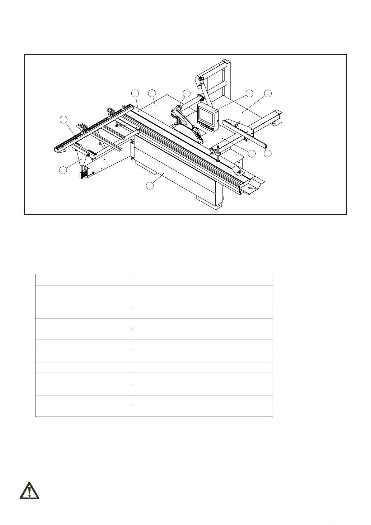
3.1 MAIN COMPONENTS
2
1
1 - Sliding carriage assembly
2 - Cross cutting fence assembly
3 - Sliding table assembly
4 - Rear extension table
5 - Saw blade guard assembly
3.2 TECHNICAL SPECIFICATION
4
10
53
6 - CNC Computer
7 - Right extension table
8 - Rip fence assembly
9 - Main working table
10 - Frame Assembly
6
7
8
9
Motor voltege 415V/50Hz
Main motor power 7.5HP
Scoring motor power 1HP
Main blade diameter 400mm
Scoring blade diameter 120mm
Main saw blade axis diameter 30mm
Scoring blade axis diameter 20mm
Main blade speed 3000/4000/5000rpm
Scoring blade speed 8000rpm
Blade tilt degree
Sliding table cutting stroke 3800mm
Max cutting thickness 125mm
Max cutting width 1500mm
45°~ 90°
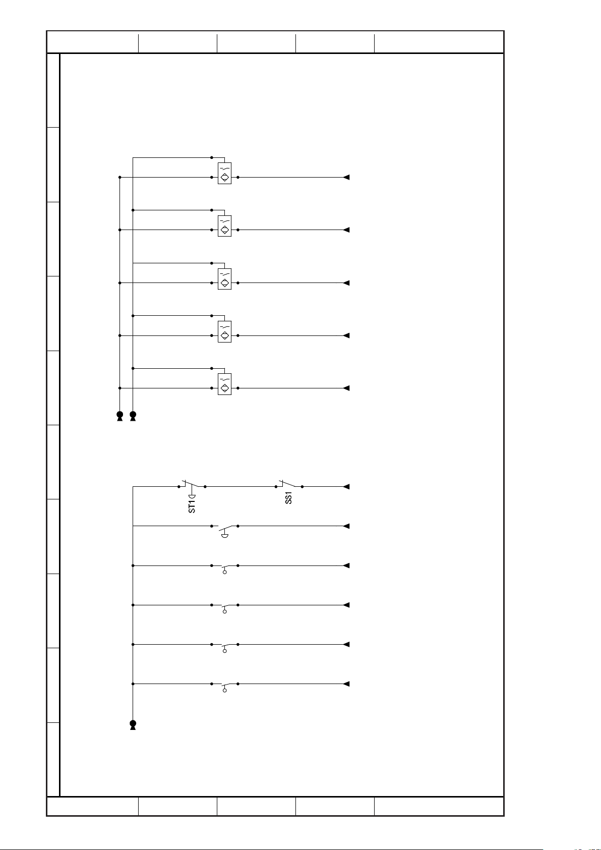
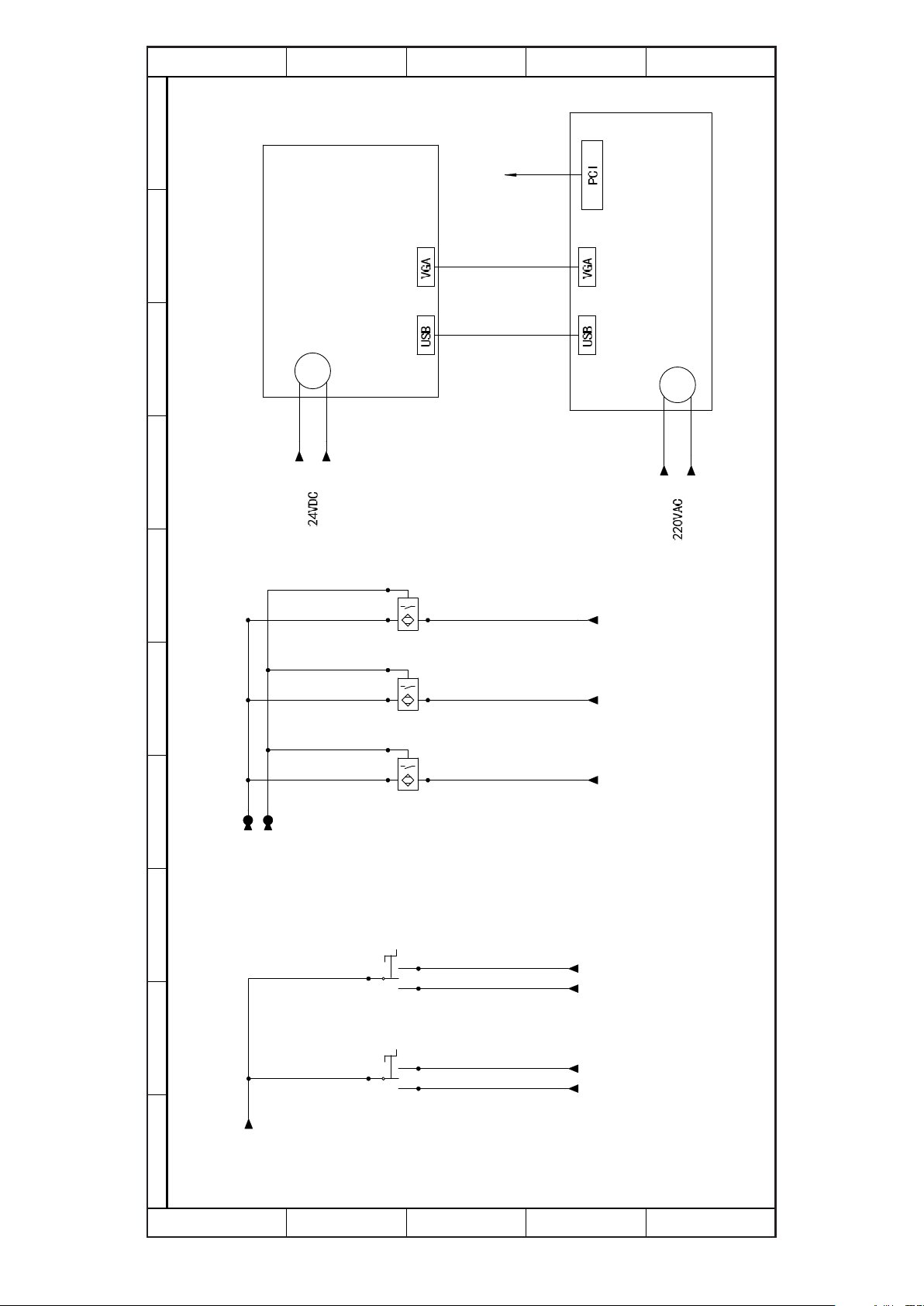
3.3 ELECTRICAL CONNECTION
- Electrical installation should be carried out by competent, qualified personel.
- The mains connection should be made using the terminal box.
- Replacement of the power supply cable should only be done by a qualified electrician
- Connect main leads to a standard 400V ±10% electrical supply which has protection devices of under-voltage, overvoltage, over-current as well as a residual current device(RCD) which maximum residual current rated at 0.03A.
WARNING
For avoiding electric shock or fire, maintenance of electric system should be carried out by
professional staffs and using authorized original accessories.
-6-
U1.1
12345678910
1
2
3
4
5
1
2
3
4
5
KT1
KT1
KM2
KM1T
KS1
KM1L
KM1T
KM1S
KT1
KM1L
KM1S
KM1T
KT2
KM1L
KT2
KS1
KT3
KT3
KS2
KS1
Q1
SS1
ST1
KM1L
Q2
F2
KM2
KM5 KM6
PB1
PB2
PB3
1
M
1
M
TR1
KM6
M5
M4
KM5
1
M
U3
V3
W3
M3
3
3
M
QS1
F3
Q1
N
L1L2L3
Q2
KM2
KM1L
KM1T
W2
U2
KM1S
V2
KS1
M2
M
F1
G2
M1
A+
A- B+ B-
AC1 AC2 AC1 AC2
A+
A- B+ B-
4
5
7
2 3
1
0
08
07
U V W CN2 CN1
R S T L1 L2
75V
0V
75V
0V
75V
0V
12
42
51
16
10
17
18
23
43
11
40
21
19
22
20
25
24
52
15
14
41
0
1
24V
13
1L1
1L3
1L2
W1.2
W1.1
V1.1
U1.2
V1.2
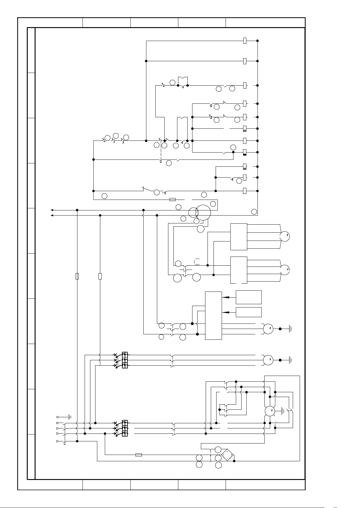
Servo motor actuator
Lifting actuator
Tilting actuator
Lifting motor
Tilting motor
KS2
control line
coder
02-1
02-1
Connect ed to
motion controller
1A+
1A-
1B+
1B-
2A+
2A- 2B+
2B-
Main circuit diagram
-7-
CN5
12345678910
1
2
3
4
5
1
2
3
4
5
04-7
04-7
0
1
AB
+-
24V
-G1
24V
0V
-N1
24V
0V
0V
24V
04-7
01-6
01-6
03-6
04-1
04-7
04-4
03-2
03-6
04-1
04-2
04-2
04-2
04-2
04-4
04-5
04-6
03-5
03-8
03-6
03-2
03-3
03-7
03-7
03-3
03-4
03-4
CN13 CN12
HOME0 LIM3+ LIM3-HOME1 LIM0+ LIM0- LIM1+ LIM1- LIM2+ LIM2- EXI0
EXI15EXI14EXI13EXI12EXI11EXI10EXI8 EXI9
OVCC OGND
A+
A-
B+
B-
AC1
AC2
-GF2
PUL+
PUL-
DIR+
DIR-
EN+
EN-
A+
A-
B+
B-
AC1
AC2
-GF1
PUL+
PUL-
DIR+
DIR-
EN+
EN-
39221123
39221123
PUL+
PUL-
DIR+
DIR-
EN+
EN+
DIR-
DIR+
PUL-
PUL+
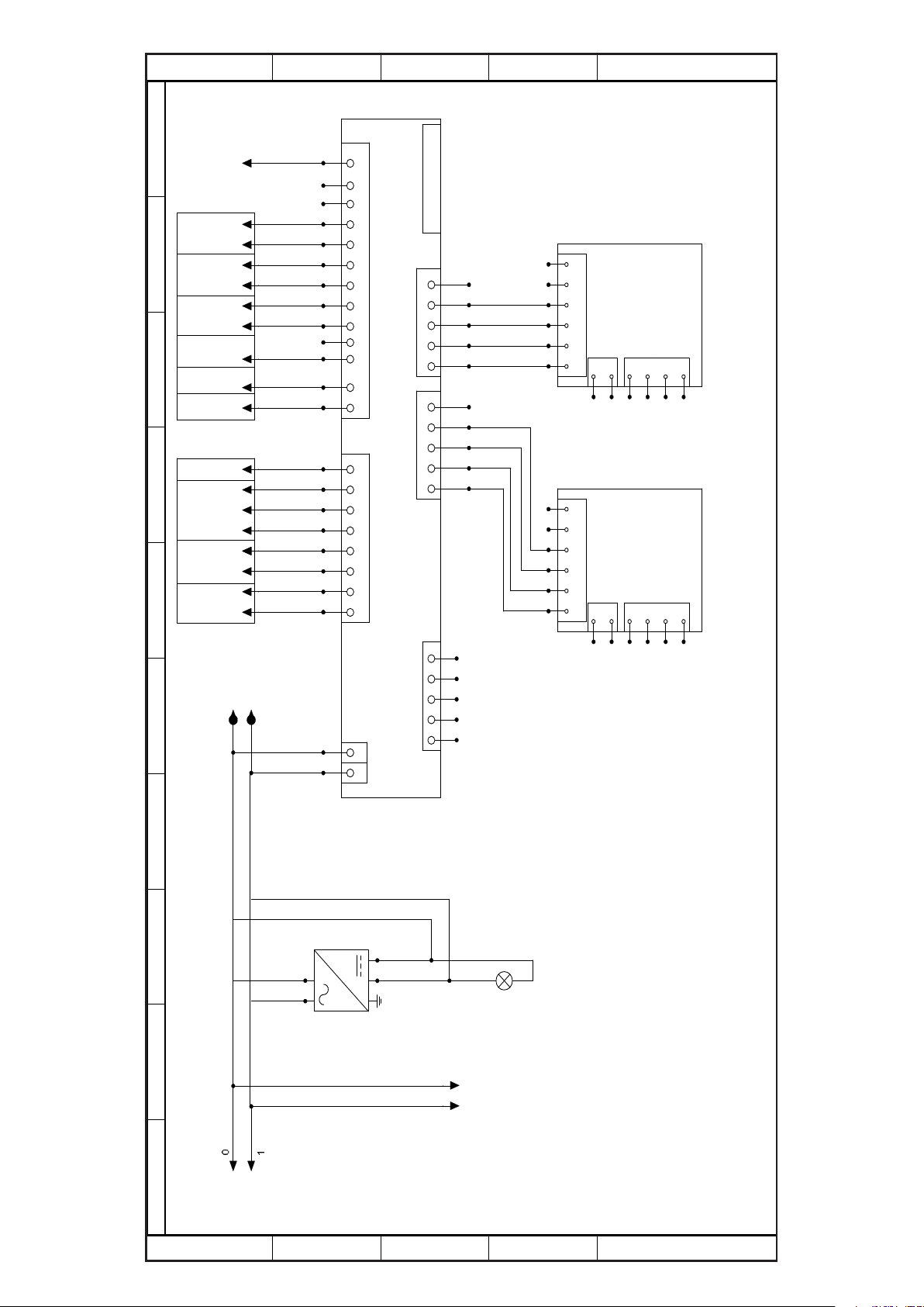
Motion control card
Connected with Seroo actuator
Power
Motor wire
Coder
Actuator for lifting
Motor wire
Coder
Power
Actuator for tilting
Connected with CNC computer
HL1
CN6
CN7
CN1
NEXT
03-9
HOME2 HOME3
Lift
signal
Digital signal
Tilting
signal
scram
Tilting
zero
Lifting
zero
Rip fence
limita tion
Lifting
limitation
Tilting
limitation
Rip fence
zero
Stepper motor motion controller
-8-
12345678910
1
2
3
4
02-8
Tilting zero point
02-8
01-8
Rip fence minus limit
01-8
5
Lifting zero point
Rip fence plus limit
02-8
-B1 -B2 -B3-S17 -B4 -B5
02-5
02-502-5
Rip fence zero point
02-7
Scram
02-10
Next step
02-9
Tilting right limit
02-9
Tilting left limit
02-9
Motion controller signal
Lower limit
0V
0V
-S11 -S12 -S13 -S14
1
2
3
-9-
02-8
Upper limit
4
5
12345678910
1
2
3
Connected to
movement controller
4
5
Touch screen
Power
supply
02-5
02-5
I1
I2
02-7
02-7
Power
02-2
CNC Computer
supply
02-2
02-5
02-5
02-5
0V
0V
-B1 -B2 -B3
I4
I5
-S15 -S16
I7I7
I3
I4
I5
I6 I6
Digital readout signal
02-7
02-6
02-6
Tilting button
02-6
02-6
Manual Photoelectric Computer
Lifting button
1
2
-10-
3
4
5
A
B
3.4 NOISE LEVEL
No load Load
Sound Pressure Level < 80.4dB(A) < 85.7dB(A)
Sound Power Level < 98.1dB(A) < 100.7dB(A)
Associated uncertainty K=4dB
Measurement made in accordance with EN ISO 3746:1995 and EN ISO 11202:1995
The noise levels measured are emission levels and not necessarily the safe working level. Although there is a
correlation between the emission levels and the exposure levels, this cannot be used reliably to determine whether or
not further precautions are required. The factors which affect the actual level of operator exposure include the duration
of exposure, the ambient characteristics and other sources of emission, for example, the number of machines and
other adjacent machining. The permitted exposure values may also vary from country to country. Nevertheless, this
information allows the user of the machine to better evaluate the dangers and risks.
Other factors which reduce exposure to noise are:
- correct tool choice
- tool and machine maintenance
- use of hearing protection systems (e.g. headsets, earplugs,...)
WARNING
Please always use the hearing protection systems if the noise level is over 95dB(A).
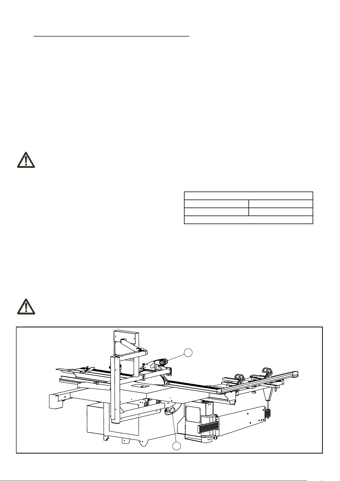
3.5 DUST EXTRACTION
Proper suction eliminates the risks of dust inhalation and
aids better functioning of the machine. The tables list the
minimum air flow and speed values referenced to each
single suction operation.The related pressure drop at the
dust port is 530Pa.
Ensure that the suction system guarantees these values at the hood-houth connection point. (3.5)
Suction mouth diameter:
A - Blade guard ...... ø80 mm
B - Body dust suction ...... ø100 mm
Connect the mouths to the suction system with flexible tubes of adequate diameter. Tighten with clamps. The tube must
be positioned in such a way so as not to obstruct the operator during machining.
Always work with the suction system on. Always start the suction system and the machine at the
WARNING
same time.
Upper hood Lower hood
Air flow 140 cu.m/h 690 cu.m/h
Minimum air speed 20 m/s
Saw
3.5
-11-
4. INSTALLATION
CAUTION
Assembly need to be done by an experienced and trained person.
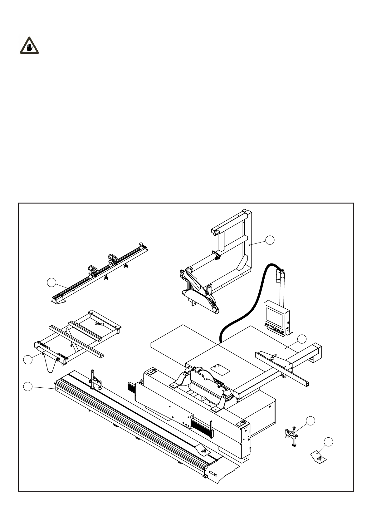
4.1 PACKAGE
- The machine is supplied partly assembled. Prior to use, further assembly is required
- When unpacking the machine the following components are included for the initial assembly
- If any parts are missing, do not attempt to assemble the machine; plug the power cord, or turn the switch off until the
missing parts are obtained and properly installed.
2 cartons:
First carton
1- Sliding table assmebly
Second carton
2- Sliding carriage assembly
3- Cross cutting fence assembly
4- CNC computer assembly
5- Frame assembly
6- Eccentric locking assebmly
7- Clamp assembly
4
3
5
2
1
6
4.1
-12-
7
 Loading...