

TOUGHCUT Diamond 400 Instruction Manual

/RIGINAL¬)NSTRUCTION¬-ANUAL
6ERSION¬
&EBRUARY¬
7OODWORKING¬-ACHINES¬¬!CCESSORIES
4ELEPHONE¬¬¬
&AX¬¬¬
3TARTRITE
5NIT¬"¬!DELPHI¬7AY
3TAVELEY¬¬3¬,3
%MAIL¬SALES RECORDPOWERCOUK
WWWSTARTRITECOUK
%¬%¬¬%¬¬¬
)NDUSTRIAL¬¬
"ANDSAW
)-0/24!.4
&OR¬YOUR¬SAFETY¬READ¬INSTRUCTIONS¬CAREFULLY¬BEFORE¬
ASSEMBLING¬OR¬USING¬THIS¬PRODUCT¬3AVE¬THIS¬
MANUAL¬FOR¬FUTURE¬REFERENCE
PANEL SAW
Diamond 400
Instruction
Manual
IMPORTANT
For your safety, read
instructions carefully
before assembling or
using this product.
Save this manual for
future reference.
Original Instruction
V.1-201810
(%!,4(¬!.$¬3!&%49¬'5)$%,).%3
!LWAYS¬FOLLOW¬THE¬INSTRUCTIONS¬PROVIDED¬WITH¬THE¬MANUAL¬!LWAYS¬WEAR¬SAFETY¬GLASSES¬WHEN¬USING¬WOODWORKING¬
EQUIPMENT¬!LWAYS¬DISCONNECT¬THE¬POWER¬BEFORE¬ADJUSTING¬ANY¬EQUIPMENT¬&AILURE¬TO¬OBSERVE¬PROPER¬SAFETY¬
PROCEDURES¬AND¬GUIDELINES¬CAN¬RESULT¬IN¬SERIOUS¬INJURY
7!2.).'¬$O¬NOT¬ALLOW¬FAMILIARITY¬GAINED¬FROM¬FREQUENT¬USE¬OF¬YOUR¬MACHINE¬AND¬ACCESSORIES¬TO¬BECOME¬
COMMONPLACE¬!LWAYS¬REMEMBER¬THAT¬A¬CARELESS¬FRACTION¬OF¬A¬SECOND¬IS¬SUFlCIENT¬TO¬INmICT¬SEVERE¬INJURY
!LWAYS¬WEAR¬SAFETY¬GLASSES¬WHEN¬
USING¬WOODWORKING¬EQUIPMENT
!LWAYS¬READ¬THE¬INSTRUCTIONS¬
PROVIDED¬BEFORE¬USING¬
WOODWORKING¬EQUIPMENT

INDEX
1 GENERAL INFORMATION
1.1 FOREWORD
1.2 MACHINE IDENTIFICATION
1.3 CUSTOMER SERVICE RECOMMENDATIONS
2 SAFETY PRECAUTIONS
2.1 SAFETY REGULATIONS
2.2 RESIDUAL RISKS
2.3 SAFETY AND INFORMATION SIGNALS
3 SPECIFICATIONS
3.1 MAIN COMPONENTS
3.2 TECHNICAL SPECIFICATION
3.3 ELECTRICAL CONNECTION
3.4 NOISE LEVEL
3.5 DUST EXTRACTION
3.6 SAFETY DEVICES
4 INSTALLATION
4.1 CONTENTS OF PACKAGE
4.2 LIFTING AND UNLOADING
4.3 INSTALLATION ZONE CHARACTERISTIC
4.4 INSTALL OF LOOSE PARTS - INTRODUCTION
5 ADJUSTMENT
5.1 SCORER ADJUSTMENT
5.2 EXTENSION TABLE FLATNESS ADJUSTMENT
5.3 RIP FENCE PRECISION ADJUSTMENT
6 OPERATING PROCEDURES
6.1 MACHINE START AND STOP
6.2 WORKING STATION
6.3 WORKING WITH THE MACHINE
6.4 CORRECT USE FOR THIS MACHINE
7 MAINTENANCE
7.1 REPACE SAW BLADE
7.2 OVERALL CLEANING
7.3 GENERAL LUBRICATION
7.4 REPLACEMENT AND DISPOSAL
8 TROUBLE SHOOTING
9 DIAGRAMS AND COMPONENTS
-2-

1. GENERAL INFORMATION
1.1 FOREWORD
This machine is desinged to make straight and angle cut for wood material, especially for wood board cutting.
Some information and illustrations in this manual may difer from the machine in your possession, since all the
configurations inherent in the machine complete with all the optionals are described and illustrated. Therefore, refer only
to that information strictly connected with the machine configuration you have purchased.
With this manual we would like to provide the necessary information for maintenance and proper use of the machine.
The distribution network is at your service for any technical problem, spare parts or any new requirement you may have
for the development of your activity.
This manual must be read and understood before operating the machine. This will provde a better working knowledge of
the machine, for increased safety and to obtain the best results.
To facilitate its reading, the manual has been divided into sections pointing out the most important operations. For a
quick research of the topics, it is recommended to consult the index. To better stress the importance of some basic
passages, they have been marked by some preceding symbols:
WARNING
CAUTION
Indicates imminent risks which may cause serious injury to the operator or other persons. Be
careful and scrupulously follow the instructions.
A statement advising of the need to take care lest serious consequences result in harm to
material items such as the asset or the product.
1.2 MACHINE IDENTIFICATION
There is a identification plate fixed to the machine, containing the manufacturer's data, year of construction, serial
number and technical specifications.
1.3 CUSTOMER SERVICE RECOMMENDATIONS
Apply the machine to skilled and authorized technical staff to carry out any operation dealing with parts disassembly.
Keep to the instructions contained in this manual for the correct use of the machine.
Only skilled and authorized staff shall use and service the machine after reading this manual.
Respect the accident prevention regulations and the general safety and industrial medicine rules.
CAUTION
-3-

2. SAFETY PRECAUTIONS
2.1 SAFETY REGULATIONS
Read carefully the operation and maintenance manual before starting, using, servicing and
carrying out any other operation on the machine.
The manufacturer disclaims all responsibilities for damages to persons or things, which might be caused by any failure
to comply with the safety regulations.
- The machine operator shall have all necessary prerequisites in oder to operate a complex machiery.
- It is prohibited to use the machine when under the influence of alcohol, drugs or medication.
- All the operators must be suitably trained for use, adjustment and operation of the machine.
- The operators must carefully read the manual paying particular attention to the warning and safety notes. Furthermore,
they must be informed on the dangers associated with use of the machine and the precautions to be taken, and must
be instructed to periodically inspect the guards and safety devices.
- Before carrying out adjustment, repair or cleaning work, disconnect the machine from the electric power by setting the
main switch to stop.
- After an initial bedding-in period or many hours of operation, the driving belts may slacken; this causes an increase in
the tool stopping time (the stopping time must be less than 10 seconds). Immediately tighten them.
- The working area around the machine must be kept always clean and clear, in order to have an immediate and easy
access to the switchboard.
- Never insert materials which are different from those which are prescribed for the machine utilization. The material to
be machined must not contain any metal parts.
- Never machine pieces which may be too small or too wide ithrespect to the machine capacity.
- Do not work wood which has evident defects (cracks, knots, metal parts, etc.)
- Never place hands among the moving parts and/or materials.
- Keep hands clear from the tool; feed the piece with the aid of a pusher.
- Keep the tools tidy and far away from those not authorized persons.
- Never employ cracked nor uckled, neither not correctlyreground tools.
- Never use the tools beyond the speed limit recommended bythe producers.
- Carefully clean the rest surfaces of tools and make surethat they find perfectly horizontally positioned, and with no
dents at all.
- Always wear gauntlets when handling the tools.
- Mount the tools in the right machining direction.
- Never start the machine before having correctly installed all the protections.
- Connect the dust suction hoods to an adequate suction system; suction must always be activated when the machine is
switched on.
- Never open doors or protections when the machine or the system is operating.
- Many unpleasant experiences have shown that anybody may wear objects which could cause serious accidents.
Therefore, before starting working, take any bracelet, watch or ring off.
- Button the working garment sleeve well around the wrists.
- Take any garment off which, by hanging out, may get tangled in the MOVING UNITS.
- Always wear strong working footwear, as prescribed by the accident-prevention regulations of all countries.
- Use protection glasses. Use appropriate hearing protection systems (headsets, earplugs, etc.) and dust protection
masks.
- Never let unauthorized people repair, service or operate the machine.
- The manufacturer is not responsible for any damage deriving from arbitrary modifications made to the machine.
- Any transport, assembly and dismantling is to be made only by trained staff, who shall have specific skill for the
specified operation.
- The operator must never leave the machine unattended during operation.
- During any working cycle break, switch the machine off.
- In case of long working cycle breaks, disconnect the general power supply.
- The operating method to be followed in the event of accident or breakdown, the machine should be turned off
immediately and unplug from main power and ask for assistance for the authorized people. If a blockage is likely to
occur, the workpiece should be move back a little and enable the equipment to be safely unblocked.
WARNING
-4-

2.2 RESIDUAL RISKS
Despite observance of all the safety regulations, and use according to the rules described in this manual, residual risks
may still be present, among which the most recurring are:
- contact with tool
- contact with moving parts (belts, pulleys, etc..)
- recoil of the piece or part of it
- accidents due to wood splinters or fragments
- tool insert ejection
- electrocution from contact with live parts
- danger due to incorrect tool installation
- inverse tool rotation due to incorrect electrical connection
- danger due to dust inhalation in case of working without vacuum cleaner.
Bear in mind that the use of any machine tool carries risks.
Use the appropriate care and concentration for any type of machining (also the most simple).
The highest safety is in your hands.
2.3 SAFETY AND INFORMATION SIGNALS
This signals may be applied on the machine; in some cases they indicate possible danger conditions, in others they
serve as indication.
Always take the utmost care.
SAFETY SIGNALS:
Risk of eye injury. Wear eye protection.
Wear hearing protection systems.
Danger of electric shock. Do not access the area when the machine is powered.
Carefully read and understand the manual before using the machine.
INFORMATION SIGNALS:
Indicate the technical characteristics, direction of rotation and inclination, block and release, etc.
Carefully following the directions to simply the use and adjustment of the machine.
The signals are graphically described and do not require further explanation.
-5-
3. SPECIFICATIONS
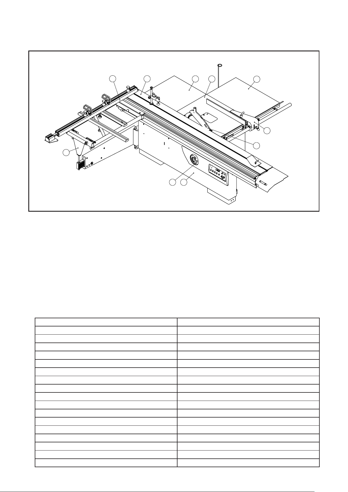
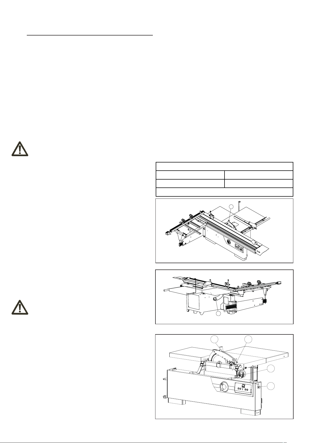
3.1 MAIN COMPONENTS
2
1
1 - Outrigger
2 - Telescopic fence
3 - Sliding table
4 - Rear extension table
5 - Main table
3
10
4
5
9
6 - Right extension table
7 - Rip fence assembly
8 - Blade guard assembly
9 - Frame
10 - lifting ssembly
6
7
8
3.2 TECHNICAL SPECIFICATION
Motor voltage
Main motor power 7.5HP
Pre-cutting motor power 1HP
Main blade diameter 400mm
Scoring blade diameter 120mm
Main blade speed 3000/4000/5000rpm
Scoring blade diameter 8000rpm
Blade tilt degree 0-45°
Max cut depth of main blade
Max cut depth of scoring blade 4mm
Main table size 1020x690mm
Right extension table size
Rear extension table size 750x690mm
Table height to floor
Max.rip capacity
Sliding table cutting stroke
Sliding table size
Outrigger size 1200x630mm
415V/50Hz
125mm@90°;85mm@45°
1020x930mm
900mm
1500mm
3800mm
400x3200mm
-6-
RT18-32-6A-2P
Fuse
F1
3TS32100XB0
Control transformer
3TS32010XB0
KM1T
BK-50-230V-24V
Triangle running contactor
KM1L
LA39-B2-01-r
SS
ST1
Start button
LA42
PB1/PB3
Stop button
Safe switch
QKS7
PB2/PB4
Emergency button
LA39-B2-10-g
BK
Main contactor
Fuse
RT18-32-6A-1P
F2/F3
KM1S
Star start contactor
3TS31010XB0
KM2
Scoring motor contactor
3TS30100XB0
KS1/KS2
Brake control contactor
3TS32010XB0
ST3PF
KT2
Time relay for brake
H3Y-2-24V
KT1/KT3
Time relay
JXPS1602117001B
电气原理图-400V50HZ
设 计
审 核
标准化
校 对
圣焕宝
于健
赵俊义
2018/2/2
2018/1/30
2018/1/30
工 艺
批 准
赵学勇
周喜进
张敏
2018/2/5
2018/2/2
2018/2/2
数 量
重 量
比 例
1:1
修 改 内 容
更改文件号
修改日期
修改人
版次
CAXA
共1页 第1页
青岛金岭电器有限公司
RevA
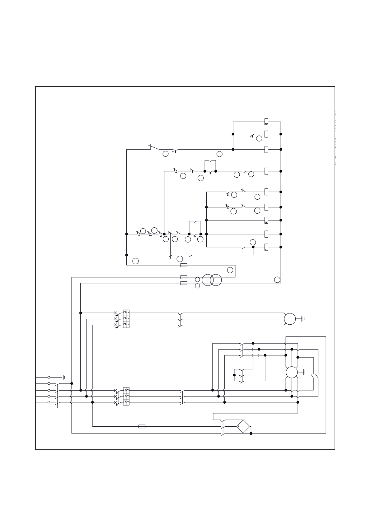
3.3 ELECTRICAL CONNECTION
- Electrical installation should be carried out by competent, qualified personnel.
- The mains connection should be made using the terminal box.
- Replacement of the power supply cable should only be dnoe by a qualified electrician.
- Connect the main leads to a standard 400V±10% electrical supply which has protection devices of under-voltage, over-voltage,
over-current as well as a residual current device (RDC) which maximum residual current rated at 0.03A,the main connection
must have maximum 16A timlag fuse. The test specified in 18.2 of EN 60204-1:2006 should be performed by end user after final
installation.
MANUAL
KT3
KM1L
41
KT2
Q2
26
PB3
KM1L
23
KM2
PB4
42
KT1
KT1
19
20
24
KM1T
KM1S
KM1T
KT3
25
22
21
43
KS2
KS1
KM2
KM1T
KM1S
KT1
15
14
Q1
SS
ST1
16
10
KS1
17
PB2
18
KM1L
40
KM1L
KT2
24V
13
PB1
51
F2
KS1
12
11
1 0
F1
BK
处数
标记
1L31L21L1
W2
V2
M2
U2
KM2
KM1T
PE
N
T
S
R
N
L3
1L3
L2
L1
Q1 Q2
1L1 1L2
KM1L
QS1
F3
2 3
KS2
KM1S
7
5
4
+
-
U1.2
W1.1
V1.2
M1
V1.1
W1.2
KS1
U1.1
-7-

MANUAL
Code
Q1
Q2
F1
F2/F3
KM1L
KM1T
KM1S
KS1/KS2
KM2
KT1/KT3
KT2
BK
ST1
Type
DZ108-20-20A-3P
DZ108-20-2D5A-3P
RT18-32-6A-2P
RT18-32-6A-1P
3TS32100XB0
3TS32010XB0
3TS31010XB0
3TS32010XB0
3TS30100XB0
H3Y-2-24V
ST3PF
BK-50-230V-24V
LA42
Description
Main motor protector
Scoring motor protector
Fuse
Fuse
Main contactor
Triangle running contactor
Star start contactor
Brake control contactor
Scoring motor contactor
Time relay
Time relay for brake
Control transformer
Emergency button
SS
PB1/PB3
PB2/PB4
QKS7
LA39-B2-01-r
LA39-B2-10-g
Safe switch
Stop button
Start button
-8-
Fuse
Scoring motor protector
F2/F3
RT18-32-6A-2P
Star start contactor
KM2
F1
Triangle running contactor
3TS30100XB0
KM1T
Brake control contactor
ST3PF
Time relay for brake
KT1/KT3
Main contactor
DZ108-20-2D5A-3P
RT18-32-6A-1P
Q2
KM1S
3TS31010XB0
Fuse
KM1L
Scoring motor contactor
3TS32100XB0
KS1/KS2
3TS32010XB0
3TS32010XB0
KT2
H3Y-2-24V
Time relay
Start button
Safe switch
LA39-B2-10-g
LA42
Emergency button
Stop button
PB1/PB3SSPB2/PB4
ST1
QKS7
LA39-B2-01-r
PB5
Lift button
M22-WK3-K20
Lift motor contactor
KM3S/KM3D
3TS32010XB0
1L3
F3
1L1 1L2
KM2
KM1L
KS2
KM1T
2 3
4
5
7
W2
U2
V2
KS1
+
-
M2
PE
QS1
L1 L2 L3
N
Q1 Q2
KM1S
U1.1
M1
V1.2
U1.2
W1.2
V1.1
W1.1
16
10
17
18
40
21
22
19
20
24
25
Q1
14
15
KM1L
PB2
KT2
KT1
KT1
KM2
KM1T
KS1
KM1L
KM1T
KM1S
KT1
KM1L
KM1S
KM1T
F2
13
51
12
1 0
11
PB1
KS1
24V
BK
KM2
PB4
PB3
Q2
26
23
F1
04
05
03
KM3S
KM3D
M3
V2
U2
Z2
KT3
42
43
KM1L
KT2
KS1
KT3
KS2
41
27
31
30
PB5
KM3D
KM3S
FC1 FC2
KM3S
KM3D
SS
ST1
L2
N
L3L1
1L31L1 1L2
32
29
28
JXPS1602117001C
电气原理图-400V50HZ
标记
处数
设 计
审 核
标准化
校 对
圣焕宝
于健
赵俊义
2018/2/2
2018/1/30
2018/1/30
工 艺
批 准
赵学勇
周喜进
张敏
2018/2/5
2018/2/2
2018/2/2
数 量
重 量
比 例
1:1
修 改 内 容
更改文件号
修改日期
修改人
版次
CAXA
共1页 第1页
青岛金岭电器有限公司
RevA
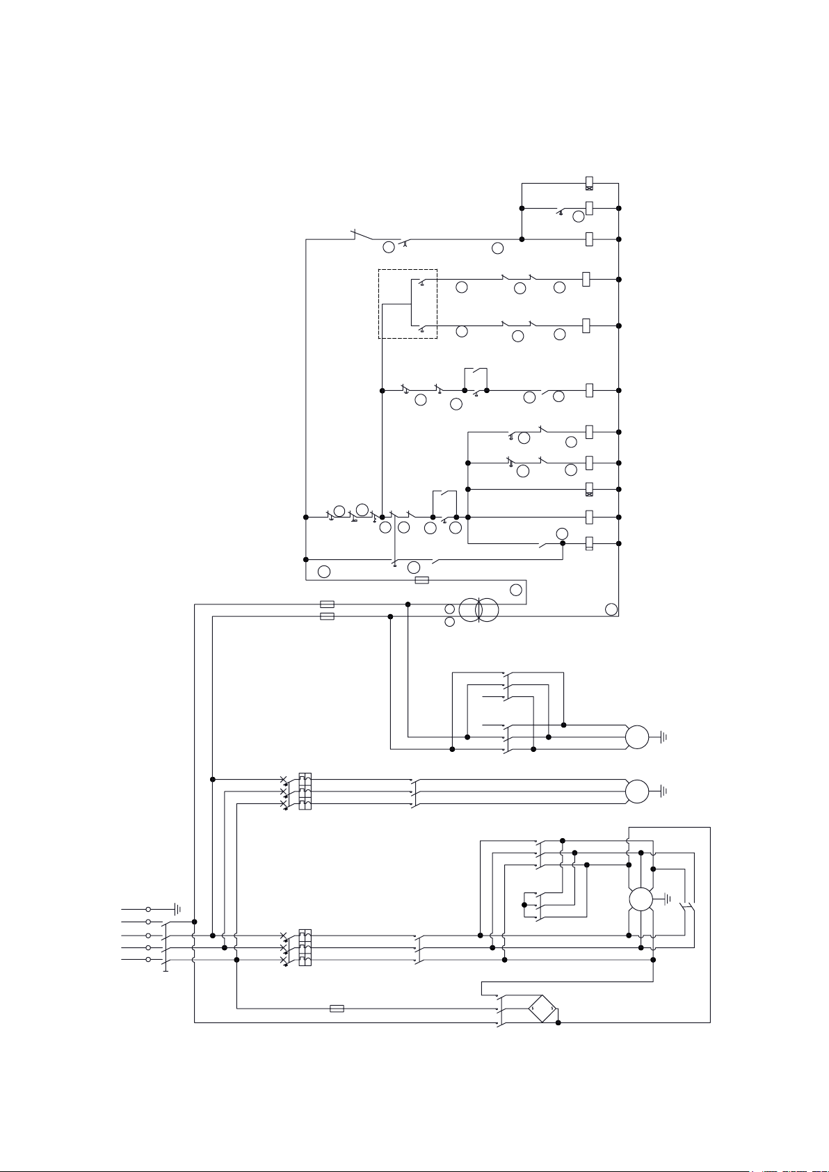
SEMI-AUTOMATIC
-9-

SEMI-AUTOMATIC
Q1
Q2
F1
F2/F3
KM1L
KM1T
KM1S
KS1/KS2
KM2
KT1/KT3
KT2
Type
DZ108-20-20A-3P
DZ108-20-2D5A-3P
RT18-32-6A-2P
RT18-32-6A-1P
3TS32100XB0
3TS32010XB0
3TS31010XB0
3TS32010XB0
3TS30100XB0
H3Y-2-24V
ST3PF
Description
Main motor protector
Scoring motor protector
Fuse
Fuse
Main contactor
Triangle running contactor
Star start contactor
Brake control contactor
Scoring motor contactor
Time relay
Time relay for brake
CodeCode
BK
ST1
SS
PB1/PB3
PB2/PB4
PB5
KM3S/KM3D
Type
BK-50-230V-24V
LA42
QKS7
LA39-B2-01-r
LA39-B2-10-g
M22-WK3-K20
3TS32010XB0
Description
Control transformer
Emergency button
Safe switch
Stop button
Start button
Lift button
Lift motor contactor
-10-
Fuse
Scoring motor protector
F2/F3
RT18-32-6A-2P
Star start contactor
KM2
F1
Triangle running contactor
3TS30100XB0
KM1T
Brake control contactor
ST3PF
Time relay for brake
KT1/KT3
Main contactor
DZ108-20-2D5A-3P
RT18-32-6A-1P
Q2
KM1S
3TS31010XB0
Fuse
KM1L
Scoring motor contactor
3TS32100XB0
BK-50-230V-24V
KS1/KS2
3TS32010XB0
3TS32010XB0
KT2
H3Y-2-24V
Q1
BK
Time relay
Start button
Safe switch
LA39-B2-10-g
LA42
Emergency button
Stop button
PB1/PB3SSPB2/PB4
ST1
QKS7
LA39-B2-01-r
PB5
Lift button
M22-WK3-K20
Lift motor contactor
KM3S/KM3D
3TS32010XB0
Deflection motor contactor
KM4S/KM4D
3TS32010XB0
Deflection button
PB6
M22-WK3-K20
1L3
F3
1L1 1L2
KM2
KM1L
KS2
KM1T
2 3
4
5
7
W2
U2
V2
KS1
+
-
M2
PE
QS1
L1 L2 L3
N
Q1 Q2
KM1S
U1.1
M1
V1.2
U1.2
W1.2
V1.1
W1.1
16
10
17
18
40
21
22
19
20
24
25
Q1
14
15
KM1L
PB2
KT2
KT1
KT1
KM2
KM1T
KS1
KM1L
KM1T
KM1S
KT1
KM1L
KM1S
KM1T
F2
13
51
12
1 0
11
PB1
KS1
24V
BK
KM2
PB4
PB3
Q2
26
23
F1
04
05
03
KM3S
KM3D
M3
V2
U2
Z2
KT3
42
43
KM1L
KT2
KS1
KT3
KS2
41
27
31
30
PB5
KM3D
KM3S
FC1 FC2
KM3S
KM3D
SS
ST1
L2
N
L3L1
1L31L1 1L2
32
29
28
KM4S
FC4
33
35
KM4D
KM4D
FC3
37
34
36
38
PB6
KM4S
06
M4
KM4S
U2
08
KM4D
V2
Z2
07
JXPS1602117001D
电气原理图-400V50HZ
标记
处数
设 计
审 核
标准化
校 对
于健
于健
赵俊义
2018/1/30
2018/1/30
2018/1/30
工 艺
批 准
赵学勇
周喜进
张敏
2018/2/1
2018/1/31
2018/1/31
数 量
重 量
比 例
1:1
修 改 内 容
更改文件号
修改日期
修改人
版次
CAXA
共1页 第1页
青岛金岭电器有限公司
RevA
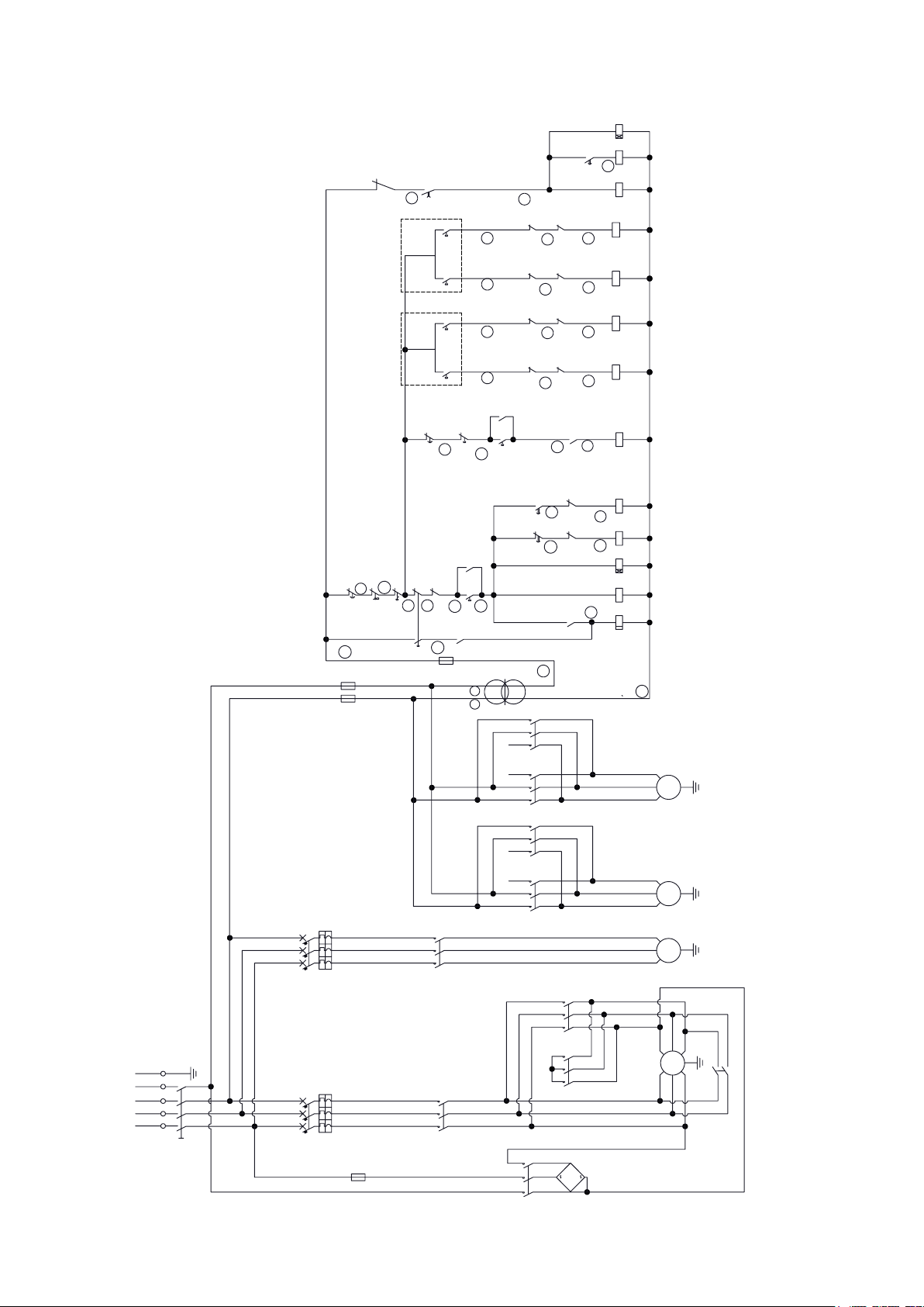
AUTOMATIC
-11-

AUTOMATIC
Q1
Q2
F1
F2/F3
KM1L
KM1T
KM1S
KS1/KS2
KM2
KT1/KT3
KT2
Type
DZ108-20-20A-3P
DZ108-20-2D5A-3P
RT18-32-6A-2P
RT18-32-6A-1P
3TS32100XB0
3TS32010XB0
3TS31010XB0
3TS32010XB0
3TS30100XB0
H3Y-2-24V
ST3PF
Description
Main motor protector
Scoring motor protector
Fuse
Fuse
Main contactor
Triangle running contactor
Star start contactor
Brake control contactor
Scoring motor contactor
Time relay
Time relay for brake
CodeCode
BK
ST1
SS
PB1/PB3
PB2/PB4
PB5
KM3S/KM3D
KM4S/KM4D
PB6
Type
BK-50-230V-24V
LA42
QKS7
LA39-B2-01-r
LA39-B2-10-g
M22-WK3-K20
3TS32010XB0
3TS32010XB0
M22-WK3-K20
Description
Control transformer
Emergency button
Safe switch
Stop button
Start button
Lift button
Lift motor contactor
Deflection motor contactor
Deflection button
-12-
3.4 NOISE LEVEL
C
D
No load Load
Sound Pressure Level < 80.4dB(A) < 85.7dB(A)
Sound Power Level < 98.1dB(A) < 100.7dB(A)
Associated uncertainty K=4dB
Measurement made in accordance with EN ISO 3746:1995 and EN ISO 11202:1995
The noise levels measured are emission levels and not necessarily the safe working level. Although there is a
correlation between the emission levels and the exposure levels, this cannot be used reliably to determine whether or
not further precautions are required. The factors which affect the actual level of operator exposure include the duration
of exposure, the ambient characteristics and other sources of emission, for example, the number of machines and
other adjacent machining. The permitted exposure values may also vary from country to country. Nevertheless, this
information allows the user of the machine to better evaluate the dangers and risks.
Other factors which reduce exposure to noise are:
- correct tool choice
- tool and machine maintenance
- use of hearing protection systems (e.g. headsets, earplugs,...)
WARNING
Please always use the hearing protection systems.
3.5 DUST EXTRACTION
Proper suction eliminates the risks of dust inhalation and
aids better functioning of the machine. The tables list the
minimum air flow and speed values referenced to each
single suction operation.The related pressure drop at the
dust port is 530Pa.
Ensure that the suction system guarantees these values
at the hood-houth connection point. (Fig.3.5)
Suction mouth diameter:
A - Blade guard ...... ø60 mm
B - Body dust suction ...... ø100 mm
Connect the mouths to the suction system with flexible
tubes of adequate diameter. Tighten with clamps. The
tube must be positioned in such a way so as not to
obstruct the operator during machining.
Saw
Upper hood Lower hood
Air flow 140 cu.m/h 690 cu.m/h
Minimum air speed 20 m/s
A
Fig.3.5.1
WARNING
Always work with the suction system on. Always start the
suction system and the machine at the same time.
3.6 SAFETY DEVICES
The machine is equipped with the following safety
devices: (Fig.3.6)
A - Safety Switch.
Stops the machine if the guard D is opened to perform
operations on the blade.
B - Emergency Switch
When the button is pressed, the power will been cut
immediately. It is a mechanical-operated push-button.
Reset this button by turning it clockwise.
C - Saw blade guard
B
Fig.3.5.2
A
B
Fig.3.6
-13-
4. INSTALLATION
4. INSTALLATION
CAUTION
Assembly need to be done by an experienced and trained person.
CAUTION
Assembly need to be done by an experienced and trained person.
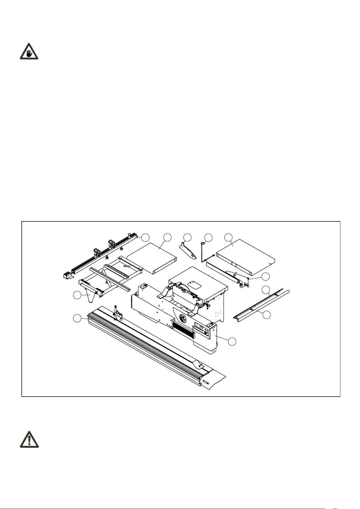
4.1 CONTENTS OF PACKAGE
- The machine is supplied partly assembled. Prior to use, further assembly is required.
- When unpacking the machine the following components are included for the initial assembly.
- If any parts are missing, do not attempt to assemble the machine; plug in the power cord, or turn the switch on until the
missing parts are obtained and properly installed.
Total one carton:
1 - Sliding table assembly
2 - Outrigger assembly
3 - Telescopic fence assembly
4 - Rear extension table
5 - Blade guard assembly
6 - Vacuum tube support seat
7 - Right extension table
8 - Rip fence assembly
9 - Scale bracket
10 - Guide rail
11 - Frame assembly
2
1
3
4
Fig.4.1
5
6
7
8
9
10
11
4.2 LIFTING AND UNLOADING
WARNING
Lifting and handing should only be carried out by skilled personel specially trained to execute this kind of operations.
During loading and unloading, avoid knocks to prevent damages to persons and things. Make sure no one is standing
under the overhung load and/or within the bridge crane working range during machine lifting and handing.
-14-
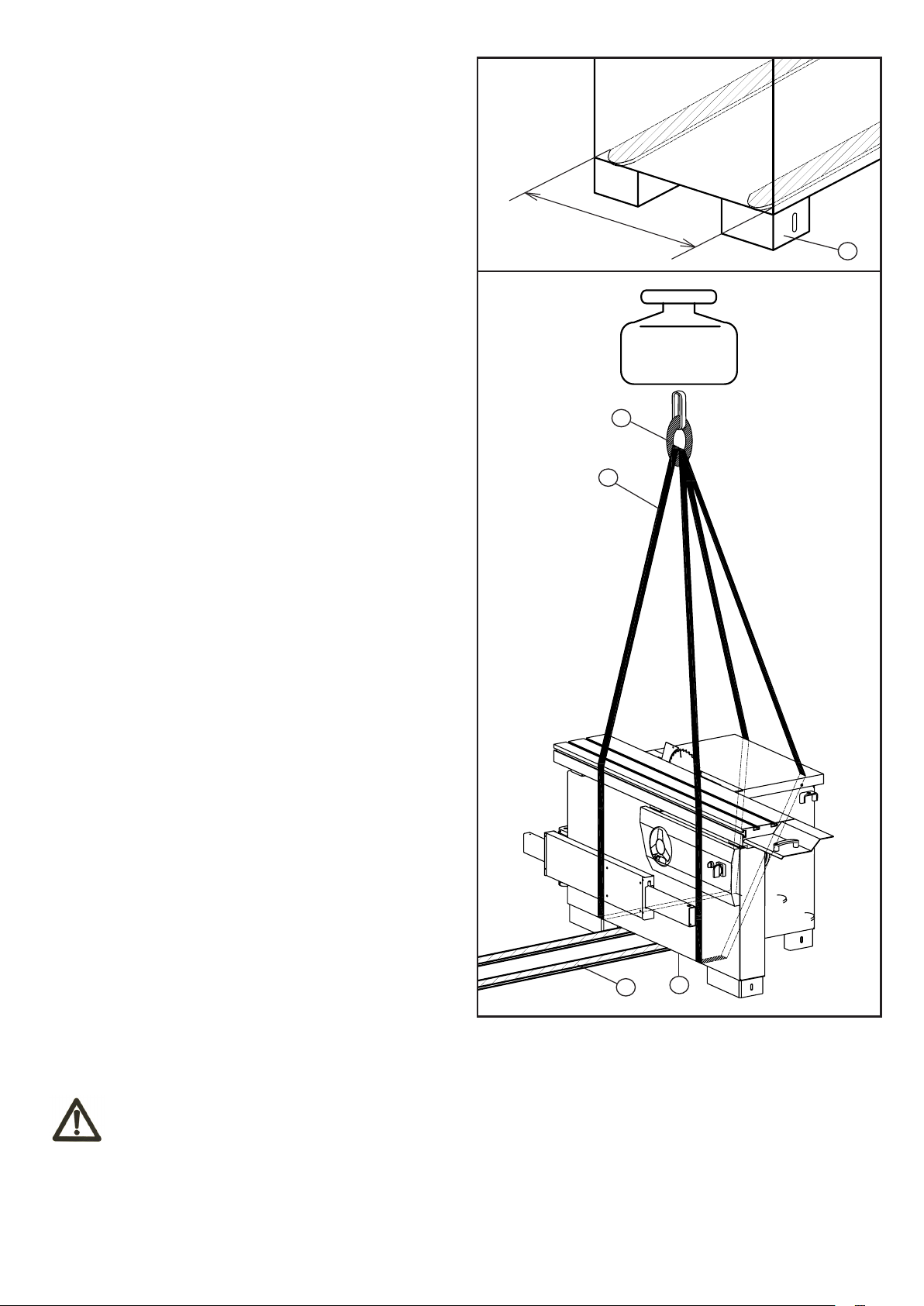
Lifting may be carried out by bridge crane or self-propelled
lift truck. Before starting the manoeuvres, free the machine
of all the parts used for transport or Packaging that have
remained on the machine. Check that the capacity of the
lifting equipment is adequate for the gross weight of the
machine indicated Fig.4.2.
If hoisting is carried out with a lift truck, proceed as
follows:
– adjust the width of the forks A to 550 mm
– Insert forks A as in the figure in correspondence to name
plates E ensuring that these are wedged against the back
of the rear feet D.
If a bridge crane or a crane is available,proceed as
follows:
– provide two slings B of suitable length and capacity
(Belts minimum length 4000mm)
– lift the slings and position them as is shown in the
Fig.4.2
– fasten the slings to the bridge crane C having adequate
lifting power
– move the bridge crane by small steps to allow the slings
B to settle, until optimum stability conditions are reached
– lift carefully and slowly, without causing the load to
swing, and place the machine in the selected setting
– remove the protective wax coat from all tables and
unpainted surfaces, using kerosene or its derivative
products. Do not use any solvent, petrol or gas oil, which
might dull the paint or oxidate machine parts.
550mm
D
1000KGS
C
B
min L=400mm
4.3 INSTALLATION ZONE CHARACTERISTICS
min L=400mm
A
E
Fig.4.2
WARNING
It is prohibited to install the machine in explosive environments.
The installation zone must be selected evaluating the work space required depending on the dimension of the pieces
to be machined,and taking into account that a free space of at least 800 mm must be left around the machine.It is also
necessary to check The floor capacity and its surface, so that the machine base is evenly resting on its four supports.A
power outlet and a chip-suction system connection shall be closeto the selected machine setting and it must be
conveniently lighted (luminous intensity: 500 LUX).
-15-
Fixing to the floor
4.4 INSTALL OF LOOSE PARTS - INTRODUCTION
A few elements will be disassembled from the machine main structure due to packaging and shipping requirements.
These loose parts should be installed as follows.
WARNING
Please tighten all bolts and nuts absolutely. Otherwise, may cause machine wobble or serious injury to the operator or
other persons.
A
B
C
1
2
1
2
4.3 INSTALLATION ZONE CHARACTERISTICS
WARNING
It is prohibited to install the machine in explosive environments.
The installation zone must be selected evaluating the work space required depending on the dimension of the pieces
to be machined,and taking into account that a free space of at least 800 mm must be left around the machine.It is also
necessary to check The floor capacity and its surface, so that the machine base is evenly resting on its four supports.A
power outlet and a chip-suction system connection shall be closeto the selected machine setting and it must be
conveniently lighted (luminous intensity: 500 LUX).
Fig.4.4.1
A
B
C
1
2
1
2
Fig.4.4.3
A
B
C
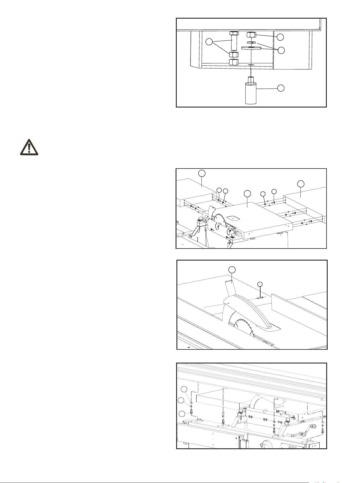
The machine must be fixed to the floor.
- Use bolt/nut A to level the feet to ensure machine is well
located.
- Put expansion bolts D into ground, use washer/lock
wahser C and hex nut B to fasten the bolts.
A
B
C
D
4.4 INSTALL OF LOOSE PARTS - INTRODUCTION
Fig.4.3
A few elements will be disassembled from the machine main structure due to packaging and shipping requirements.
These loose parts should be installed as follows.
WARNING
Please tighten all bolts and nuts absolutely. Otherwise, may cause machine wobble or serious injury to the operator or
other persons.
A
4.4.1 INSTALL EXTENSION TABLE
1
Tools Required for Assembly:
2
C
- Wrench 16mm
- L Wrench 5mm
- Install Rear extension tables A to main table C with bolt
1 and washer 2.
- Install Right extension tables B to main table C with bolt
1 and washer 2.
4.4.2 INSTALL BLADE GUARD
Tools Required for Assembly:
-Wrench 10 mm
Fig.4.4.1
A
1
2
2
B
-Install Blade guard A to Riving knife with part 2.
Fig.4.4.2
4.4.3 INSTALL SLIDING TABLE
- Put the sliding table onto the frame support surface as
shown.
- Lock the sliding table to the frame using part A,B and C,
with 18mm wrench.
-16-
C
B
A
Fig.4.4.3

4.4.4 INSTALL OUTRIGGER
B
- Put the square sliding table C into the slot of sliding
table A.
- Put the support rod D into the hole of square sliding
table C and the hole on support arm E.
- Lock the handle B.
4.4.5 INSTALL TELESCOPIC FENCE
- Insert pin A in front of fence into the hole on assistant
sliding table side, set handle B on pin A and drop lock.
- Insert Pin B in the middle of fence into long slotted hole
on assistant sliding table, set handle C on pin B and drop
lock;
- Lock handle F on assistant sliding table;
- Adjust precise angle between fence and blade through
adjust the extension length of bolt E.
C
D
E
A
Fig.4.4.4
A
B
E
4.4.6 INSTALL FENCE RAIL
Tools Required for Assembly:
- Wrench 18mm
- L Wrench 5mm
- Install scale seat B to tables with screw 1.
- Put the scale A into the slot of scale seat B.
- Install shaft 6 onto the guide rail C, and then mount the
guide rail to tables with part 2, 3, 4, 5, 6 and 7.
4.4.7 INSTALL RIP FENCE
- Install the rip fence seat A to guide rail B as the picture
shown.
- Install the screw C onto the guide rail B.
- Install the rip fence D to the fence seat A along its slot.
F
C
D
Fig.4.4.5
Fig.4.4.6
A
D
C
-17-
B
Fig.4.4.7
 Loading...