

Page 1
A
September 2014
900910-001
Rev 00
PLAYDIUM Operator Test Setup
Installation Guide
Purpose
This document provides information about the Playdium Operator Test Setup (TouchTunes p/n: 600223-001) and shows
how to perform its assembly and installation.
udience
• TouchTunes Playdium Jukebox Operators
• TouchTunes field service and customer support
Estimated Time
30 minutes
Required Personnel
1 Technician
Topics
• Important Safety Information
• Included in This Kit
• Mounting the Chassis
• Installing a Payment Door
• Adjusting the Door Height
• Finishing Up
• Contacting TouchTunes Technical Support
This document includes the following task types:
Software
Electrical
Mechanical
Packaging
Important Safety Information
WARNING: When performing this procedure or any other maintenance on your jukebox, the unit must be powered
off.
IMPORTANT: A properly-grounded anti-static wrist strap should be worn at all times during the procedure
presented below.
Page 2

2 Playdium Operator Test Setup Installation Guide
Included in This Kit
Included in This Kit
Ensure that you have received all the required parts before proceeding with this installation.
Part Amount TouchTunes Part #
Playdium Bare Chassis, with the following pre-installed: 1 401417-001
• Backplane 1 300819-001
• Volume PCB (bottom button board) 1 300188-001
• ID Module 1 401270-002
• Cable, ID Module to Backplane, 11” 1 300885-011
• Cable, Volume PCB to Backplane, 16” 1 300881-016
Accessory Bag, containing:
• Screw, Philips-head, flat, M3x6, zinc-plated 4 200214-006
AC Power Cord, 108” 1 300846-108
Payment Door Damper (includes screw) 1 401235-001
Wall Mounting Template 1 900853-001
This document 1 900910-001
Page 3
Mounting the Chassis
3Playdium Operator Test Setup Installation Guide
Mounting the Chassis
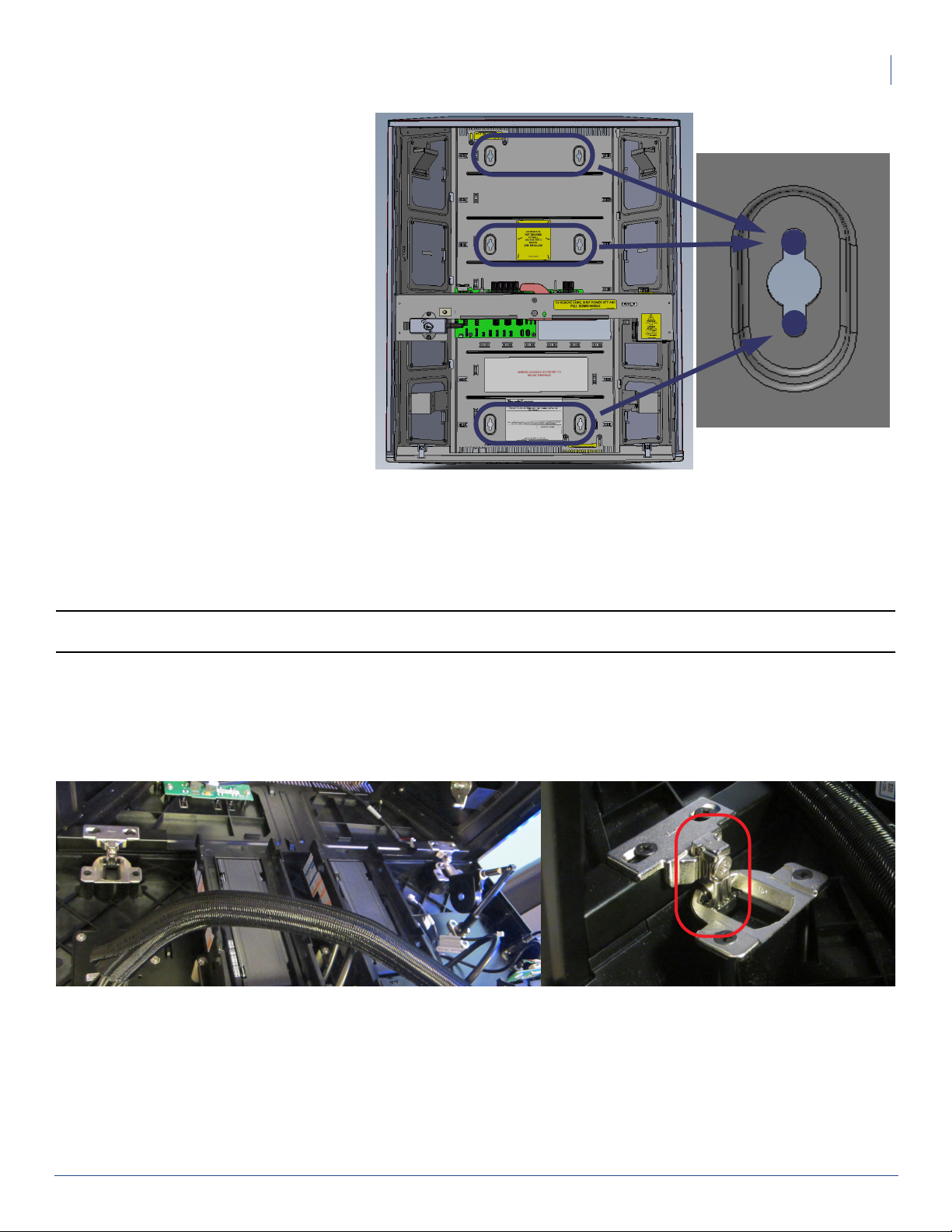
1. Using the included template, mark the
position for the chassis on the wall where
you intend to install the test setup,
ensuring that the template is leveled.
2. Mark where the screws will be inserted.
The top two holes should be aligned with
the top part of the mounting slot in the
chassis, so that the chassis will “hang”
from those two screws, while the bottom
two holes should be aligned with the
bottom of the mounting slots, so as to
better secure the chassis to the wall.
3. Partially install the top two screws on the
markings you just made. You will soon be
hanging the chassis on those two screws.
If installing on drywall or concrete, use
wall anchors designed to support at least
50lbs each, then fasten the chassis to the
wall by inserting the screws through the holes in the chassis, and into the anchors.
4. Hang the chassis on the loosened top two (2) screws.
5. Fasten the chassis to the wall using 4 screws through the middle and bottom holes. For the bottom two (2) screws,
ensure you use the top part of the mounting slots.
6. Tighten the top two (2) screws.
Top
Middle
Bottom
Screw Position
Note: Mounting screws and wall anchors are not provided. The correct type of screw and anchor to use depends on the
material of the surface being used for mounting.
Installing a Payment Door
This section will not provide any details about how to assemble the payment door prior to installing it on the Operator Test
Setup. For more on how to put together a payment door, see the 900908-001 Payment Door FRU document.
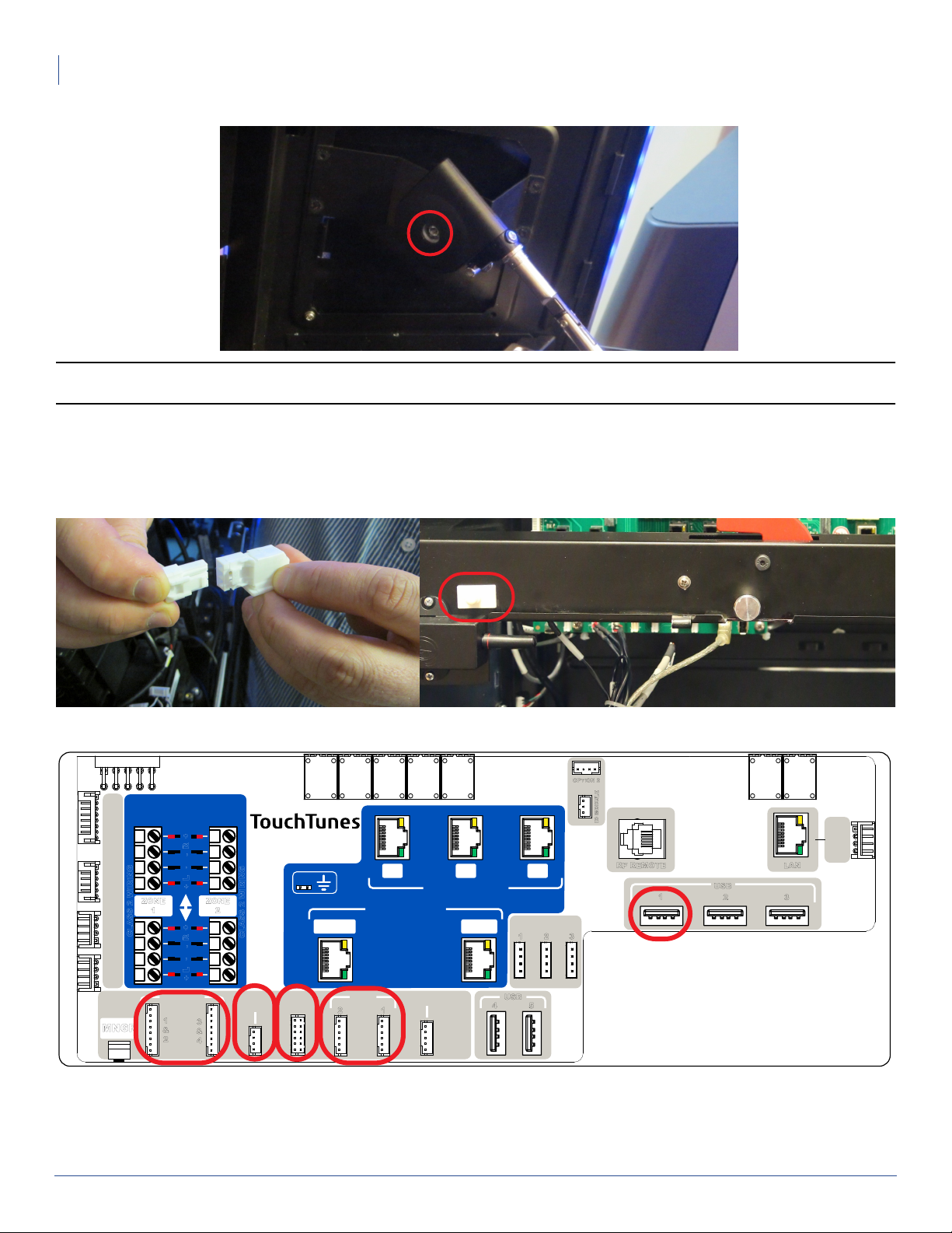
1. Insert the payment door into its hinges.
2. While holding the door and pushing it up slightly to keep the hinges from dropping all the way down, tighten the screw
on each hinge. You may have to readjust the height of the door on the hinges later.
3. If the payment door doesn’t come with its own damper, you may use the one included with the Operator Test Setup.
Insert the smaller end of the damper into its corresponding hole in the door, while holding it turned 90 degrees from its
final orientation. Turn it to the right position so it stays in place on the door.
Page 4
4 Playdium Operator Test Setup Installation Guide
Installing a Payment Door
4. Fasten the round end of the damper to the chassis, using the screw that is included with the damper.
Note: TouchTunes recommends applying Loctite Threadlocker to the screw before fastening the damper to the chassis, if
you will not be removing the door and its damper on a regular basis.
5. Connecting cables:
The cables below will enable various components. Connect them to the backplane as needed.
• Door switch: run the door switch cable through the door switch hole in the middle bar of the chassis, then reconnect
the cable to the switch. Reinsert the switch into position (push until it snaps into place) and finally, connect the cable
to the backplane.
• Payment means backlighting: reconnect to the backplane.
• Credit card reader: reconnect USB to connector USB 1, on the backplane.
OPTION 2
ART900777-001R04
SPEAKERS
RING
I
VOLUME PCB OPTION 2
W
ZONE
ASS 2
CL
SIDE LIGHT
LEFT TOP
MNGR
1
PAYMENT
LIGHT
1
&
2
+
R
-
-
L
+
ZONE
2
+
R
-
-
L
+
3
&
4
CLASS 2 WIRING
DOOR
SWITCH
SPK
MIC 1 AUX
COIN
ACC
2
2 1 3
AUDIO OUT
AUDIO IN
BILL
ACC
SERIAL
1
4
EXT. LIGHT
1
USB
2 3
5
ID MODULE
RF REMOTE
LAN
1
USB
2 3
• Bill acceptor(s): reconnect the cable(s) to the backplane. If you had removed the bill stackers, you can now snap
them back on.
RIGHT
SIDE LIGHT
Page 5
Finishing Up
Finishing Up
1. Install the Airflow Assembly (which can be ordered as a FRU kit, with part number 600208-001.) See 900874-001 Airflow
Assembly FRU Installation guide, or the Playdium Quick Start Guide or the Playdium Installation and Setup Guide for
more on how to install the Airflow Assembly. Playdium should not be turned on without a properly-installed,
connected and functional Airflow Assembly.
2. Reinstall the Core, following the process indicated in the Playdium Quick Start Guide or the Playdium Installation and
Setup Guide.
CAUTION: Do not power up Playdium immediately after installing a core that was brought in from a cold place into a
warm place, as condensation may have occurred on internal components. Wait for the unit to reach room temperature
before using it.
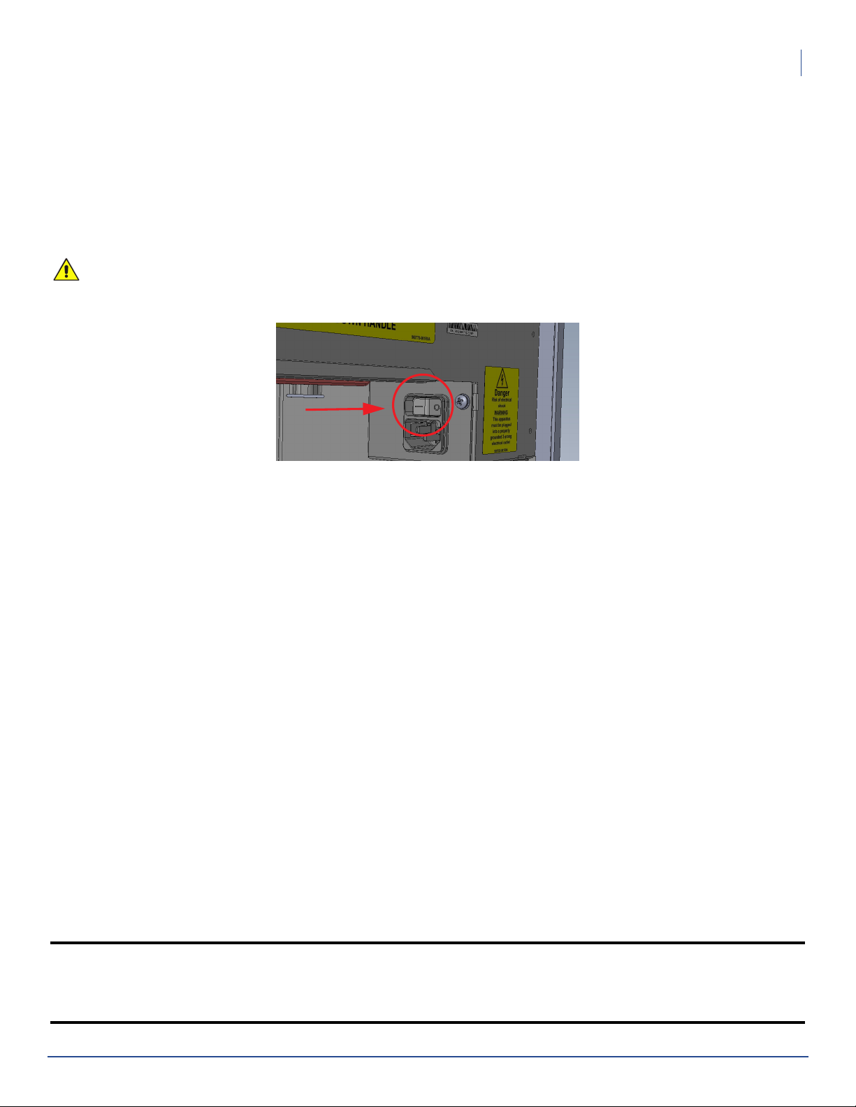
3. Set the power switch on the Playdium’s power strip to ON.
5Playdium Operator Test Setup Installation Guide
4. Close the payment panel by gently pulling it up and shut, then pressing on its front face to engage the locking
mechanism.
5. Secure the payment panel by using the key to lock its case.
Contacting TouchTunes Technical Support
If you need help with or have questions about this document, contact TouchTunes by:
• using the e-mail links on the Contacts page on the TouchTunes Dashboard at
https://operator.touchtunes.com
• calling TouchTunes 24/7 Service Hotline at 847-353-1954
To help us assist you more effectively with problem reports, this information may be required when contacting TouchTunes
Support:
• Jukebox model, such as Playdium, Virtuo, Allegro MX-1, Ovation
• Jukebox ID
• the serial number of any component you believe to be defective
• the date/time of the problem
• actions performed immediately before the problem occurred
• any additional comments
TouchTunes Interactive Networks, Inc.
400 Sainte Croix Avenue, Suite 200 E
Montreal, Quebec,
Canada, H4N 3L4
TouchTunes Interactive Networks, Inc.
850 Third Ave, Suite 15C
New York, NY 10022
USA
Copyright © 2014 TouchTunes Interactive Networks
Technical Support
847-353-1954
www.touchtunes.com
 Loading...