

TouchTunes Maestro II Quick Start Manual
1 of 12
About this guide
This guide explains how to install and activate the Maestro Digital
Jukebox. Maestro is different from conventional jukeboxes, both in the
way it operates and in the way it is installed. It is therefore strongly
recommended that you review this guide thoroughly before you begin.
For detailed information on planning your installation, refer to the Maestro
Operator’s Manual on the TouchTunes web site.
Service and support
For service and support issues, call the TouchTunes 24/7 Service Hotline
at 888-711-5853. You must provide the Jukebox ID number to obtain
service. This number can be found underneath the front of Maestro or
inside to the right of the fan.
Components
Maestro ships in several boxes. If any component appears to be damaged,
do not attempt to use or install the system. Notify TouchTunes or your
local distributor immediately.
Verify that you have received the following components:
Dimensions and weight
Important safety information
Read all safety instructions before installing this product.
Maestro II Jukebox
Quick Start Guide
April 2005
900148-001
Maestro
1 Maestro Digital Jukebox with power line installed
1 Maestro wall bracket
1 Thumbscrew wing nut (on the wall bracket)
1 Parts kit containing:
1 Remote control
1 Remote control mounting bracket
2 AAA batteries
2 Keys (ilco #549)
1 Air filter
1 Female RCA to DIN Adapter, P/N: 300141-012
1 Male RCA to DIN Adapter, P/N: 300143-012
1 Phone cable with RJ11 connectors (7 feet)
1 Terminal connector (four-position Euro-style). Used to
connect an optional microphone.
Hard drive (shipped separately)
Height Width Depth Weight
Crated 48” 28” 14” 80 lbs.
Uncrated 32.5” 19” 8” 60 lbs.
CAUTION: Maestro components are heavy and represent a
serious safety hazard if their mounting system should fail.
Therefore, installation should only be performed by an
experienced installer or licensed contractor that is familiar with
standard rigging, mounting, and hanging practices, as
recognized by a licensed engineer or governmental agency in
your area.
CAUTION: Maestro mounting components are UL listed and
CSA approved only when used as specified in this guide. Any
other use or modification of the mounting components is
expressly prohibited, as this may present an unacceptable risk
of structural failure.
CAUTION: Do not install Maestro near any heat sources, such
as radiators, heat registers, stoves, or other apparatus
(including amplifiers) that produce heat.
CAUTION: Do not defeat the safety purposes of the polarized
or grounding-type plug. A polarized plug has two blades with
one blade wider than the other. A grounding-type plug has two
blades and a third grounding prong. The wider blade or the
third grounding prong are provided for your safety. If the
provided plug does not fit in your outlet, consult an electrician
for replacement of the obsolete outlet.
CAUTION: See product enclosure for safety related markings
and refer to the Maestro Operator’s Manual on the TouchTunes
web site for additional safety information.
CAUTION: Dispose of used batteries in accordance with the
regulations in your area. Do not incinerate.
CAUTION: The lights inside Maestro contain mercury. Disposal
of this material may be regulated in your area due to
environmental considerations. For disposal or recycling
information, please contact your local authorities or the
Electronic Industries Alliance at www.eiae.org.
2 of 12
Important concepts
Wiring overview
Audio Input
Maestro can accept input from a microphone and an external sound
source. For instructions on how to make these connections, refer to the
Maestro Operator’s Manual.
Jukebox registration and sleep mode
To avoid unauthorized use of the jukebox, each jukebox has a registration
number assigned to it. To activate the jukebox, you must enter its
registration number. The jukebox then calls the TouchTunes server to
validate the number. If the registration number is valid, the server
activates the jukebox. If not, the jukebox remains inoperative.
Once a jukebox has been activated, all jukebox features come into effect.
Sleep mode
Sleep mode provides a way for operators to temporarily deactivate the
jukebox so it can be moved to a new location. Before the jukebox is
moved, it is placed into sleep mode. After arrival at its new location, the
jukebox must be re-activated using the appropriate registration number.
Important: Sleep mode must always be used when moving the jukebox.
Nightly song queue purge
This feature automatically deletes all unplayed songs that are in the queue
if the jukebox is turned off (using the Night Mode button) for more than
four hours. This way, when the jukebox is turned back on, a location is not
forced to play songs queued up the previous evening.
The four hour time period can be customized in the range of 1 to 14 hours.
To do this, you must contact the Touchtunes service hotline at 1-888-711-
5853.
This feature is on by default. To turn it off you must contact the
Touchtunes service hotline.
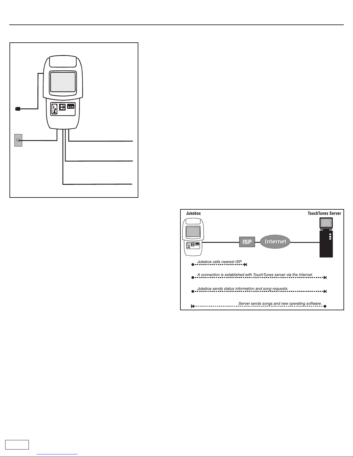
Nightly communications
Every night the jukebox calls the TouchTunes server. This call serves
several important purposes:
• Reports daily income: TouchTunes uses this information to calculate
revenue for the jukebox.
• Reports the number of plays for each song: This is required so that
TouchTunes can track its royalty obligations and make the
appropriate payments to music publishers.
• Downloads updates to the jukebox software (if required): This
ensures that whenever updates are available, all jukeboxes in the field
are automatically upgraded.
• Downloads new songs: Operators can create a list of songs they
want to add to the jukebox and the songs are automatically
downloaded when the jukebox calls the server. The jukebox also has a
Vote for Download feature. When enabled, it allows customers to
vote for their favorite songs. The song that obtains the most votes
every week is downloaded and added to the jukebox. If you signed up
for the revenue enhancement program, TouchTunes automatically
manages the songs on the jukebox for maximum profitability during
the nightly call.
• The jukebox uses the Internet to communicate with the TouchTunes
server. Using the area code of the location’s phone number, the
jukebox determines the nearest ISP (Internet service provider) to call.
Failure to communicate
A jukebox that fails to communicate with the TouchTunes server will
eventually be disabled. This occurs as follows:
• If the jukebox fails to communicate with the TouchTunes server for
several consecutive days, a red telephone icon appears in the top
right corner of the Attract screen. This warning icon will appear for
the next few days. If you touch this icon, the jukebox displays the
message “This jukebox will be disabled in XX days.”
• When the jukebox becomes inoperable, instead of the Attract screen
you will see the message “This jukebox has been deactivated. Please
contact your operator.”
Phone line
Cat 5 cable for Zone 1
Cat 5 cable for Zone 2
Cat 5 cable for Zone 3
Maestro
AC power
3 of 12
Installing the phone line
Maestro requires an analog telephone line to communicate with the
TouchTunes server. Once connected, Maestro will call out once daily at the
time you specify (typically during non-business hours). This daily
communication is critical for proper operation. It enables Maestro to
retrieve system software updates and download new music.
Maestro can usually share an existing phone line with other devices, such
as phones, fax machines, or alarm systems. A dedicated phone line is not
necessary. However, some devices, such as computerized telephones,
lottery terminals, and ATMs, can cause conflicts on a shared line. You can
usually resolve these conflicts by contacting the operator of the other
equipment and coordinating call and answer times.
• Alarm systems: Most current alarm systems communicate over
telephone wiring. These systems usually have the telephone line
connected directly from the demarcation point (service entry) to the
input side of the alarm. Telephones and Maestro should be connected
to the phone side of the alarm.
• Digital phone systems: If the location has a digital phone system, the
Maestro phone line must be connected to the analog line in front of
the digital phone system.
Running a new phone cable
Note: As of February 1, 1996, the telephone company states, for singleline residence or business telephone service, that the owner is
responsible for the installation and maintenance of telephone wiring
after the demarcation point.
In most cases, you will need to run a new phone cable from the
demarcation point (also known as the telephone network interface, or
service entry) to the spot where Maestro will be installed.
The demarcation point is located where the outside phone line enters the
building. By running new, quality cable directly from this point to Maestro,
you can avoid potential problems caused by existing wire connections
that may be poorly made.
Recommended parts and tools
• Phone line polarity tester (available at Radio Shack).
• Phone cable with RJ11 connectors (7' long) included in the parts kit.
Used to connect Maestro to the phone jack.
• Four-conductor telephone modular wall jack.
• Four-conductor round telephone cable. Used to connect the phone
line from the demarcation point to the wall jack.
• Any analog phone without filters or a Butt-in set. Used to listen to the
newly installed phone line.
Installation tips
• Always use good quality cable and make the cable run as short as
possible. This will cut down on potential problems with line noise.
• Avoid using phone line splitters to tap into an existing jack.
• Make sure that the phone line is not routed over or near fluorescent
or neon lights. Electrical noise generated by these devices can
interfere with the phone line.
• It is not uncommon for a telephone line to pick up a radio station. To
diagnose this problem, use a cheap telephone without filtering, or a
Butt-In set. You must determine if the noise is on the telephone
company's equipment or being picked up on the inside wiring.
Disconnect the inside wiring at the demarcation point. If the noise
disappears, it is on the phone company's wiring and they must fix it.
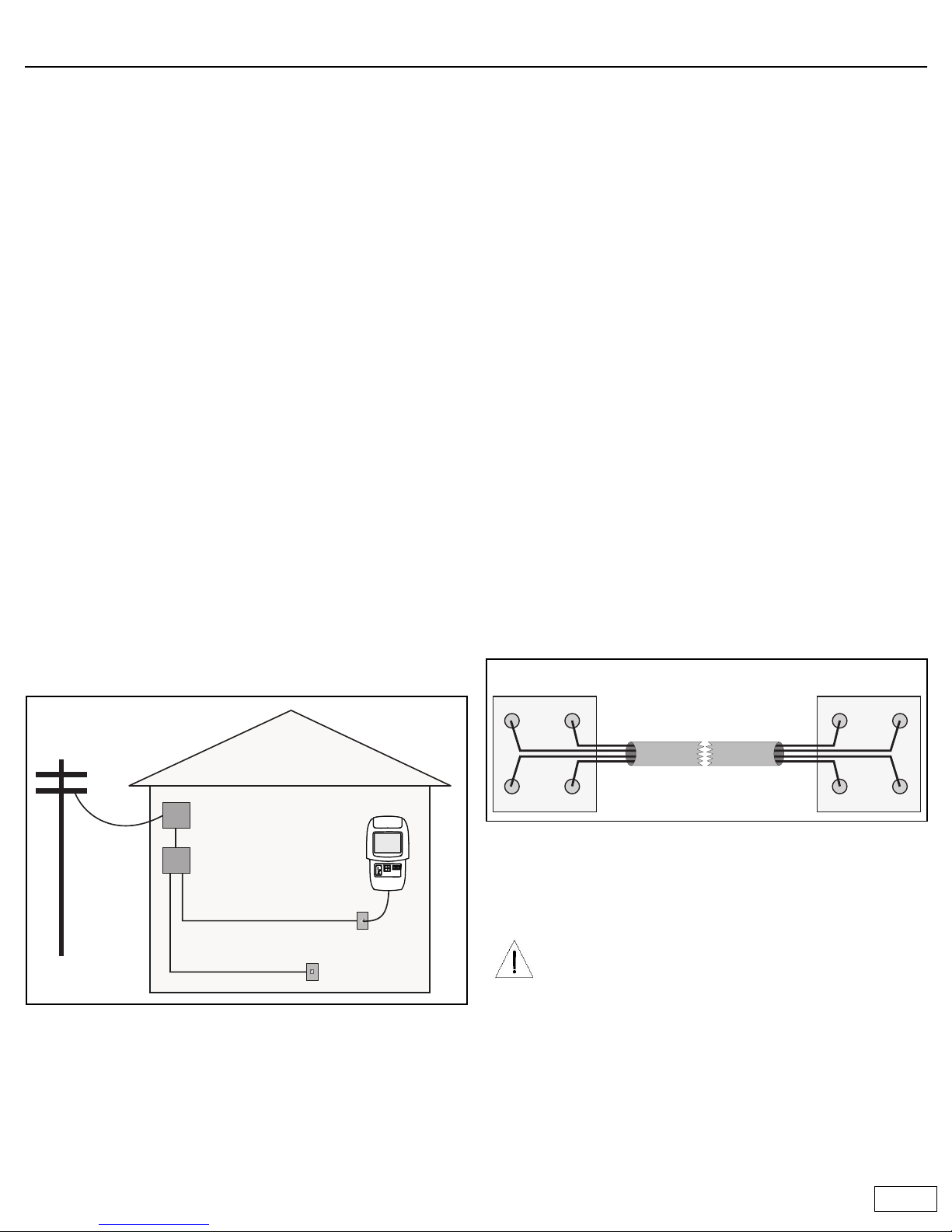
• Wire both ends of the phone cable to the same colors (as indicated).
The jukebox generally uses the red and green wires for its phone line.
Typically, the green wire has positive electrical polarity and the red
wire is negative.
• Once installation is complete, use a polarity tester to verify the line.
• Make a call to any 877 prefix toll free number to ensure that calls to
this prefix are not blocked.
Demarcation point
Phone line
Wire distribution device
Existing phone line
New phone line for Maestro
Location
CAUTION: Telephone wires typically carry low voltage, but if
you are touching the wires when the phone rings, you can
receive a substantial jolt. Enough current is still sent through
the line to activate the old style mechanical ringing devices.
Do not work on phone lines during a thunder storm, since an
electrical strike can send excessive current down the line.
To minimize the risk, always make the connection to the live
phone line or to the demarcation point after you have
completed all other connections.
Demarcation point or
wire distribution device
New phone cable
BlackBlack RedRed
YellowYellow
GreenGreen
Modular jack
4 of 12
Installing Maestro
The following diagram provides an overview of the installation sequence. Refer to page 5 for installation instructions.
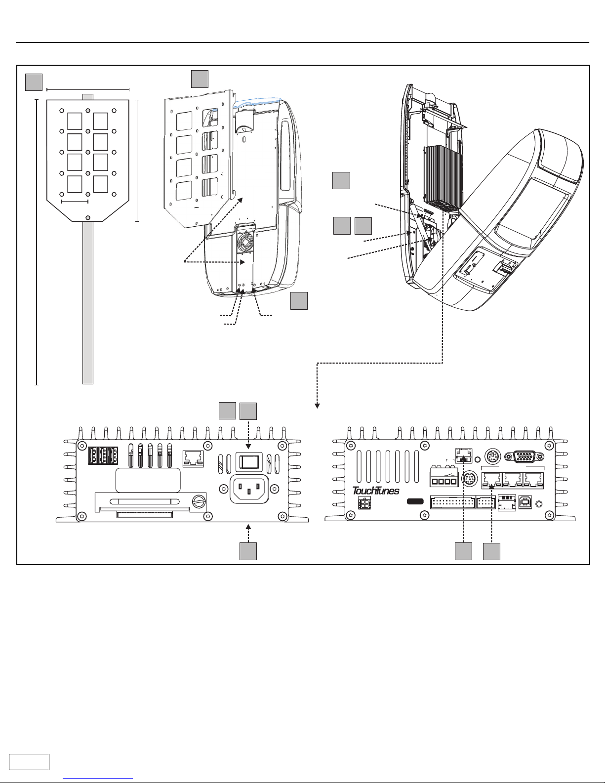
Components overview
a Cable channels: All cables are routed through the cable channels on
the rear of the unit.
b Volume buttons: Provide manual control of the jukebox volume.
c Night Mode button: Turns off the monitor, lights, and bill collector.
The jukebox computer remains active so it can call the TouchTunes
server at the preset time.
d System power switch: Turns off all power to the jukebox.
e Wire strength-relief bracket: This is where cables are routed out of
the jukebox and into the cable channels. Once the bracket is
tightened, the cables are secure so they cannot be pulled out.
fFan: Provides cooling. A replacement filter is supplied in the parts kit.
g Connector panel: This is where audio connections are made, the
phone cable is connected, and the hard drive is installed.
System
power switch
Wire strengthrelief bracket
Fan
Volume increase
Volume decrease
Cable
channels
Mount top of bracket 67 inches from floor
Night mode
button
1
1
5
5
9
9
10
11
10
11
5 inches
22.6 inches
12.9 inches
2
2
a)
b)
(Note: Buttons are slightly recessed.)
d)
e)
f)
Wing nut
7
7
c)
16
16
3
3
VIDEOKBDTELCO
AUDIO OUT
13
LINE IN
RST
USBDMX
MNG
COM1
MIC
12
P
W
R
D
I
A
G
HD
TO CTL
P/N: 300114-
2
SW
(-) (+)
NETWORK
2
USB
13
ON OFF
Serial No.
ACT
LNK
100 - 120VAC
50/60Hz 2.0A MAX.
NO USER-SERVICEABLE PARTS INSIDE
BottomTop
12
12
14
14
 Loading...