

Page 1

Page 2
Safety information
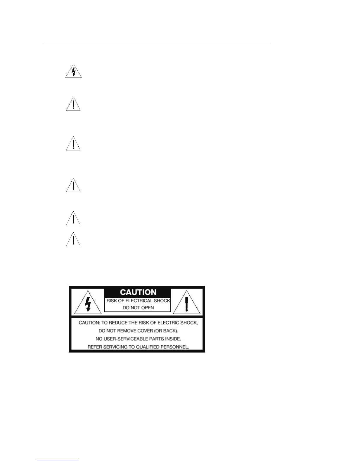
CAUTION: The lightning flash with arrowhead symbol within an equilateral
triangle signifies the presence of uninsulated dangerous voltage within the
system enclosure that may be of sufficient magnitude to constitute a risk of
electrical shock.
CAUTION: The exclamation point within an equilateral triangle signifies the
presence of important operating and maintenance instructions in this guide.
CAUTION: Ovation components are heavy and represent a serious safety hazard
if their mounting system should fail. Therefore, installation should only be
performed by an experienced installer or licensed contractor that is familiar with
standard rigging, mounting, and hanging practices, as recognized by a licensed
engineer or governmental agency in your area.
CAUTION: Ovation mounting components are UL listed and CSA approved only
when used as specified in this guide. Any other use or modification of the
mounting components is expressly prohibited, as this may present an
unacceptable risk of structural failure.
CAUTION: To reduce the risk of fire or electrical shock, do not expose the system
to rain or moisture.
CAUTION: See product enclosure for safety related markings.
ii
Page 3

Important safety instructions
• Read the instructions for all components before using this product.
• Keep these instructions for future reference.
• Heed all warnings on the product and in the this guide.
• Follow all instructions.
• Do not use this apparatus near water or moisture
• Clean only with a dry cloth and as directed
• Do not block any ventilation openings and install in accordance the instructions in this guide.
To ensure reliable operation of the product and to protect it from overheating, put the product
in a position and location that will not interfere with its proper ventilation
• Do not install near any heat sources, such as radiators, heat registers, stoves or other apparatus
(including amplifiers) that produce heat.
• Do not defeat the safety purposes of the polarized or grounding-type plug. A polarized plug
has two blades with one wider than the other. A grounding-type plug has two blades and a
third grounding prong. The wider blade or the third grounding prong are provided for your
safety. If the provided plug does not fit in your outlet, consult an electrician for replacement of
the obsolete outlet.
Important safety instructions
• Protect the power cord from being walked on or pinched, particularly at the plugs, convenience
receptacles, and the point where they exit from the apparatus.
• Only use attachments/accessories specified by the TouchTunes.
• Unplug this apparatus during lightning storms or when unused for long periods of time. To
prevent damage to this product during a lightning storm, or if the product will not be used for
an extended period of time, unplug its power cord from the wall outlet and disconnect the
antenna or cable system.
• Refer all servicing to qualified service personnel. Servicing is required when the apparatus has
been damaged in any way: such as power-supply cord or plug is damaged; liquid has been
spilled or objects have fallen into the apparatus; the apparatus has been exposed to rain or
moisture, does not operate normally, or has been dropped - Do not attempt to service this
product yourself. Opening or removing covers may expose you to dangerous voltages or other
hazards
• To prevent risk of fire or electrical shock, avoid overloading wall outlets, extension cords, or
integral convenience receptacles.
• Do not let objects or liquid enter the product as they may touch dangerous voltage points or
short-out parts that could result in a fire or electric shock.
• See product enclosure for safety related markings.
iii
Page 4

FCC Notice
This equipment has been tested and found to comply with limits for a Class A digital device,
pursuant to Part 15 of the FCC rules. These limits are designed to provide reasonable protection
against harmful interference in a commercial environment. This equipment generates, uses, and
can radiate radio frequency energy and, if not installed and used in accordance with the
instruction manual, may cause harmful interference to radio communications. Operation of this
equipment in a residential area is likely to cause harmful interference in which case the user will
be required to correct the interference at his own expense.
Note: Unauthorized modification of the receiver or radio remote control could void the user's
authority to operate this equipment.
This product complies with the Canadian ICES-003 Class A specification.
iv
Page 5

Table of Contents
Safety information . . . . . . . . . . . . . . . . . . . . . . . . . . . . . . . . . . . . . . . . . . . . . . . . . . . . . . . . . . . . . . . . . . . . . . . . . . . . . . . . . . . . . . . . . .ii
Important safety instructions . . . . . . . . . . . . . . . . . . . . . . . . . . . . . . . . . . . . . . . . . . . . . . . . . . . . . . . . . . . . . . . . . . . . . . . . . . . . . . . . iii
FCC Notice . . . . . . . . . . . . . . . . . . . . . . . . . . . . . . . . . . . . . . . . . . . . . . . . . . . . . . . . . . . . . . . . . . . . . . . . . . . . . . . . . . . . . . . . . . . . . . . . . . iv
1 Introduction 1
About this guide. . . . . . . . . . . . . . . . . . . . . . . . . . . . . . . . . . . . . . . . . . . . . . . . . . . . . . . . . . . . . . . . . . . . . . . . . . . . . . . . . . . . . . . . . . . . . 1
Related Documentation . . . . . . . . . . . . . . . . . . . . . . . . . . . . . . . . . . . . . . . . . . . . . . . . . . . . . . . . . . . . . . . . . . . . . . . . . . . . . . . . . . . . . 1
Writing Conventions. . . . . . . . . . . . . . . . . . . . . . . . . . . . . . . . . . . . . . . . . . . . . . . . . . . . . . . . . . . . . . . . . . . . . . . . . . . . . . . . . . . . . . . . .2
Contacting Technical Support. . . . . . . . . . . . . . . . . . . . . . . . . . . . . . . . . . . . . . . . . . . . . . . . . . . . . . . . . . . . . . . . . . . . . . . . . . . . . . . . 2
2 Preparing for Jukebox Installation 3
Unpacking and Checking Jukebox Components . . . . . . . . . . . . . . . . . . . . . . . . . . . . . . . . . . . . . . . . . . . . . . . . . . . . . . . . . . . . . . 3
Setting Up a Broadband or Dial-up Connection . . . . . . . . . . . . . . . . . . . . . . . . . . . . . . . . . . . . . . . . . . . . . . . . . . . . . . . . . . . . . . . 4
Preparing Tools for Installation. . . . . . . . . . . . . . . . . . . . . . . . . . . . . . . . . . . . . . . . . . . . . . . . . . . . . . . . . . . . . . . . . . . . . . . . . . . . . . . 5
3 Installing the Ovation Jukebox 7
Installing the Ovation Jukebox . . . . . . . . . . . . . . . . . . . . . . . . . . . . . . . . . . . . . . . . . . . . . . . . . . . . . . . . . . . . . . . . . . . . . . . . . . . . . . .7
Attach and level the wall bracket . . . . . . . . . . . . . . . . . . . . . . . . . . . . . . . . . . . . . . . . . . . . . . . . . . . . . . . . . . . . . . . . . . . . . . . .7
Hang the Ovation. . . . . . . . . . . . . . . . . . . . . . . . . . . . . . . . . . . . . . . . . . . . . . . . . . . . . . . . . . . . . . . . . . . . . . . . . . . . . . . . . . . . . . . 8
Open the Ovation. . . . . . . . . . . . . . . . . . . . . . . . . . . . . . . . . . . . . . . . . . . . . . . . . . . . . . . . . . . . . . . . . . . . . . . . . . . . . . . . . . . . . . . 9
Replacing the Lock for the Ovation. . . . . . . . . . . . . . . . . . . . . . . . . . . . . . . . . . . . . . . . . . . . . . . . . . . . . . . . . . . . . . . . . . . . . . . . . . . 11
Installing the Hard Drive . . . . . . . . . . . . . . . . . . . . . . . . . . . . . . . . . . . . . . . . . . . . . . . . . . . . . . . . . . . . . . . . . . . . . . . . . . . . . . . . . . . . . 11
Power off the Ovation. . . . . . . . . . . . . . . . . . . . . . . . . . . . . . . . . . . . . . . . . . . . . . . . . . . . . . . . . . . . . . . . . . . . . . . . . . . . . . . . . . . 12
Install the hard drive in the MJS . . . . . . . . . . . . . . . . . . . . . . . . . . . . . . . . . . . . . . . . . . . . . . . . . . . . . . . . . . . . . . . . . . . . . . . . . 12
Connecting the Ovation to the Telephone or Broadband Network . . . . . . . . . . . . . . . . . . . . . . . . . . . . . . . . . . . . . . . . . . . . 14
Accessing the cable channel for the Ovation. . . . . . . . . . . . . . . . . . . . . . . . . . . . . . . . . . . . . . . . . . . . . . . . . . . . . . . . . . . . .14
Connect the Ovation to the broadband network . . . . . . . . . . . . . . . . . . . . . . . . . . . . . . . . . . . . . . . . . . . . . . . . . . . . . . . . .15
Connect the Ovation to the telephone network. . . . . . . . . . . . . . . . . . . . . . . . . . . . . . . . . . . . . . . . . . . . . . . . . . . . . . . . . .16
Connecting Audio Speakers and Sources to the Ovation . . . . . . . . . . . . . . . . . . . . . . . . . . . . . . . . . . . . . . . . . . . . . . . . . . . . . . 18
Connect external speakers to the Ovation . . . . . . . . . . . . . . . . . . . . . . . . . . . . . . . . . . . . . . . . . . . . . . . . . . . . . . . . . . . . . . .18
Connecting Power to the Ovation . . . . . . . . . . . . . . . . . . . . . . . . . . . . . . . . . . . . . . . . . . . . . . . . . . . . . . . . . . . . . . . . . . . . . . . . . . . . 19
Connect the power cord to the Ovation . . . . . . . . . . . . . . . . . . . . . . . . . . . . . . . . . . . . . . . . . . . . . . . . . . . . . . . . . . . . . . . . . 19
Tighten the wire strength-relief bracket . . . . . . . . . . . . . . . . . . . . . . . . . . . . . . . . . . . . . . . . . . . . . . . . . . . . . . . . . . . . . . . . .19
Turn on power to the MJS. . . . . . . . . . . . . . . . . . . . . . . . . . . . . . . . . . . . . . . . . . . . . . . . . . . . . . . . . . . . . . . . . . . . . . . . . . . . . . . 20
Close the Ovation case . . . . . . . . . . . . . . . . . . . . . . . . . . . . . . . . . . . . . . . . . . . . . . . . . . . . . . . . . . . . . . . . . . . . . . . . . . . . . . . . . . 21
Activate the Ovation screen . . . . . . . . . . . . . . . . . . . . . . . . . . . . . . . . . . . . . . . . . . . . . . . . . . . . . . . . . . . . . . . . . . . . . . . . . . . . .21
Page 6

toc
4Activating the Jukebox 23
Overview. . . . . . . . . . . . . . . . . . . . . . . . . . . . . . . . . . . . . . . . . . . . . . . . . . . . . . . . . . . . . . . . . . . . . . . . . . . . . . . . . . . . . . . . . . . . . . . . . . . . 23
Activation Procedure . . . . . . . . . . . . . . . . . . . . . . . . . . . . . . . . . . . . . . . . . . . . . . . . . . . . . . . . . . . . . . . . . . . . . . . . . . . . . . . . . . . . . . . .24
Error Scenarios . . . . . . . . . . . . . . . . . . . . . . . . . . . . . . . . . . . . . . . . . . . . . . . . . . . . . . . . . . . . . . . . . . . . . . . . . . . . . . . . . . . . . . . . . . . . . . 35
5Disclaimer 37
Page 7

Introduction
Welcome to the Quick Start Guide for the TouchTunes Ovation jukebox! This
chapter provides you with information about audience pre-requisites, related
documentation, and how to get customer support.
About this guide
Congratulations on choosing a TouchTunes Ovation jukebox! This guide explains how to
prepare for, install and activate your new TouchTunes jukebox. TouchTunes highly recommends
reading this guide to familiarize yourself with the installation procedure before installing your
Ovation.
Related Documentation
This guide is designed to get you started quickly with installing and activating a jukebox in a
location. For more detailed documentation, refer to the following documents:
• The TouchTunes Jukebox Software 3.0 Installation Guide
• The TouchTunes Gen 3 Hardware Operators Manual
• The TouchTunes Gen 3 Software Operators Manual
• The TouchTunes Dashboard User Guide.
You can access any of these documents by doing the following:
• If you do not have access to the TouchTunes Dashboard, request a copy from TouchTunes
Technical Support. See “Contacting Technical Support” on page 2.
• If you have access to the TouchTunes Dashboard, log on to the Dashboard and open the
Documentation page. See the TouchTunes Dashboard User Guide.
1
Page 8
Introduction
Writing Conventions
What are the writing conventions used in this guide?
This guide uses the following documentation conventions.
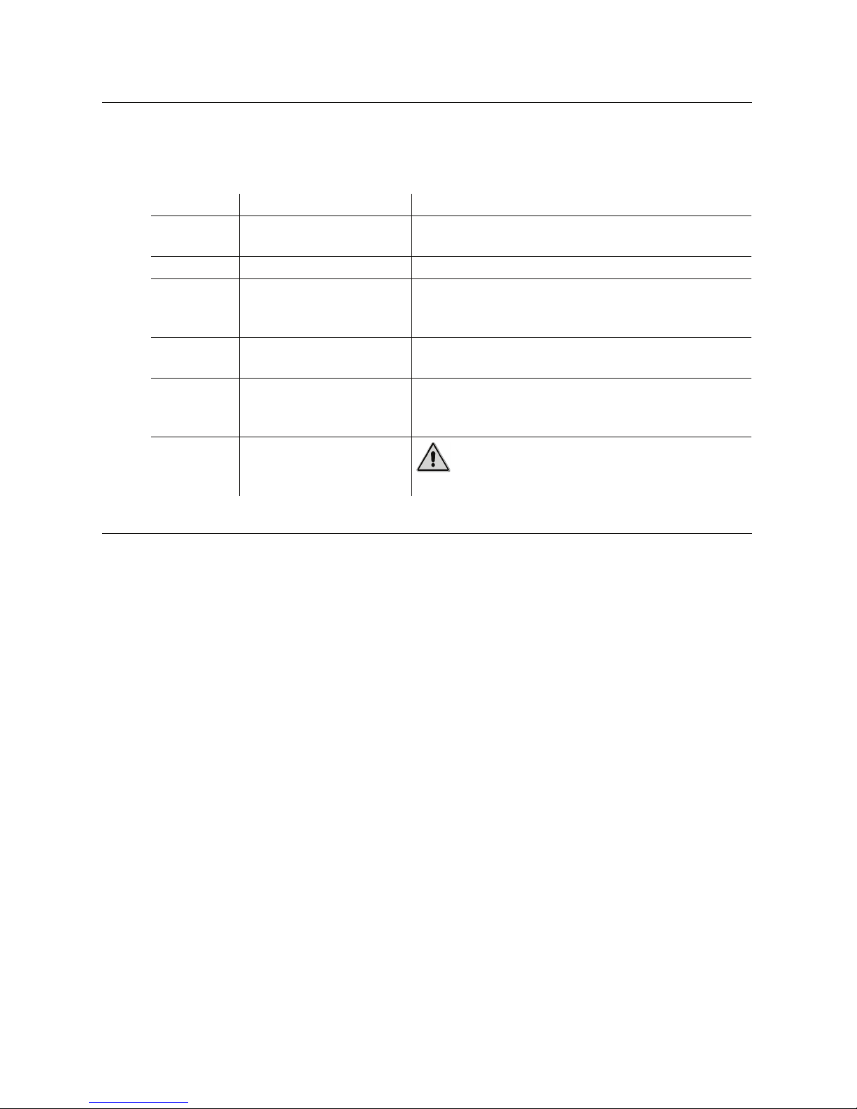
Notation: Usage: Example:
Right-click Click with the rightmost
Italic A folder or file path. Open C:\My Documents and Settings\My Music.
Bold Menu or button
Vertical bar Separates menu
Bold with a
colon
Exclamation
point within
a triangle
mouse button.
commands, as well as
labelled areas on the UI.
commands.
Description of what a UI
element in a screenshot
does.
Identifies operating and
maintenance information
to know before use.
Right-click the image and choose Save Picture As.
Choose My Jukeboxes from the Navigation menu.
Click OK when prompted to continue.
Navigate to the Broadband Settings area.
Choose Tou c hTu ne s | Contacts from the Navigation
menu.
Jukebox Location: Lists jukeboxes by their current
location.
Caution: Power off the unit before continuing.
Contacting Technical Support
You can contact the TouchTunes Technical Support department for assistance using either of the
following methods:
• Call the Technical Support department toll-free at 1-888-711-5853. Before calling, write down
the jukebox ID number underneath the front of the Ovation case or beside the inside fan.
TouchTunes requires this ID number to provide you with the proper assistance.
Note: If you are outside of the toll-free area, you can still contact the TouchTunes Technical
Support department by dialling 1-847-419-3300 and pressing 1 when prompted. Long-distance
telephone charges may apply if you are calling from outside of the toll-free area.
• Email the Technical Support department from the Contacts page on the TouchTunes
Dashboard; see the TouchTunes Dashboard User Guide. You can also use this page to contact
other departments at TouchTunes, such as the Music, Sales and Finance departments.
2
Page 9

Preparing for Jukebox Installation
This chapter explains how to prepare to install a TouchTunes jukebox for a
location, including setting up communications connections and unpacking
the jukebox.
Unpacking and Checking Jukebox Components
A TouchTunes jukebox is delivered in several boxes, including boxes for the jukebox hardware
components and a parts kit. The following table shows the dimensions and weight of the
Ovation jukebox:
Height Width Depth Weight
Crated
Uncrated
41” 32” 18” 142 lbs.
37 1/4” 27 1/4” 11 1/4” 125 lbs.
Before you install the jukebox, you must ensure that you have received all jukebox hardware
components and that both hardware components and the items in parts kit are in good
condition.
To check that you have all jukebox components:
1. Verify that you have received the following hardware components for the Ovation jukebox:
Component
Quantity
1 Ovation Digital Jukebox
1 Ovation wall bracket
1Power cord
1Parts kit
Component
Description
3
Page 10
Preparing for Jukebox Installation
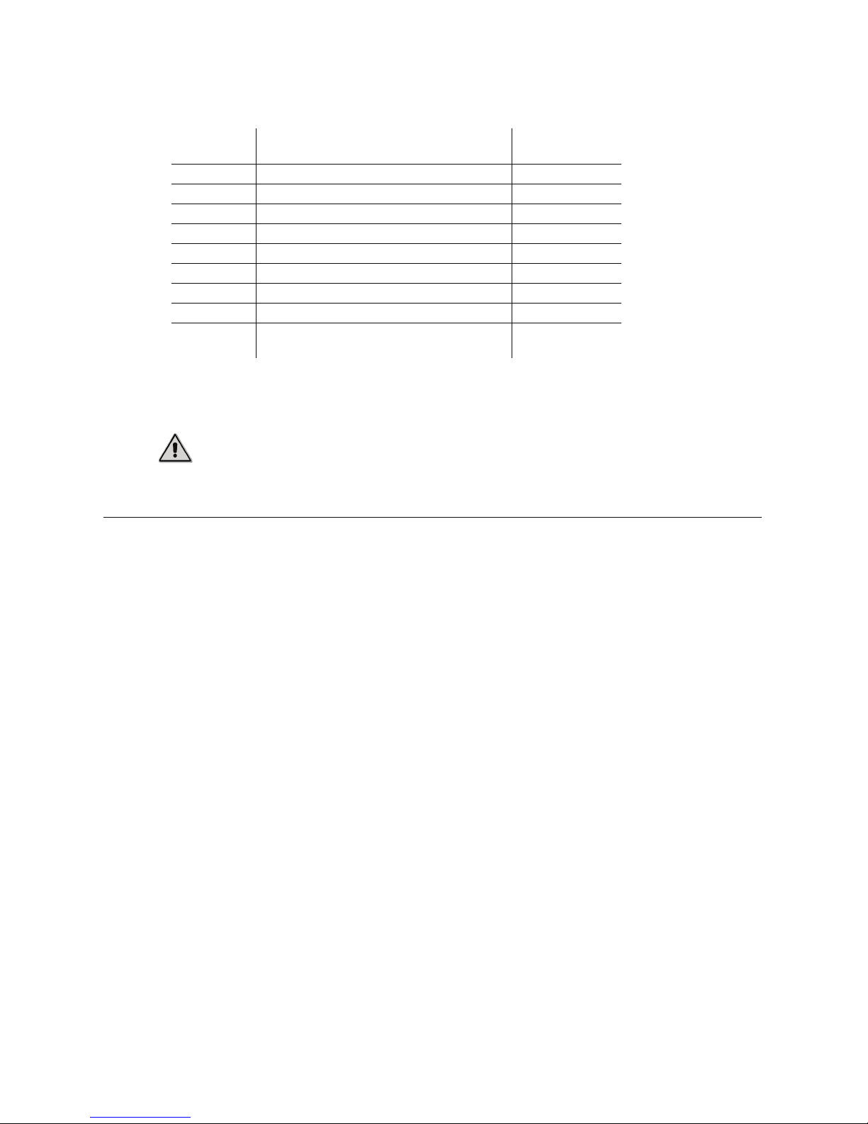
2. Open the Parts kit and then verify that it contains all of the following components:
Component
Quantity
1 Remote control 700031-001
1 Remote control mounting bracket 400188-001
2AAA batteries
2 Keys (Ilco #549) 400157-001
1 Female RCA to DIN adapter 300141-012
1 Male RCA to DIN adapter 300143-012
3 Eurostyle terminal connector (4-position) 100000-001
1 USB Modem (Optional) 300223-001
1 USB Modem cable with USB A-type an d B-type
Component
Description
connectors (Optional)
3. Check the condition of all hardware components and parts kit items to ensure they are in
good condition.
Caution: Do not attempt to installation if any jukebox hardware component or item in
the parts kit is damaged. Contact your distributor or TouchTunes to report the damage
immediately and request replacement parts.
Setting Up a Broadband or Dial-up Connection
Every night, a TouchTunes jukebox contacts the main TouchTunes server over the Internet to do
the following tasks:
• Download any new songs chosen by location owner or operator through the TouchTunes
Dashboard, as well as those chosen by the users using the Vote for Download feature.
TouchTunes
Part Number
300223-001
• Download any new updates to the jukebox system software.
• Report the number of plays per song for music royalty calculations.
• Report daily income for the jukebox.
The connection to the Internet is provided through an Internet Service Provider (ISP). ISPs
normally offer two different types of Internet connections: dial-up and broadband. A jukebox
can use either of these to contact and communicate with the TouchTunes server. However, the
connection type you chose has an impact on the infrastructure needed for the jukebox as well
as the speed of jukebox communications, which are summarized below:
• Dial-up Connection: A jukebox using a dial-up connection uses the normal telephone network
to connect to the Internet and to the TouchTunes server. Dial-up connections do not require any
special hardware beyond a standard RJ-11 telephone jack and cable but communications
speeds are slower than broadband connections.
• Broadband Connection: A jukebox using a broadband connection uses a special, high-speed
network to connect to the Internet and to the TouchTunes server. Broadband connections allow
much faster communications speeds than dial-up connections, but require a broadband
modem and/or router (computer networking device) to connect the jukebox to the high-speed
network.
4
Page 11

Preparing Tools for Installation
Use the following guidelines to help you choose and set up the Internet connection type for the
jukebox:
• TouchTunes recommends using broadband Internet connections for jukeboxes whenever
possible. The broadband connection permits the jukebox to download new songs much more
quickly than over a dial-up connection. This connection also allows you to change jukebox
settings via the TouchTunes Dashboard and apply them immediately to the jukebox.
• For all connections, ensure you use high-quality cable and make the cable run as short as
possible to minimize potential problems due to line noise and interference.
• For broadband connections, note that the broadband modem and router may be included in a
single device, depending on the equipment used by the ISP and the networking setup for the
location. Both the broadband modem and the router must be installed and configured
properly for Internet access before you can set up a broadband connection for the jukebox.
• To ensure reliability for the broadband connection, TouchTunes recommends establishing a
wired connection between the jukebox and the router. Connecting the jukebox and router
wirelessly may be possible, but this type of connection is not recommended or supported.
• For dial-up connections, TouchTunes recommends running a new telephone cable from the
demarcation point (the point where the telephone line enters the building) for the location to
the jukebox. (The demarcation point may also be called the telephone network interface or
service entry point.) By running new cable from this point to the jukebox, you can avoid
potential problems caused by the existing wiring infrastructure.
• Ensure you have a USB modem before setting up the dial-up connection for a jukebox. Previous
versions of the jukebox provided an on-board modem for setting up a dial-up connection.
However, current TouchTunes jukeboxes require a USB modem for this connection. The USB
modem is an optional jukebox component and must be requested from TouchTunes.
• The telephone line used for a dial-up Internet connection can be shared with other devices,
such as an ATM or alarm system. However, you must co-ordinate call and answer times with any
other equipment that shares the same phone line to prevent scheduling conflicts between the
jukebox and another piece of equipment.
• Ensure sure you connect the jukebox to the analog line in front of the digital phone system for
dial-up connections. A jukebox cannot be connected directly to a digital phone system.
• Ensure that the telephone cable for a dial-up connection does not run close to any florescent
or neon lights as these can cause unwanted interference.
Preparing Tools for Installation
The following list shows tools that you may require to install the Ovation jukebox. Ensure that
you have all tools before beginning installation.
• Spirit level to ensure wall bracket and/or jukebox is level.
• Drill and appropriate drill bits for mounting wall bracket to wood or concrete.
• Phillips screwdriver.
• Flat-head screwdriver.
5
Page 12

Preparing for Jukebox Installation
• Anti-static wrist strap (sometimes called a conducting wrist strap).
• Adjustable wrench for tightening bolts or nuts.
• Additional flat telephone cable to reconnect the wired remote.
If you are setting up a broadband connection for the Ovation, you may also require the following
tools:
• A laptop computer with a network card and a Web browser, such as Microsoft Internet Explorer
to test Internet connectivity.
• Pre-wired Cat5 network cable (or cable, crimp tool and RJ-45 connectors) to connect the laptop
and/or jukebox to the router.
If you are setting up a dial-up connection for the Ovation, you may also require the following
tools:
• USB modem
• Phone line polarity tester.
• Extra telephone cable with RJ-11 connectors.
• Four-conductor telephone modular wall jack.
• Four-conductor round telephone cable to connect the phone line from the demarcation point
to the modular wall jack.
• A Butt-In test set or analog phone without filters to listen to the newly installed phone line.
Note: The USB modem is an optional jukebox component. If a USB modem was not included
with the jukebox, you must request it from your distributor or TouchTunes.
6
Page 13

Installing the Ovation Jukebox
This chapter explains how to install the Ovation jukebox, including setting up
its hardware, connecting it to a telephone line or broadband network as well
as attaching the power supply to the jukebox.
Installing the Ovation Jukebox
In this section, you install the Ovation wall bracket and jukebox, level it so it is stable and then
open its case.
Attach and level the wall bracket
Attach and level the wall bracket for the Ovation before hanging the unit.
Caution:
mounting system should fail. Installation of the mounting system should only be
performed by an experienced installer or licensed contractor who is familiar with standard
rigging, mounting and hanging practices as recognized by a licensed engineer or
government agency in your area.
To attach the wall bracket for the jukebox:
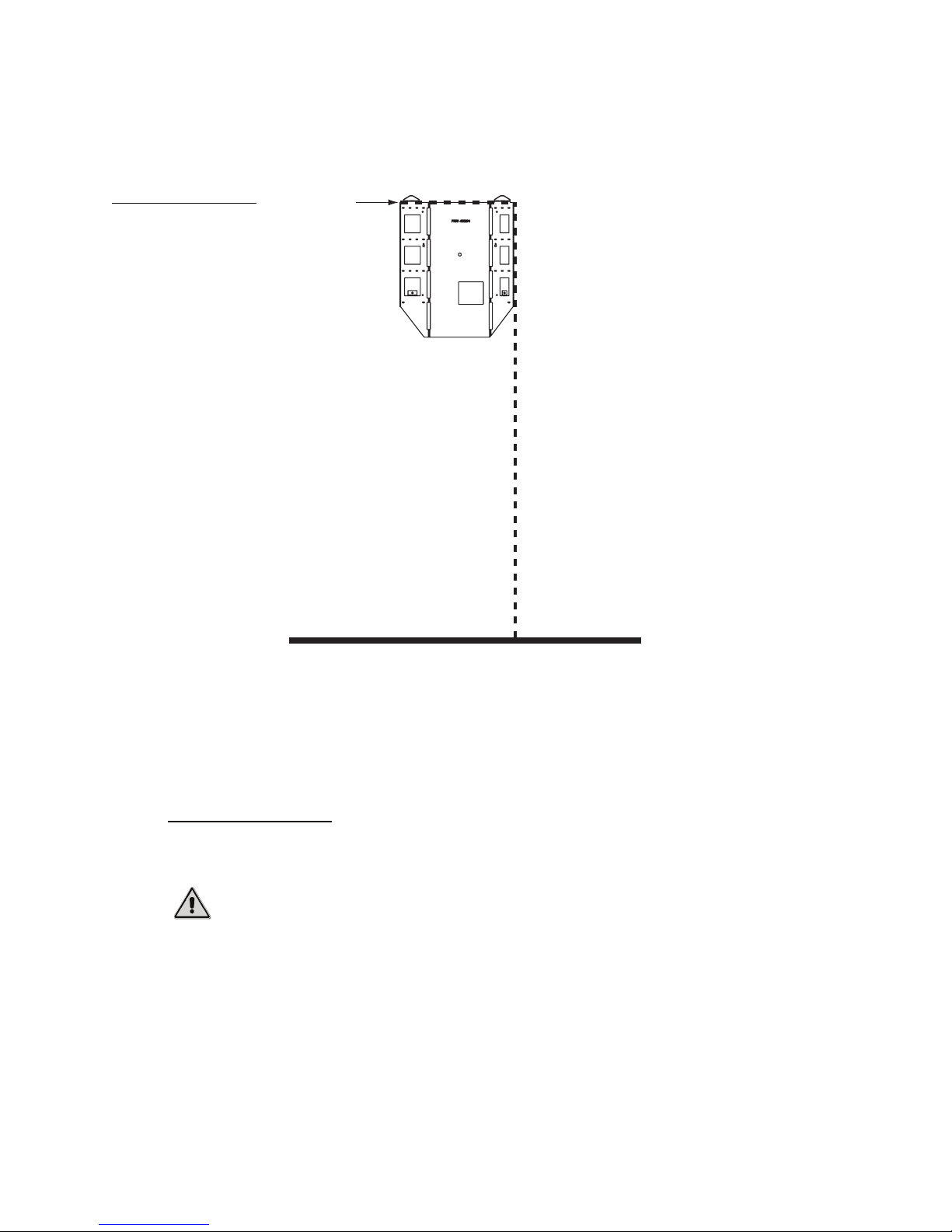
1. On the wall where the Ovation is to be installed, measure 65 inches (5’ 5”) from the floor and
mark this measurement.
This measurement identifies where the top of the bracket will be located on the wall.
2. Using the included template, mark the position for the wall bracket on the wall where you
intend to install the Ovation.
The Ovation jukebox is heavy and represents a serious safety hazard if its
7
Page 14
Installing the Ovation Jukebox
This measurement shows how far the bracket will extend along the wall. The wall bracket for
an Ovation jukebox is 25.1 inches wide, as measured from the line below the top flanges.
Figure 1
Mounting guidelines for
jukebox wall bracket
Top of
Bracket
25.1 inches across
65 inches from floor
3. Align the wall bracket with the measurements you made in steps 2 and 3.
4. Using a level, ensure the wall bracket is level both horizontally and vertically.
5. Attach the bracket to the wall using at least four (4) lag bolts and washers.
The wall bracket is attached. Continue to the next procedure to hang the Ovation console on
the bracket and attach it to the wall.
Hang the Ovation
Once the wall bracket is securely attached, hang the Ovation on the wall.
Caution: The Ovation jukebox is heavy and can cause injury if lifted incorrectly.
TouchTunes recommends at least two people perform the following procedure.
To hang the Ovation on its wall bracket:
1. Move the Ovation so it is close to the wall bracket.
2. Identify the flange hooks for the jukebox on the rear of the Ovation.
These flange hooks fit into receptacles on the wall bracket, securing the Ovation to the wall.
3. Using at least two people, lift the Ovation so that the top of the jukebox is slightly higher than
the top of the wall bracket.
8
Page 15
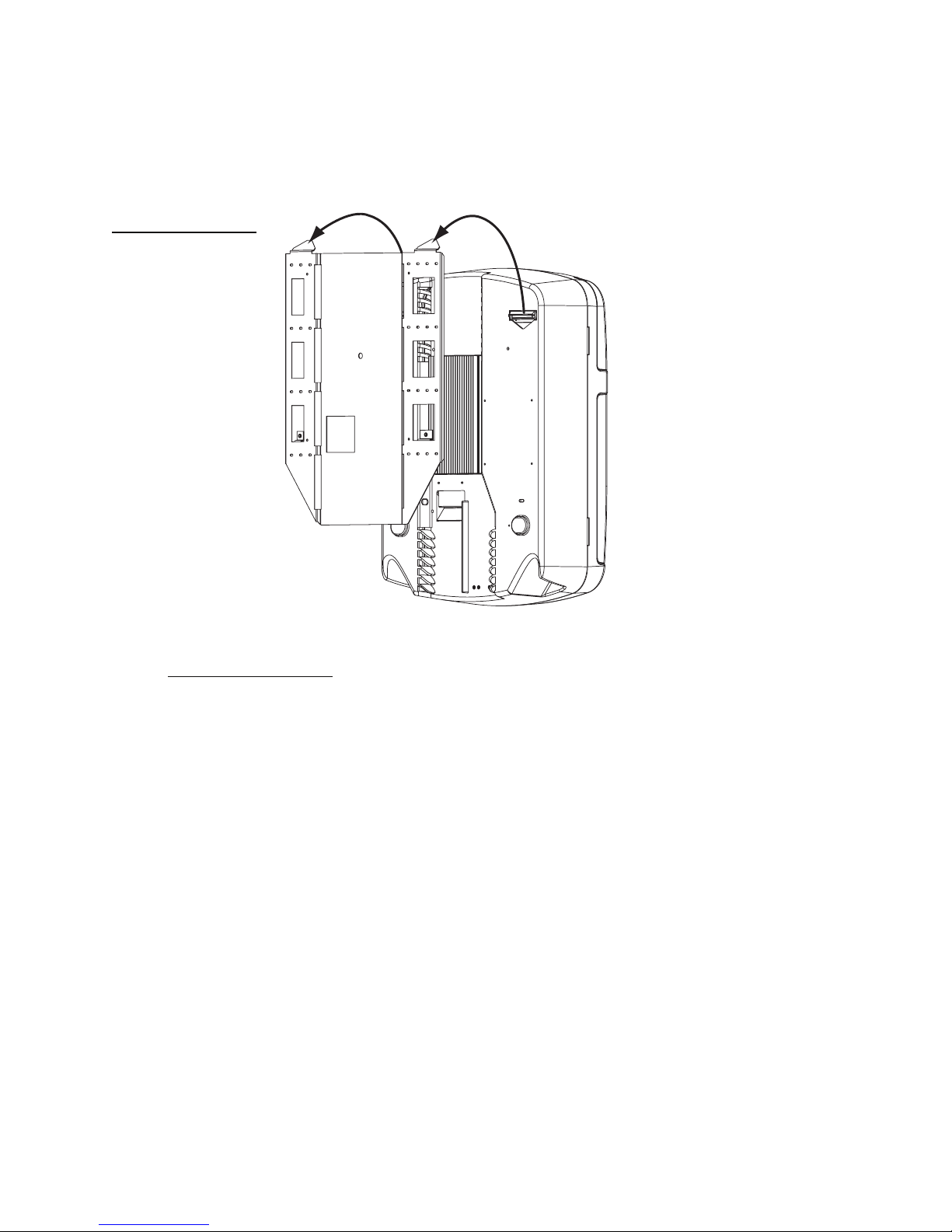
4. Align the flange hooks on the jukebox with the receptacles on the wall bracket.
5. Hang the Ovation on the wall bracket allowing the weight of the jukebox to set it into
position.
Figure 2
Mounting jukebox on the
wall bracket
Installing the Ovation Jukebox
Once you are sure the Ovation is stable, you can open up its case.
Open the Ovation
Once the Ovation is installed, open the jukebox to access its internal components. Secure the
Ovation to the wall bracket using internal screws.
To op en t h e ju kebox :
1. Locate the key for the jukebox.
New jukeboxes are always shipped with two keys. Because the locks on all TouchTunes
jukeboxes are keyed the same, you can also use a key from any other jukebox to open the new
jukebox.
9
Page 16
Installing the Ovation Jukebox
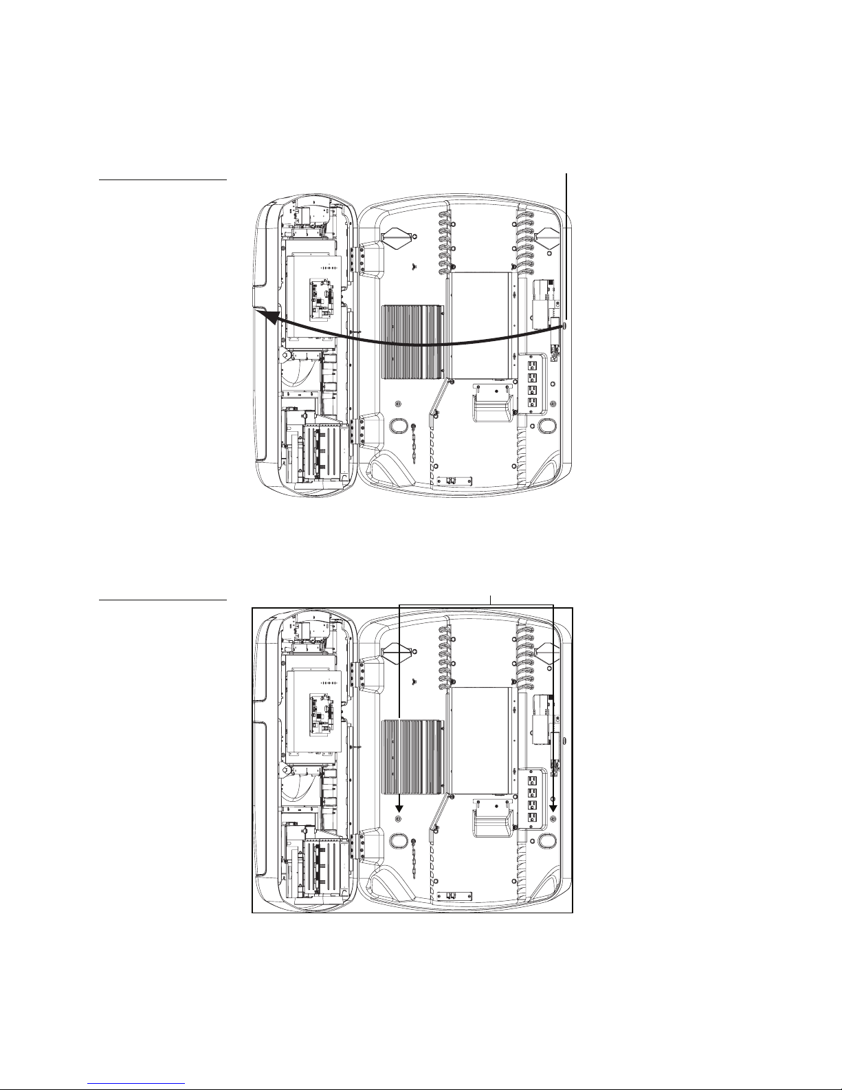
2. Unlock the Ovation from the lock on the right side of the jukebox and then slowly swing open
the Ovation case.
Figure 3
Opening the jukebox
3. Using the diagram below, identify the location of the holes for the wall bracket screws used
to secure the jukebox to the wall bracket.
Lock
Figure 4
Location for wall bracket
screws
Holes for wall bracket screws
10
Page 17
Replacing the Lock for the Ovation
5/8"
16 mm
7/64"
3 mm
7/8"
22 mm
1 1/8"
1"
0.120"
4. Attach the wall bracket screws to completely secure the Ovation to the wall bracket.
Caution:
The Ovation jukebox is NOT secure until the wall bracket screws
are installed.
Replacing the Lock for the Ovation
By default, locks for all TouchTunes Ovation jukeboxes are keyed exactly alike. You can replace
the pre-installed tubular cam lock in any TouchTunes jukebox with another lock that is keyed
differently. Replacing the lock in each jukebox improve s onsite security and significantly reduces
the chance of someone breaking in to the Ovation.
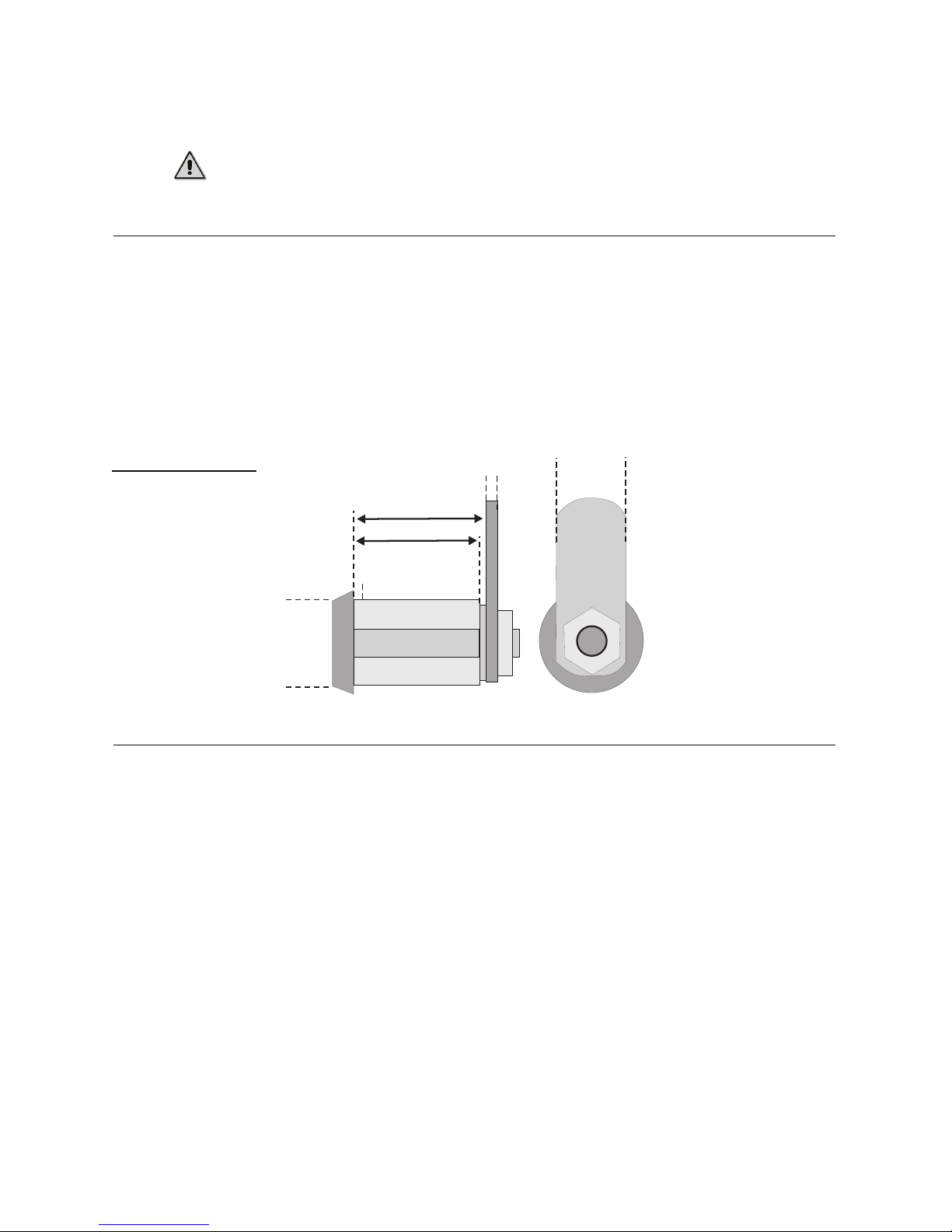
The locks shipped with TouchTunes jukeboxes are tubular cam locks with dimensions shown in
the following diagram. Ensure any replacement locks have the same dimensions before
performing the following procedure.
Figure 5
Dimensions of the tubular
cam lock used for all
Tou chTun es juke boxes
7/64"
3 mm
5/8"
16 mm
7/8"
22 mm
Installing the Hard Drive
Before installing the hard drive, you should familiarize yourself with layout of the central
computer in your Ovation jukebox, called the Modular Jukebox System (or MJS). The MJS is a
specially designed computer mounted inside the Ovation that runs the jukebox. Like a regular
laptop or desktop computer, the MJS contains a power switch, a hard drive and USB connectors
for attaching peripherals.
11
Page 18
Installing the Ovation Jukebox
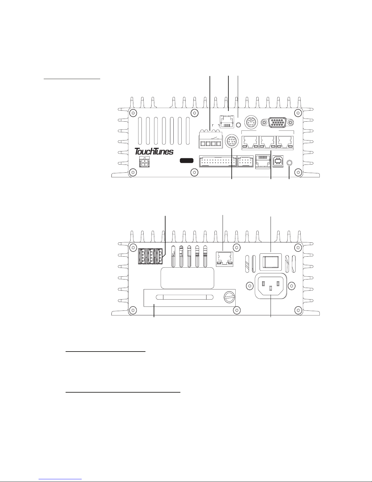
To conserve space, the MJS has connections on both its top and bottom panels. Refer to the
following diagrams to identify all components and connections on the MJS for your jukebox.
Figure 6
Layout of MJS
a b c
Top Panel
D
TO CTL
P/N: 300114-
I
A
G
MIC
P
W
R
(-) (+)
HD
12
SW
LINE IN
RST
13
COM1
def
a) Microphone connector b) Phone line connector c) Reset button d) Auxiliary audio input connector
e) Audio Out ports f) Manager button
g h i
VIDEOKBDTELCO
AUDIO OUT
2
MNG
USBDMX
Bottom Panel
ON OFF
2
13
USB
Serial No.
LNK
NETWORK
ACT
100 - 120VA C
50/60Hz 2.0A MAX.
NO USER-SERVICEABL E PARTS INSIDE
j k
g) USB ports h) Network/Broadband port i) MJS System power switch j) Hard drive
k) MJS power receptacle
Power off the Ovation
1. If necessary, ground yourself by touching an exposed piece of metal in the jukebox case.
2. Turn the MJS system power switch to OFF.
Install the hard drive in the MJS
Install the hard drive for the Ovation in its MJS.
1. Locate the hard drive for the jukebox.
The hard drive for a TouchTunes jukebox is contained in an enclosure.
12
Page 19
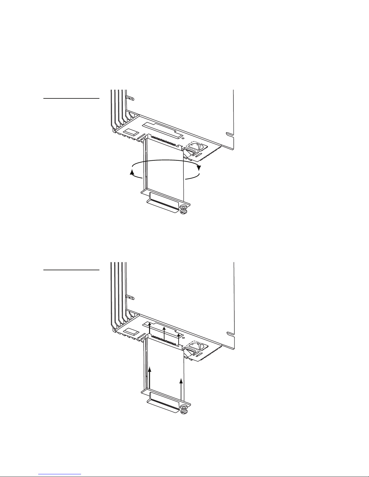
The hard drive (and its enclosure) are shipped separately from the main jukebox hardware. If
the hard drive has not yet arrived at the location, contact the vendor or distributor.
2. Align the hard drive enclosure with the slot labelled REMOVEABLE HARD DISK on the
bottom panel of the MJS.
Figure 7
Aligning the hard drive with
its slot in the MJS
Installing the Hard Drive
The hard drive enclosure cannot be inserted in its slot until it is properly aligned.
3. Insert the hard drive enclosure in the slot and then gently push the enclosure in until it is
completely seated.
Figure 8
Inserting the hard drive to
the MJS
13
Page 20
Installing the Ovation Jukebox
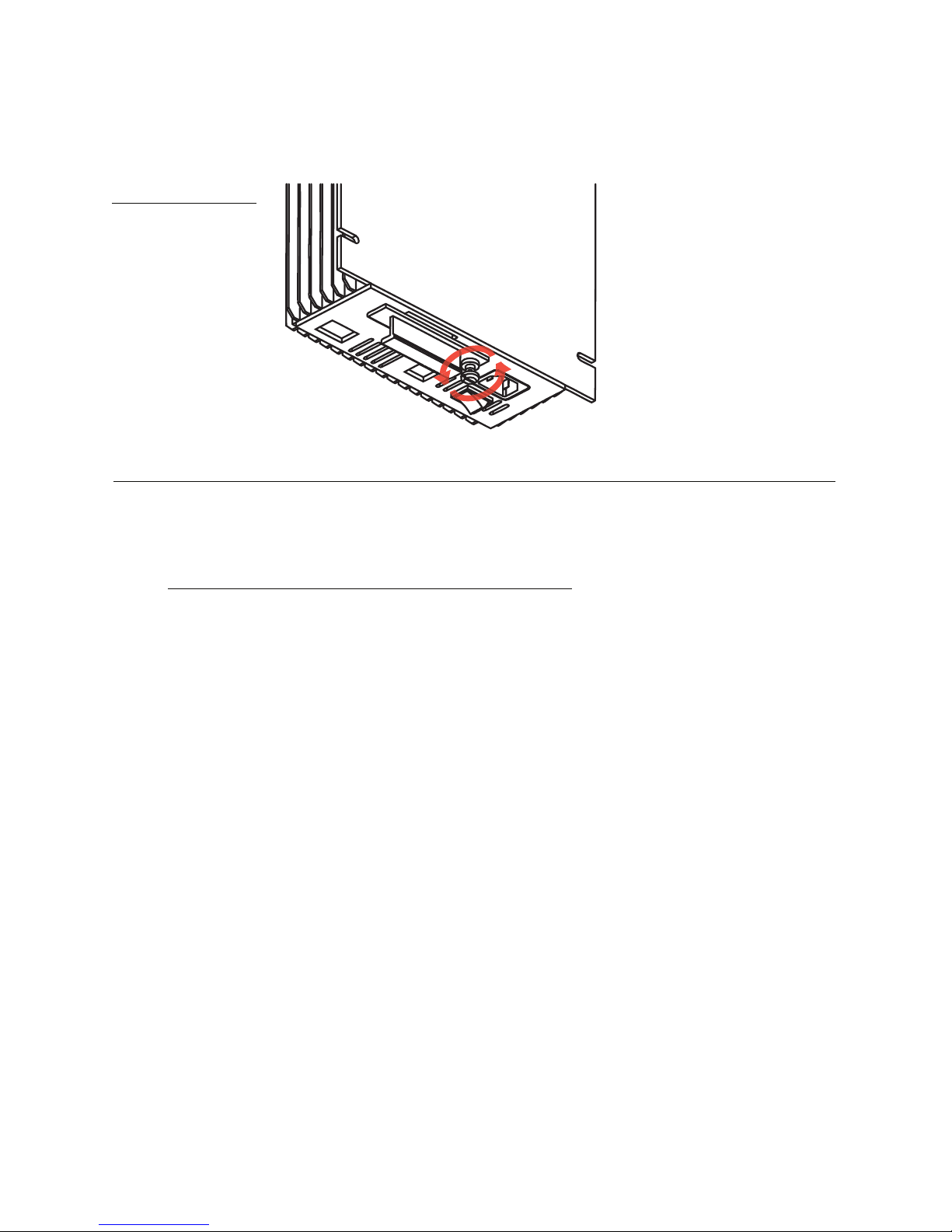
4. Using your fingers, push in and then tighten the thumb screw on the hard drive enclosure
until the thumb screw is securely tightened.
Figure 9
Tightening the thumb
screw on the hard drive
enclosure
Connecting the Ovation to the Telephone or Broadband Network
In this section, connect the Ovation to the telephone or broadband infrastructure in the location
so the jukebox can communicate with the TouchTunes server.
Accessing the cable channel for the Ovation
The Ovation is designed with a cable channel that allows you to route outside cables (such as for
telecommunications) to internal jukebox components. A wire-strain relief bracket provides slack
for cables inside the jukebox and also covers the opening to the cable channel to keep dust out.
In the following procedure, adjust this bracket to access the opening to the cable channel.
Note: Only route cables in to and out of the jukebox through the provided cable channel
opening. Do not route cables through any other openings in the jukebox, such as air vents.
Otherwise, the jukebox may overheat and shut itself down.
To prepare for cable routing in the jukebox:
1. Identify the following components for the Ovation:
• The cable channel along the back of the jukebox.
14
Page 21
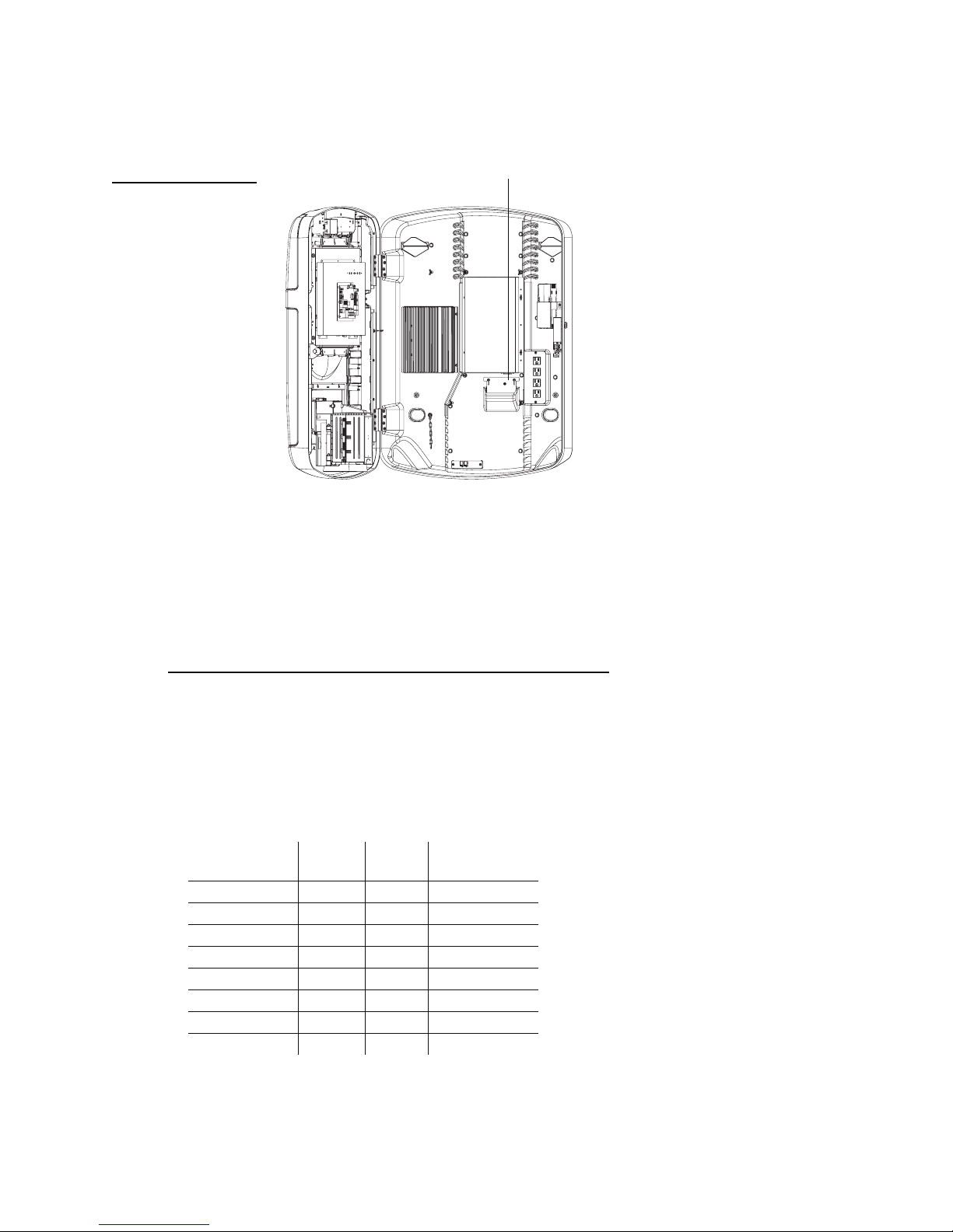
Connecting the Ovation to the Telephone or Broadband Network
• The wire-strain relief bracket shown in the diagram below.
Figure 10
Location of wire-strain relief
bracket on Ovation jukebox
2. Using a screwdriver, loosen the screws for the wire-strain relief bracket to adjust the bracket.
3. Adjust the wire-strain relief bracket so you can bring cables into the jukebox through the
cable channel opening.
4. Tighten the screws for the wire-strain relief bracket to keep open the cable channel opening.
Once the cable channel is open and the wire-strain relief bracket is loose, you are ready to
connect the jukebox to either the broadband or telephone network.
Wire-strain relief bracket
Connect the Ovation to the broadband network
You connect an Ethernet network cable from the router to the Ovation MJS to connect the
jukebox to the broadband network.
1. Locate the RJ-45 Ethernet cable for the broadband connection.
The cable used for a broadband connection is straight-wired Ethernet cable with RJ-45
connectors at both ends. You can either purchase this cable from an electronics store or wire
it yourself using the following pinout guide.
Wire Color at
Near End
White + Orange 1 1 White + Orange
Orange 2 2 Orange
White + Green 3 3 White + Green
Blue 4 4 Blue
White + Blue 5 5 White + Blue
Green 6 6 Green
White + Brown 7 7 White + Brown
Brown 8 8 Brown
2. Connect either end of the cable to the broadband modem or router.
Pin at
Near End
Pin at
Far End
Wire Color at
Far End
15
Page 22
Installing the Ovation Jukebox
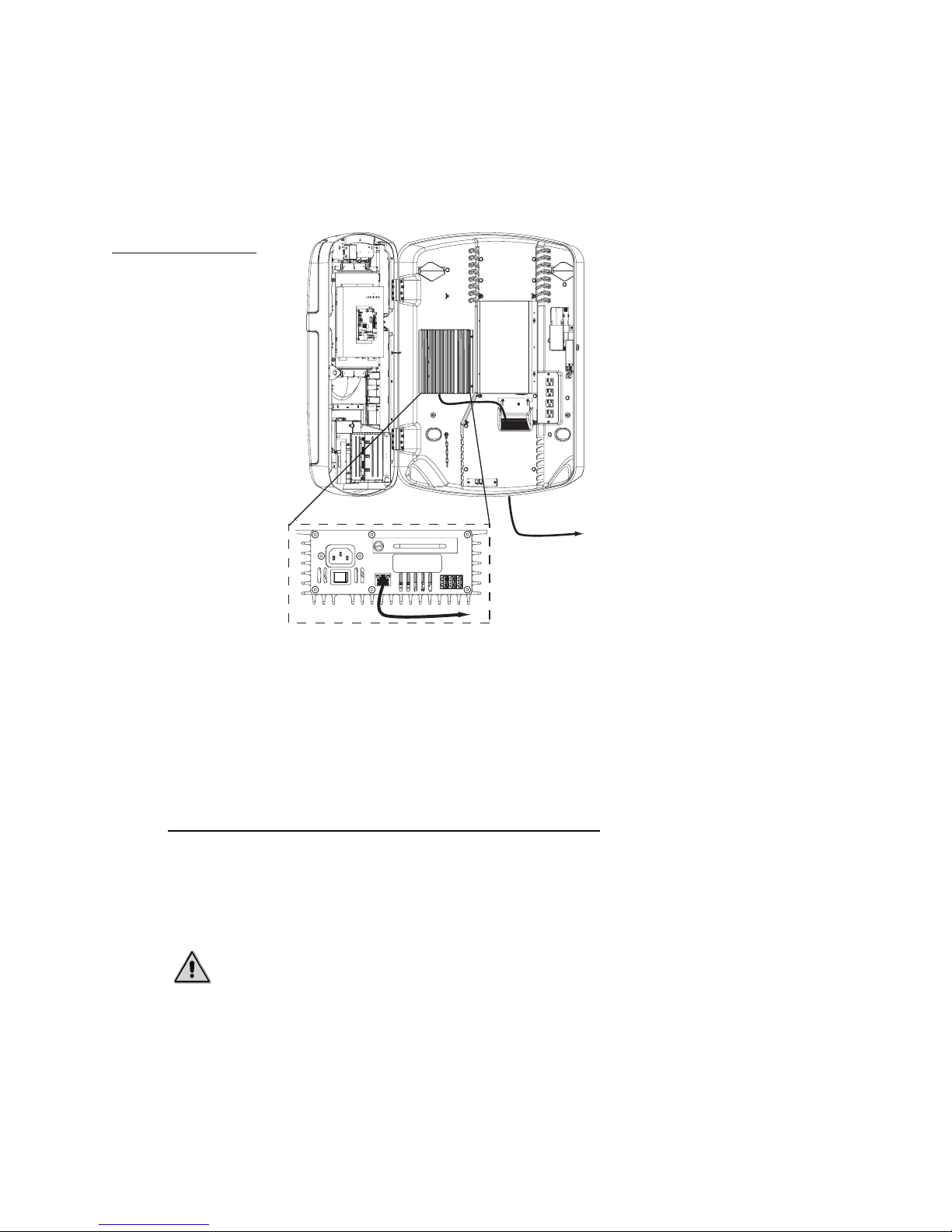
3. Route the free end of the cable in to the jukebox through the cable channel and then pass it
through the opening underneath the wire-relief strain bracket.
4. Connect the free end of the cable to the port labelled NETWORK on the bottom panel of the
MJS.
Figure 11
Connecting the Ovation
jukebox to a broadband
network
MJS Bottom View (enlarged)
NO USER SERVICEABLE PARTS INSIDE
50/60 Hz 2.0A MAX
100 - 120 VAC
NETWORK
ACT
ON OFF
LNK
t
o
R
Serial No.
USB
r
e
t
u
o
123
to
Router
The physical connection from the jukebox to the broadband network is now complete. You
will later configure the communications settings for the broadband network so the Ovation
can contact the TouchTunes server using this connection.
Tip: You can also set up a dial-up connection for a jukebox to provide redundancy in case of
communications problems with the broadband network. To set up this type of connection,
see “Connect the Ovation to the telephone network” below.
Connect the Ovation to the telephone network
You use the following procedures to attach the USB modem to the Ovation and then connect
the modem to the telephone network. The USB modem is required for establishing dial-up
connections between the jukebox and the TouchTunes server over the telephone network.
Caution: The MJS on your jukebox may have an open RJ-11 port marked TELCO. Do not
connect the telephone line to this port, as it is disabled on TouchTunes jukeboxes running
Gen 3 system software. Use the USB Modem to connect the jukebox to the telephone
network instead.
To install the USB modem in the jukebox:
1. Unpack the USB modem.
16
Page 23
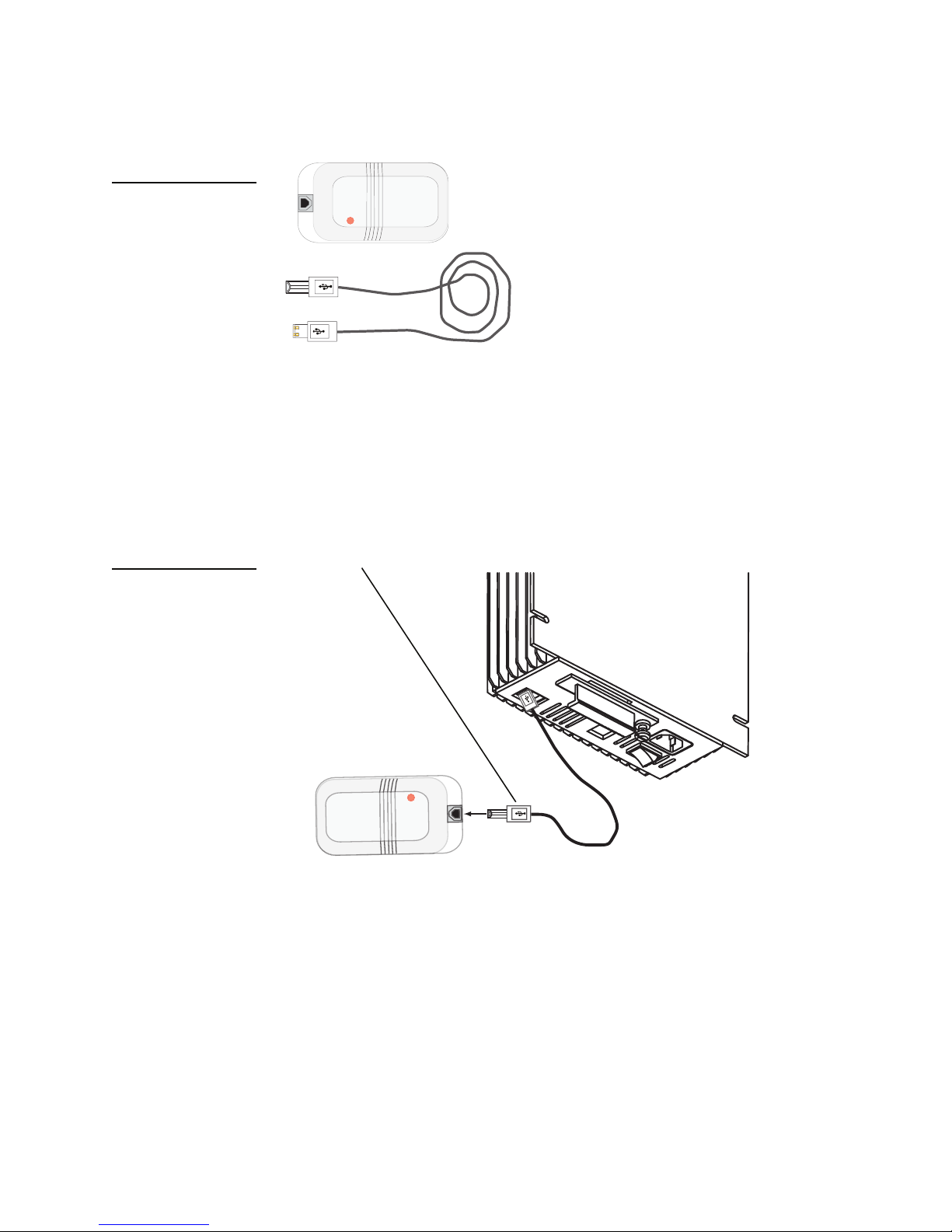
Figure 12
Connecting the Ovation to the Telephone or Broadband Network
The USB Modem includes a USB cable and the modem itself.
USB Modem and cable
Note: The USB modem is an optional jukebox component. If a USB modem was not included
with the jukebox, you must request it from your distributor or TouchTunes.
2. Connect the flat connector at one end of the USB cable to any of the USB ports on the bottom
panel of the MJS.
3. Connect the barrel-like connector (also called the B-Type connector) at other end of the USB
cable to its associated port on the USB modem.
Figure 13
Attaching the USB Modem
to the MJS
USB Modem
Radicom®
USB B-Type connector
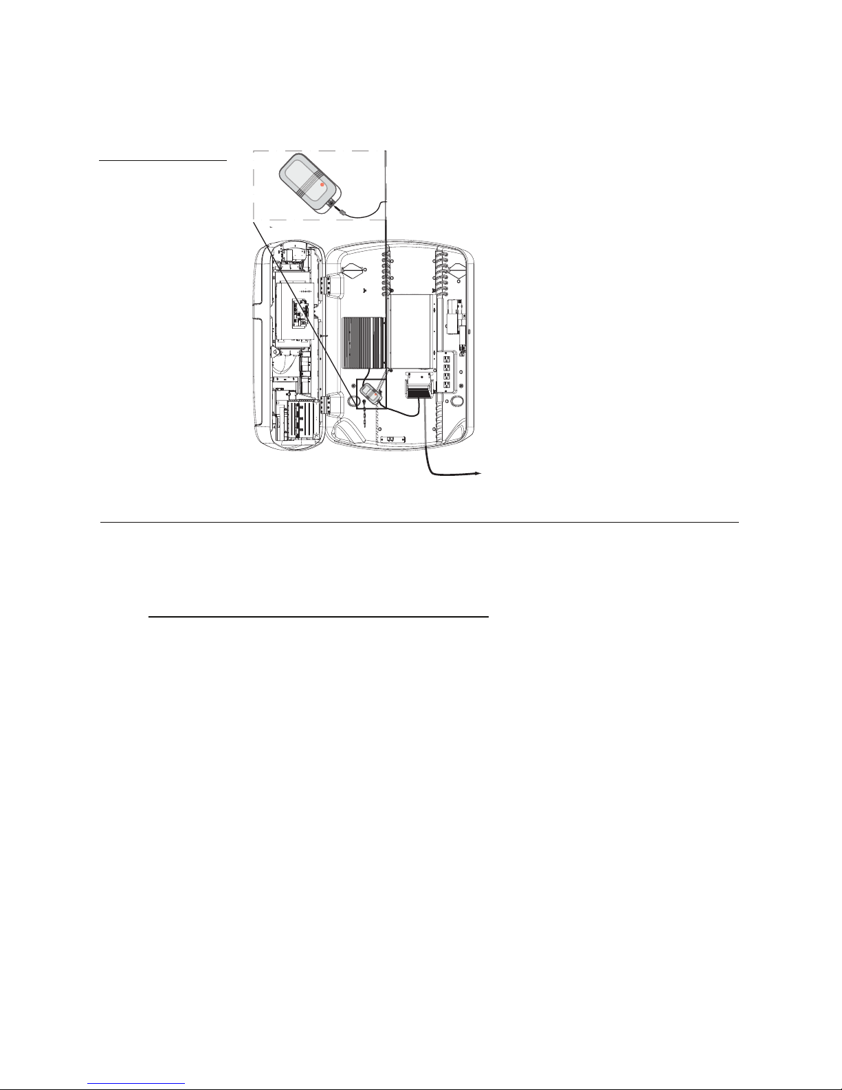
The modem is now installed. Next, connect a phone line to the USB modem so the Ovation
can access the telephone network.
To connect the jukebox to the telephone network:
1. Locate the phone line for the dial-up connection.
2. Attach one end of the phone line to the phone jack for the Ovation.
3. Route the free end of the phone line in to the jukebox through the cable channel and then
pass it through the opening underneath the wire-relief strain bracket.
Radicom®
USB Modem
17
Page 24
Installing the Ovation Jukebox
4. Connect the free end of the phone line to its associated port on the USB modem.
Figure 14
Connecting the phone line
Area Enlarged
U
SB
M
od
Radicom®
em
to the USB Modem
k
c
a
j
t
o
e
n
p
o
h
U
S
B
M
o
d
Rad
e
m
icom®
to
Phone Jack
Connecting Audio Speakers and Sources to the Ovation
In this sec tion, con nec t exte rna l spe ake rs a s we ll a s ex terna l au dio sou rces like mic rop hon es, T Vs
or CD/DVD players, to the Ovation.
18
Connect external speakers to the Ovation
By default, the Ovation does not include internal mounted speakers. Depending on the
configuration of your Ovation, you may have either of the following:
• An internally mounted TouchTunes DA415 amplifier with an external speaker system.
• An external Bose AM-141P Acoustimass amplifier and speaker system.
Refer to the supplied documentation for each system to connect these amplifier/speaker
systems to the Ovation:
• To connect the Bose Acoustimass system to the Ovation, see the Bose AM-141P Acoustimass
Speaker System Installation and Service Manual.
• To connect the TouchTunes DA415 amplifier to the Ovation, see the DA415 Amplifier Quick Start
Guide. (Document Part Number 900211-001)
Tip: These documents are also available from the TouchTunes Technical Support departments
as well as through the TouchTunes Dashboard.
Page 25

Connecting Power to the Ovation
In this section, connect the Ovation to the main AC power, close the jukebox and then turn it on
in order to activate it.
Connect the power cord to the Ovation
Components within the Ovation (such as the MJS and optional internal amplifier) are connected
to a main power-bar inside the case. You connect the power cord for this power bar to an
external AC power source to provide power to jukebox components.
To connect the power cord to the jukebox:
1. If necessary, locate the power cord for the jukebox.
The power cord for the Ovation is designed for a three-prong power outlet that is properly
grounded and polarized.
Connecting Power to the Ovation
Caution:
power outlets. If the power cord cannot plug into the intended AC power outlet, either find
another outlet or contact an electrician to replace the existing outlet with one that is
grounded and polarized.
Do not modify the supplied power cord to fit in ungrounded or unpolarized
2. Connect the male plug of the power cord to a properly grounded and polarized three-prong
power outlet.
Tighten the wire strength-relief bracket
All cables are now connected to the Ovation. You tighten the wire strength-relief bracket to
secure these cables before closing the Ovation.
To tighten the wire-strength relief bracket:
1. (Optional) Pull in and hold a short length (1 - 2 inches) of each cable running through the
cable channel to ensure all cables in the jukebox have some slack.
2. Using a screwdriver, loosen the screws for the wire-strain relief bracket so you can adjust the
bracket.
19
Page 26
Installing the Ovation Jukebox
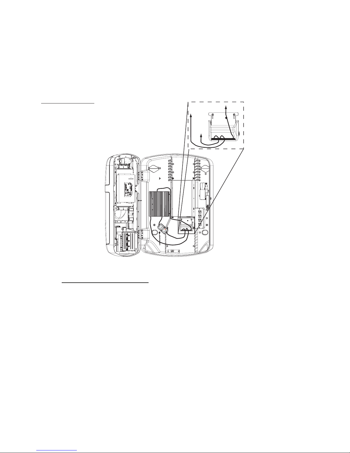
3. Adjust the wire-strain relief bracket until both of the following conditions are met:
• The bracket presses against and holding all of the cables coming into the jukebox through
the cable channel to maintain slack for each cable.
• The bracket partially closes the cable channel opening to the jukebox to prevent dust from
entering the Ovation.
Figure 15
Adjusting the wire strainrelief bracket to close the
cable channel
Area Enlarged
to Audio
to Power
Recepticle
to USB
Modem
U
S
B
M
od
Rad
e
m
icom®
Out
20
4. Tighten the screws for the wire-strain relief bracket to hold the bracket in position.
Turn on power to the MJS
You turn on power to the MJS in the Ovation so you can activate the jukebox and configure its
settings.
To turn on power to the MJS:
• Turn the MJS system power switch to ON.
The MJS in the jukebox powers up, checks the jukebox hardware components and then
begins loading its system software.
Page 27
Connecting Power to the Ovation
Close the Ovation case
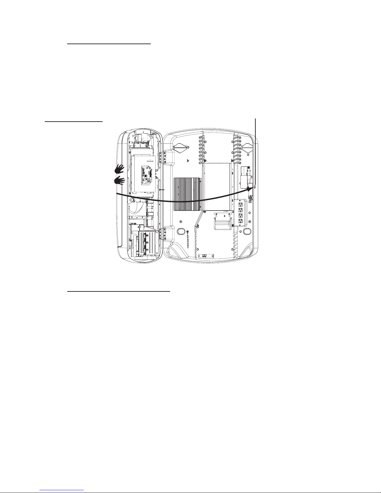
Once you have turned on the Ovation, close and lock its case.
To close the jukebox:
1. Close the Ovation case by gently swinging it shut and then pressing on its front face to
engage the locking mechanism.
Figure 16
Closing the Ovation
jukebox
2. Secure the Ovation by using the key to lock its case.
Lock
Activate the Ovation screen
When you power up a jukebox for the first time, it automatically goes into night mode: the MJS
and other internal components of the jukebox are running, but the touchscreen, audio system
and lights for the jukebox are disabled. Bring the jukebox out of night mode and activate its
screen before setting up the jukebox.
21
Page 28
Installing the Ovation Jukebox
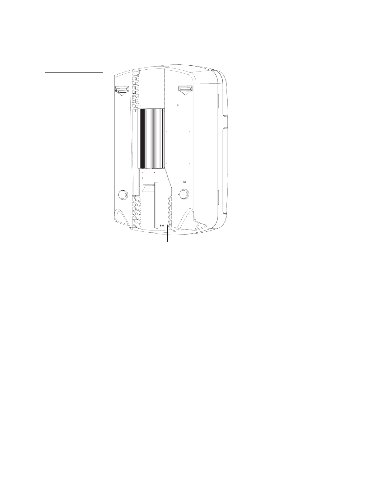
1. Press the Night Mode button on the rear of the jukebox.
Figure 17
Locating the Night Mode
button
Night Mode
button
Note: Buttons may be slightly recessed.
When you press this button, the touchscreen, lights and audio system for the jukebox are
activated. You can now use the touchscreen to activate the jukebox and configure its settings
using the system software.
2. Follow the procedure in “Activating the Jukebox” to configure and initiate communications
with the TouchTunes server and activate the jukebox.
22
Page 29

Activating the Jukebox
This section describes how to activate your TouchTunes Ovation jukebox after
you have completed the hardware installation.
Overview
The following installation features have been updated for the release of the TouchTunes Jukebox
Software, version 3.0:
• The installation process has been simplified and streamlined.
• Parts of the Diagnostic and Connectivity screens have been updated and combined into a new
Communication screen, which now features activity messages, network status LED indicators,
and network information.
• You no longer have to manually enter a jukebox password when you first start the jukebox as
this process has been automated. However, when necessary, you can now use the Manual
Override feature to register the jukebox while offline (when no internet connection is
available).
• The Offline Diagnostic Tool (ODT) has been simplified and given a graphical user interface.
Also note the following changes to the installation process:
• Currently, the TouchTunes jukebox may connect to the TouchTunes server via a broadband or
dial-up internet connection.
• Hardware testing procedures are not available during the installation process. You can,
however, use the ODT tool or test the jukeboxes’ various subsystems from the Operator
interface.
23
Page 30
Activating the Jukebox
Activation Procedure
In general, activation of your jukebox involves the steps listed in this section. Step-by-step
procedures are elaborated on in the rest of the document.
1. Power on the jukebox.
2. Proceed through the installation screens:
Power on the Jukebox
1. Power on the Modular Jukebox System (MJS) by pressing the On/Off switch on the connector
panel of the MJS unit.
The STBY light (standby) turns on in the control board to indicate that the jukebox can be
turned on.
WARNING: During the following procedures, there may be periods during which
the jukebox appears not to be responding.
Booting the system with the new Gen 3 hard drive may take up to ten (10) minutes,
and the screen may be blank for up to 90 seconds during the installation procedure.
It is extremely important that you do not power down or attempt to reboot the
jukebox during this procedure, or you will risk corrupting and rendering the
hard drive unusable.
2. Power on the jukebox by pressing the Power On button on the control board.
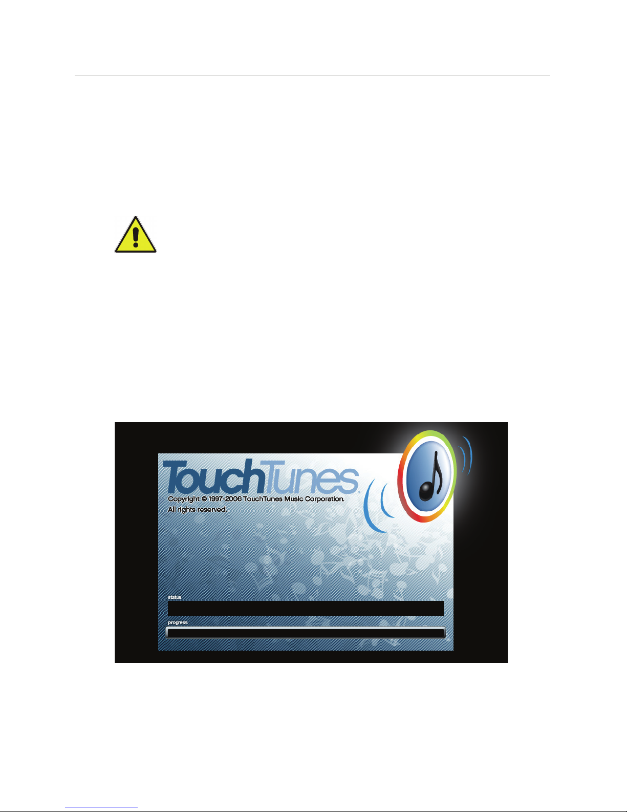
The Jukebox Software initialization screen appears indicating that the jukebox is starting the
installation process.
Jukebox Software Initialization Screen
Configure the Jukebox
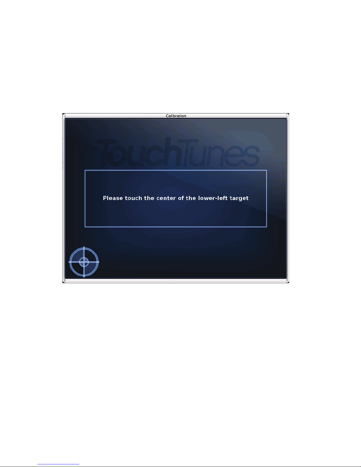
After the jukebox has initialized, the Calibration screen appears.
24
Page 31
Activation Procedure
Note: If there is a corruption in the jukebox’s iButton or other serious error, the Calibration
screen will not appear but rather an error will be indicated. See “Encountering a Serious System
Error” on page 16.
Calibrate the Touchscreen as Required
1. Touch the center of the target that appears on the upper-left of the screen.
2. Touch the center of the target that appears on the lower-right of the screen.
3. Touch the center of the target that appears on the lower-left of the screen.
Calibration Screen
The Settings screen appears.
Select Settings to Use
In the Settings screen, you select where to get the jukebox settings from. Settings include mixer
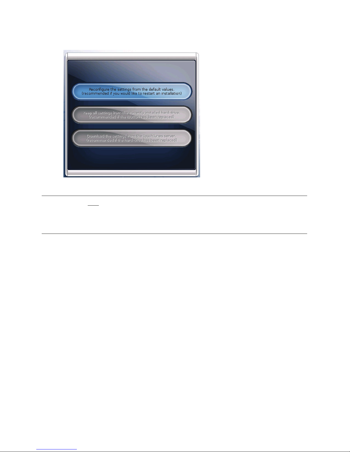
levels, credit rules, the remote ID, and the other configurable options available from the
Operator interface or via the TouchTunes Dashboard.
25
Page 32
Activating the Jukebox
1. Touch one of the following:
Settings Screen
Note: For new Gen 3 jukeboxes, the only available option is the first one—the second and third
options are provided for cases where the hard drive has been replaced, such as when migrating
from previous-generation to Gen 3 software. When an option is not available, it is grayed out and
cannot be selected.
• Reconfigure the settings from the default values: Touch to reset all setting values to the
factory defaults. When installing the Jukebox Software on a jukebox with a new iButton and
hard-drive, this is the only option available.
• Keep all settings from the currently installed hard-drive: Touch to preserve the settings
from the hard-drive. For example, use this option if you replaced the iButton, or if you are
swapping in a hard-drive onto which software has been previously installed. In both these
cases the jukebox detects a hardware change, and can retrieve the settings from the hard-drive.
This option is not available if you have installed a new hard-drive into the jukebox.
• Download the settings from the TouchTunes server: Touch to retrieve the settings from the
TouchTunes server. For example, use this option on a jukebox where the software has been
previously installed, where the iButton stays in place, but a new hard-drive is swapped in. In this
case the jukebox retrieves the settings for the jukebox corresponding to the identification
number in the iButton This option is not available if a new iButton has been installed on the
jukebox.
OPTIONAL: Go Back to the Settings Screen
2. If you chose the Keep all settings from the currently installed hard-drive or Download the
settings from the TouchTunes server options in the Settings screen, the BACK button is
available in the Communication screen that appears. You can touch the BACK button to
26
Page 33
Activation Procedure
return to the Settings screen. You might do this, for example, if you decide to reset the
settings to factory defaults instead of keeping the hard-drive settings.
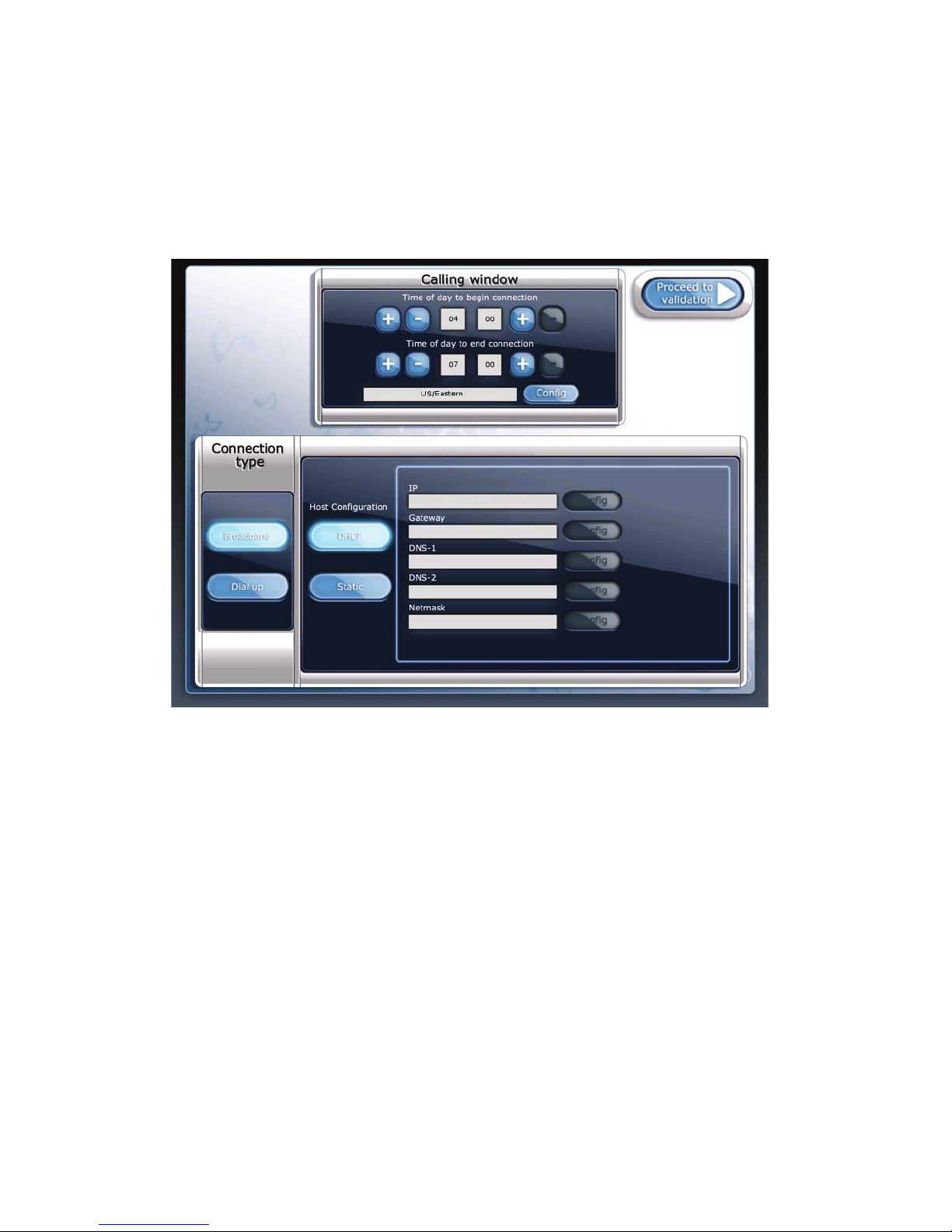
Choose the Calling Window and Connection Type
Once you have selected your settings, the Calling Window and Connection Type screen
displays, enabling you to select the times and type of connection the jukebox will use to
communicate with the TouchTunes server.
Calling Window and Connection Type
The Calling window controls allow you to specify the nightly time range during which the
jukebox will communicate with the TouchTunes server. Use the corresponding plus (+) and
minus (-) buttons to specify the starting and ending times for communication.
• Time of day to begin connection: Set this to one half hour after the location is locked up for
the night (i.e., the time the last person leaves and locks the front door). The half hour gives you
a buffer in case things are running late one night.
• Time of day to end communication: Set this to one half hour before the earliest person arrives
and enters the location.
27
Page 34
Activating the Jukebox
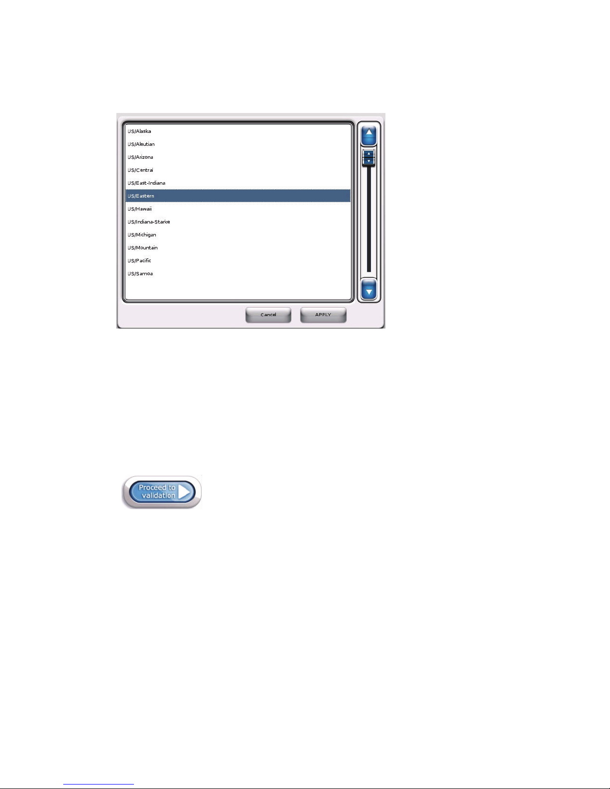
• Config: Use this button to display a scrolled window (as shown below) from which you can
select the location’s time zone. Use the scrolling controls to move up and down through the list,
touch a time zone to select it, and then press APPLY.
Time Zone Selection
The Connection type controls allow you to choose the type of network connection for the
jukebox. Depending on your selection, different settings will display in the lower area of the
screen, allowing you to specify connection parameters.
To choose a dynamic (DHCP) broadband connection:
1. Select DHCP to obtain an IP address automatically from the ISP or the location’s router.
2. Touch Proceed to Validation at the upper right-hand area of the screen to proceed to the
Communications screen.
Proceed to validation
To choose a static broadband connection:
1. Select Static to assign a static IP address, and then enter all configuration parameters as
supplied by the ISP.
The screen refreshes, with all Config buttons enabled to allow you to enter the required
information.
2. Select the Config button associated with the IP field.
28
Page 35
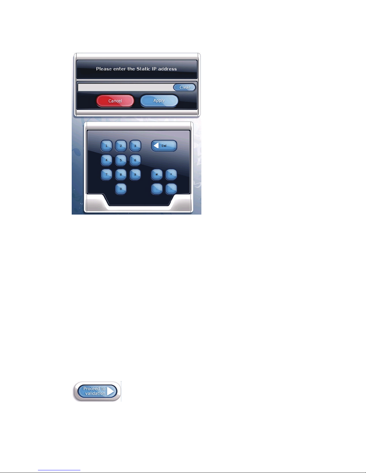
A window with a numeric keypad displays.
Activation Procedure
Static IP Address Configuration Window
3. Using the keypad, type in the static IP address supplied by the ISP.
Note: The pound (#), asterisk (*), and minus (-) keys are used for entering dial-up information
only, and are not used when entering data for a broadband connection.
• Use the period (.) key to delimit the individual fields of the IP address.
• If you make a mistake, use the Del key to erase the input, and then re-enter the correct
information.
• Use the Clear key to erase the entire contents of the IP address field.
• Use the Cancel key to cancel the operation and return to the Calling Window and
Connection Type screen.
4. When you have finished entering the IP address, press Apply.
5. Enter the Gateway, DNS-1, DNS-2, and Netmask information supplied by the ISP by using
the associated Config buttons and numeric keypad windows.
6. When you have entered information in all the required fields, touch Proceed to validation at
the upper right-hand area of the Calling Window and Connection Type screen to proceed to
the Communications screen.
Proceed to validation
29
Page 36
Activating the Jukebox
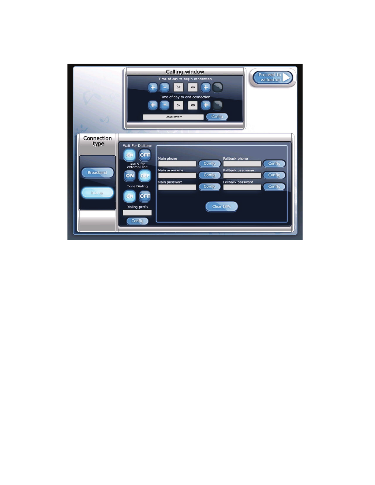
To choose a dial-up connection:
Refer to the following figure when setting up your dial-up Internet connection.
Dial-up Connection Settings
1. Disable the Wait For Dialtone option if the location has a voice mail service installed on its
line.
When this option is disabled, the jukebox will not check for a dial tone before dialing out,
instead it will pause for two seconds then begin dialing.
2. Enable the Dial 9 for external line option if you need to dial 9 to access an external line, for
example, if a PBX is installed at the location.
3. Turn the Tone D ial i ng option off if the location uses pulse dialing.
4. If you need to dial an outgoing prefix before the phone number, touch the Config button for
Dialing prefix, then use the numeric keypad to enter the prefix.
If the location has call waiting, you should enter the prefix to disable it. In most cases this is
*70. You may need to add a pause to the end of this sequence, as sometimes there is a delay
before the dial tone returns. Use the # key to enter a pause. For example, the sequence *70##
disables call waiting and then pauses twice before continuing to dial.
5. Touch the Config button associated with the Main phone field to specify the phone number
of your ISP. The jukebox will use number first to attempt communication with the TouchTunes
server.
30
Page 37
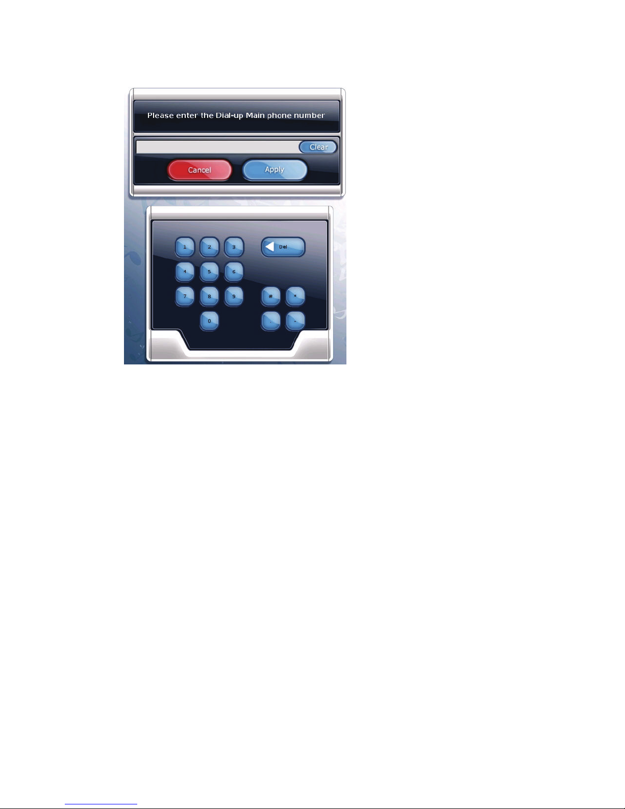
A window with a numeric keypad displays.
Activation Procedure
Main Phone Number Configuration Window.
6. Using the keypad, type in the phone number supplied by the ISP.
• If you make a mistake, use the Del key to erase the input, and then re-enter the correct
information.
• Use the Clear key to erase the entire contents of the main phone number field.
• Use the Cancel key to cancel the operation and return to the Calling Window and
Connection Type screen.
7. When you have finished entering the main phone number, press Apply.
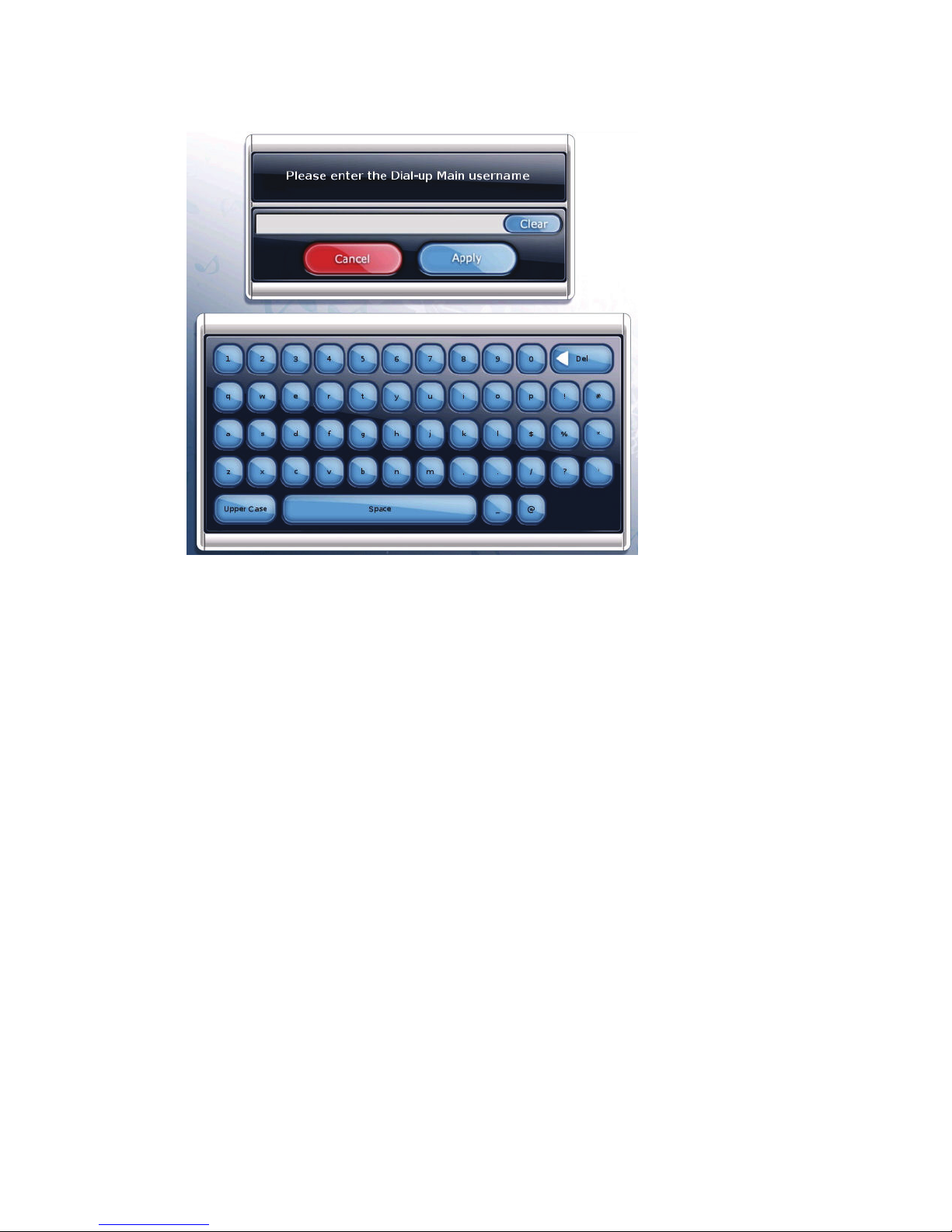
8. Touch the Config button associated with the Main username field to specify the user name
associated with the main phone number.
31
Page 38
Activating the Jukebox
A window with an alphanumeric keypad displays.
Main Username Configuration Window
9. Using the keypad, type in the main username supplied by the ISP.
• If you make a mistake, use the Del key to erase the input, and then re-enter the correct
information.
• Use the Clear key to erase the entire contents of the main username field.
• Use the Cancel key to cancel the operation and return to the Calling Window and
Connection Type screen.
10.When you have finished entering the main phone number, press Apply.
11.Touch the Config button associated with the Main password field to specify the password
associated with the main username and phone number.
12.Use the alphanumeric keypad to enter the password, then press Apply.
13.Use the Fallback phone/username/password fields to specify a secondary set of
configuration settings in the event that communication using the main phone/username/
password is unsuccessful.
To enter values for these settings, touch the associated CONFIG
button, then use the numeric
or alphanumeric keypad to enter the information in the same manner as you did for main
phone/username/password fields.
32
Page 39
Activation Procedure
14.Touch Proceed to Validation at the upper right-hand area of the Calling Window and
Connection Type screen to proceed to the Communications screen.
Touch to continue
Monitor the Communication Screen
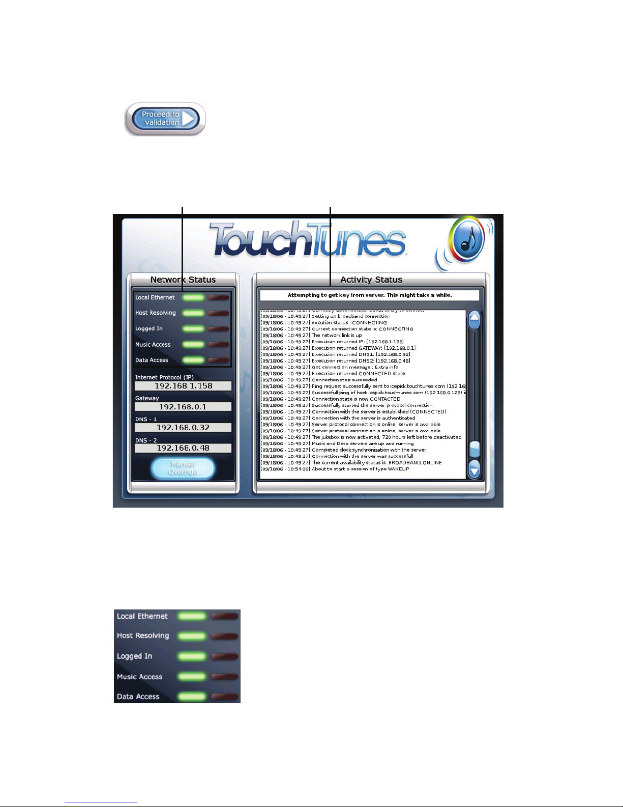
1. Monitor the Communication screen that appears:
a
b
Communication Screen a. Network status LED indicators b. Activity messages
The Communication screen indicates the progress of the jukebox as it attempts to
communicate with the TouchTunes server. Network status LED indicators display the success
or failure of each communication step, with corresponding information appearing in the
Activity messages.
2. Monitor the Network status LED indicators:
Network Status LED Indicators
33
Page 40
Activating the Jukebox
For installation and activation, the jukebox needs the Logged In, Music Access and Data Access
LED indicators to be green. There may be cases where one of the access types is offline. After
activation, the jukebox will still function if one of these is offline, but there may be some
temporary reduced functionality. For example, if there is maintenance being performed to the
TouchTunes Dashboard on the TouchTunes server, data access may be offline. In this case, the
jukebox will still be able to receive new music, but any settings you make for it via the
TouchTunes Dashboard will not be registered on the jukebox until data access is restored.
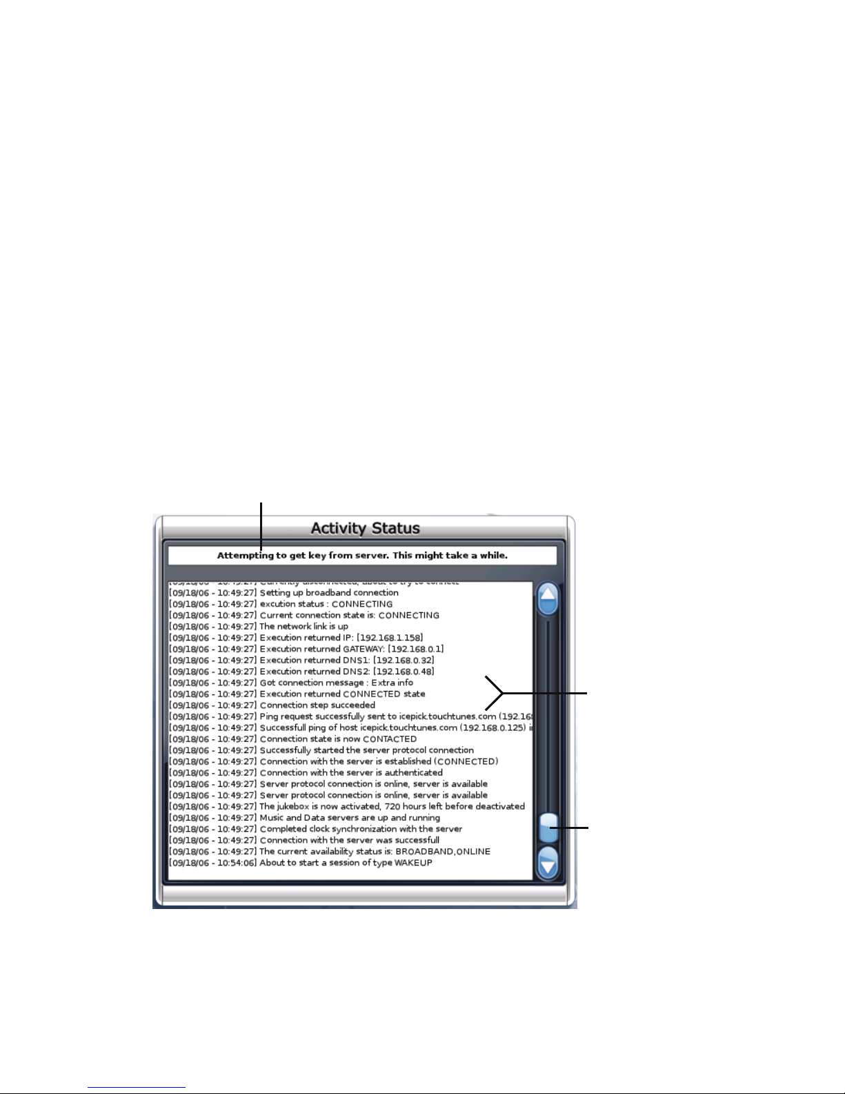
3. Verify the information in the Activity messages:
• Local Ethernet: Indicates whether an ethernet cable is properly connected to the jukebox,
and the jukebox is receiving a signal from it.
• Host Resolving: Indicates whether the jukebox is connected to the internet.
• Logged In: Indicates whether the jukebox is logged into the TouchTunes server. The jukebox
mus t be able to log in to the To uchTunes server to rece ive ac ti vat ion info rmatio n and per for m
transactions, such as returning daily sales information.
• Music Access: Indicates whether the jukebox can access music from the TouchTunes server.
The jukebox must have music access to download new songs.
• Data Access: Indicates whether the jukebox can communicate with TouchTunes server to
receive updates from the TouchTunes Dashboard. The jukebox must have data access to
receive any new settings you may have made to it via the TouchTunes Dashboard.
a
a. Current main activity is indicated b. Complete activity log is indicated c. Scroll bar
If necessary, do one of the following:
• To scroll the Activity Status window, drag the scroll bar up or down.
34
b
c
Page 41

• To scroll up in the Activity Status window, touch the button.
• To scroll down in the Activity Status window, touch the button.
When the jukebox is fully initialized, the Attract Screen of the Customer Interface displays.
Error Scenarios
During installation, errors could occur if there has been damage to the jukebox hardware, or
corruptions in its software. Under normal circumstances, these should be rare.
The following are a couple of the error scenarios which could occur.
Encountering a Corruption in the iButton or Hard-Drive
A corruption in the iButton or hard-drive could result in the jukebox being unable to play songs
on the hard-drive. In this case, the jukebox must download some information from the
TouchTunes server to fix the problem. When the jukebox is started, the Communication screen
appears indicating it is downloading the required file, and then boots into the Customer
interface.
Encountering a Serious System Error
Under serious conditions—whether major system problems with hardware or software—an
error screen appears upon jukebox initialization indicating that you should contact TouchTunes,
as no other action can be taken. See “Contacting Technical Support” on page 2.
Error Scenarios
35
Page 42

Activating the Jukebox
36
Page 43

Disclaimer
Document Part Number: 900209-001(March 2007)
TouchTunes and the TouchTunes logo are trademarks of TouchTunes Music Corporation.
Bose and Acoustimass are registered trademarks of Bose Corporation.
All other brand and product names are trademarks or registered trademarks of their respective
corporations.
The mention of any product does not constitute an endorsement by TouchTunes Music Corporation.
This manual is furnished under a lease agreement and may only be copied or used within accordance
with the terms of such lease agreement. The content of this manual is furnished for informational use
only, is subject to change without notice, and should not be construed as a commitment by
TouchTunes Music Corporation. TouchTunes Music Corporation assumes no responsibility or liability
for any errors or inaccuracies that may appear in this document.
Except as permitted by such lease agreement, no part of this publication may be reproduced, stored
in any retrieval system, or transmitted, in any form or by any means, electronic, mechanical,
recording, or otherwise, without prior written consent of TouchTunes Music Corporation.
Changes are periodically made to the information herein; these changes will be incorporated into
new editions of this publication. TouchTunes may make improvements and/or changes in the
products and/or software programs described in this publication at any time.
If you have comments on this manual or the products it describes, address them to:
TouchTunes Music Corporation
Attention: Publications
3 Commerce Place, 4
Montreal, Quebec, Canada H3E 1H7
Telephone: 1-888-338-JUKE
Support hotline: 1-888-711-JUKE
Fax: (847) 419-3304
TouchTunes may use or distribute whatever information you supply in any way it believes
appropriate without incurring any obligations to you.
Copyright © 2007 TouchTunes Music Corporation. All rights reserved, including those to reproduce
this publication or parts thereof in any form without permission in writing from TouchTunes Music
Corporation.
th
Floor
 Loading...