

TouchTunes Allegro MX-1v Installation And Setup Manual


Disclaimer
Document Part Number: 900375-001 Rev. 03 (February 2012)
TouchTunes, Allegro MX-1v, and the TouchTunes logo are trademarks of TouchTunes Interactive
Networks.
All other brand and product names are trademarks or registered trademarks of their respective
corporations.
The mention of any product does not constitute an endorsement by TouchTunes Interactive
Networks.
This manual is furnished under a lease agreement and may only be copied or used within
accordance with the terms of such lease agreement. The content of this manual is furnished for
informational use only, is subject to change without notice, and should not be construed as a
commitment by TouchTunes Interactive Networks. TouchTunes Interactive Networks assumes
no responsibility or liability for any errors or inaccuracies that may appear in this document.
Except as permitted by such lease agreement, no part of this publication may be reproduced,
stored in any retrieval system, or transmitted, in any form or by any means, electronic,
mechanical, recording, or otherwise, without prior written consent of TouchTunes Interactive
Networks.
Changes are periodically made to the information herein; these changes will be incorporated
into new editions of this publication. TouchTunes may make improvements and/or changes in
the products and/or software programs described in this publication at any time.
If you have comments on this manual or the products it describes, address them to:
TouchTunes Interactive Networks
Attention: Publications
400 Sainte-Croix Avenue, Suite 200 E
Montreal, Quebec, Canada H4N 3L4
Telephone: 1-847-419-3300
Fax: (847) 419-3304
TouchTunes may use or distribute whatever information you supply in any way it believes
appropriate without incurring any obligations to you.
Copyright © 2010 TouchTunes Interactive Networks. All rights reserved, including those to
reproduce this publication or parts thereof in any form without permission in writing from
TouchTunes Interactive Networks.

1 Introduction 1
About this guide. . . . . . . . . . . . . . . . . . . . . . . . . . . . . . . . . . . . . . . . . . . . . . . . . . . . . . . . . . . . . . . . . . . . . . . . . . . . . . . . . . . . . . . . . . . . . 1
Related Documentation . . . . . . . . . . . . . . . . . . . . . . . . . . . . . . . . . . . . . . . . . . . . . . . . . . . . . . . . . . . . . . . . . . . . . . . . . . . . . . . . . . . . . 1
Writing Conventions. . . . . . . . . . . . . . . . . . . . . . . . . . . . . . . . . . . . . . . . . . . . . . . . . . . . . . . . . . . . . . . . . . . . . . . . . . . . . . . . . . . . . . . . . 2
Important Safety Information . . . . . . . . . . . . . . . . . . . . . . . . . . . . . . . . . . . . . . . . . . . . . . . . . . . . . . . . . . . . . . . . . . . . . . . . . . . . . . . . 2
Contacting TouchTunes . . . . . . . . . . . . . . . . . . . . . . . . . . . . . . . . . . . . . . . . . . . . . . . . . . . . . . . . . . . . . . . . . . . . . . . . . . . . . . . . . . . . . 4
2 Allegro MX-1: An Overview 5
Introducing Allegro MX-1 . . . . . . . . . . . . . . . . . . . . . . . . . . . . . . . . . . . . . . . . . . . . . . . . . . . . . . . . . . . . . . . . . . . . . . . . . . . . . . . . . . . . 5
Components and Features. . . . . . . . . . . . . . . . . . . . . . . . . . . . . . . . . . . . . . . . . . . . . . . . . . . . . . . . . . . . . . . . . . . . . . . . . . . . . . . . . . . 6
Sound . . . . . . . . . . . . . . . . . . . . . . . . . . . . . . . . . . . . . . . . . . . . . . . . . . . . . . . . . . . . . . . . . . . . . . . . . . . . . . . . . . . . . . . . . . . . . . . . . . 6
Touch-screen Monitor . . . . . . . . . . . . . . . . . . . . . . . . . . . . . . . . . . . . . . . . . . . . . . . . . . . . . . . . . . . . . . . . . . . . . . . . . . . . . . . . . . 7
Cabinet. . . . . . . . . . . . . . . . . . . . . . . . . . . . . . . . . . . . . . . . . . . . . . . . . . . . . . . . . . . . . . . . . . . . . . . . . . . . . . . . . . . . . . . . . . . . . . . . . 7
Door . . . . . . . . . . . . . . . . . . . . . . . . . . . . . . . . . . . . . . . . . . . . . . . . . . . . . . . . . . . . . . . . . . . . . . . . . . . . . . . . . . . . . . . . . . . . . . . . . . . 7
Payment Means . . . . . . . . . . . . . . . . . . . . . . . . . . . . . . . . . . . . . . . . . . . . . . . . . . . . . . . . . . . . . . . . . . . . . . . . . . . . . . . . . . . . . . . . 7
Remote Controls. . . . . . . . . . . . . . . . . . . . . . . . . . . . . . . . . . . . . . . . . . . . . . . . . . . . . . . . . . . . . . . . . . . . . . . . . . . . . . . . . . . . . . . .8
Lightshow . . . . . . . . . . . . . . . . . . . . . . . . . . . . . . . . . . . . . . . . . . . . . . . . . . . . . . . . . . . . . . . . . . . . . . . . . . . . . . . . . . . . . . . . . . . . . . 8
Poster Frame . . . . . . . . . . . . . . . . . . . . . . . . . . . . . . . . . . . . . . . . . . . . . . . . . . . . . . . . . . . . . . . . . . . . . . . . . . . . . . . . . . . . . . . . . . . 8
System . . . . . . . . . . . . . . . . . . . . . . . . . . . . . . . . . . . . . . . . . . . . . . . . . . . . . . . . . . . . . . . . . . . . . . . . . . . . . . . . . . . . . . . . . . . . . . . . . 8
Amplifier Overview . . . . . . . . . . . . . . . . . . . . . . . . . . . . . . . . . . . . . . . . . . . . . . . . . . . . . . . . . . . . . . . . . . . . . . . . . . . . . . . . . . . . . . . . . . 8
JCB Computer Overview . . . . . . . . . . . . . . . . . . . . . . . . . . . . . . . . . . . . . . . . . . . . . . . . . . . . . . . . . . . . . . . . . . . . . . . . . . . . . . . . . . . . . 10
Accessing Components. . . . . . . . . . . . . . . . . . . . . . . . . . . . . . . . . . . . . . . . . . . . . . . . . . . . . . . . . . . . . . . . . . . . . . . . . . . . . . . . . . . . . . 11
Opening the Main Enclosure . . . . . . . . . . . . . . . . . . . . . . . . . . . . . . . . . . . . . . . . . . . . . . . . . . . . . . . . . . . . . . . . . . . . . . . . . . . .11
Accessing the Service Tray . . . . . . . . . . . . . . . . . . . . . . . . . . . . . . . . . . . . . . . . . . . . . . . . . . . . . . . . . . . . . . . . . . . . . . . . . . . . . . 12
Service Light. . . . . . . . . . . . . . . . . . . . . . . . . . . . . . . . . . . . . . . . . . . . . . . . . . . . . . . . . . . . . . . . . . . . . . . . . . . . . . . . . . . . . . . . . . . . 16
Accessing the Rear of Monitor. . . . . . . . . . . . . . . . . . . . . . . . . . . . . . . . . . . . . . . . . . . . . . . . . . . . . . . . . . . . . . . . . . . . . . . . . . . 16

Transporting Allegro MX-1 . . . . . . . . . . . . . . . . . . . . . . . . . . . . . . . . . . . . . . . . . . . . . . . . . . . . . . . . . . . . . . . . . . . . . . . . . . . . . . . . . . . 18
3 Pre-Installation 23
Unpacking and Checking Jukebox Components . . . . . . . . . . . . . . . . . . . . . . . . . . . . . . . . . . . . . . . . . . . . . . . . . . . . . . . . . . . . . . 23
Setting Up a Broadband Connection . . . . . . . . . . . . . . . . . . . . . . . . . . . . . . . . . . . . . . . . . . . . . . . . . . . . . . . . . . . . . . . . . . . . . . . . . 24
Preparing Tools for Installation. . . . . . . . . . . . . . . . . . . . . . . . . . . . . . . . . . . . . . . . . . . . . . . . . . . . . . . . . . . . . . . . . . . . . . . . . . . . . . . 25
4 Installing the Allegro MX-1 Jukebox 27
Installing the Allegro MX-1 Jukebox . . . . . . . . . . . . . . . . . . . . . . . . . . . . . . . . . . . . . . . . . . . . . . . . . . . . . . . . . . . . . . . . . . . . . . . . . .27
Replacing the Lock for the Allegro MX-1. . . . . . . . . . . . . . . . . . . . . . . . . . . . . . . . . . . . . . . . . . . . . . . . . . . . . . . . . . . . . . . . . . . . . . 29
Installing the Hard Drive . . . . . . . . . . . . . . . . . . . . . . . . . . . . . . . . . . . . . . . . . . . . . . . . . . . . . . . . . . . . . . . . . . . . . . . . . . . . . . . . . . . . . 30
Connecting the Allegro MX-1 to the Broadband Network . . . . . . . . . . . . . . . . . . . . . . . . . . . . . . . . . . . . . . . . . . . . . . . . . . . . . 33
Connecting Audio Speakers to the Allegro MX-1. . . . . . . . . . . . . . . . . . . . . . . . . . . . . . . . . . . . . . . . . . . . . . . . . . . . . . . . . . . . . . 35
Connecting the Supplied External Satellite Speakers . . . . . . . . . . . . . . . . . . . . . . . . . . . . . . . . . . . . . . . . . . . . . . . . . . . . . 37
Speaker Wiring Guide for Additional Speakers . . . . . . . . . . . . . . . . . . . . . . . . . . . . . . . . . . . . . . . . . . . . . . . . . . . . . . . . . . . 39
Connecting Audio Zones 2 and 3 . . . . . . . . . . . . . . . . . . . . . . . . . . . . . . . . . . . . . . . . . . . . . . . . . . . . . . . . . . . . . . . . . . . . . . . . 40
Connecting Power to the Allegro MX-1 . . . . . . . . . . . . . . . . . . . . . . . . . . . . . . . . . . . . . . . . . . . . . . . . . . . . . . . . . . . . . . . . . . . . . . . 41
Tightening the Wire Strain-relief Sliders . . . . . . . . . . . . . . . . . . . . . . . . . . . . . . . . . . . . . . . . . . . . . . . . . . . . . . . . . . . . . . . . . 42
Closing the Allegro MX-1 Case . . . . . . . . . . . . . . . . . . . . . . . . . . . . . . . . . . . . . . . . . . . . . . . . . . . . . . . . . . . . . . . . . . . . . . . . . . 43
Activating the Allegro MX-1 Screen. . . . . . . . . . . . . . . . . . . . . . . . . . . . . . . . . . . . . . . . . . . . . . . . . . . . . . . . . . . . . . . . . . . . . . 44
5Activating the Jukebox 45
Activation Procedure . . . . . . . . . . . . . . . . . . . . . . . . . . . . . . . . . . . . . . . . . . . . . . . . . . . . . . . . . . . . . . . . . . . . . . . . . . . . . . . . . . . . . . . . 45
Power on the Jukebox . . . . . . . . . . . . . . . . . . . . . . . . . . . . . . . . . . . . . . . . . . . . . . . . . . . . . . . . . . . . . . . . . . . . . . . . . . . . . . . . . . 45
Configure the Jukebox . . . . . . . . . . . . . . . . . . . . . . . . . . . . . . . . . . . . . . . . . . . . . . . . . . . . . . . . . . . . . . . . . . . . . . . . . . . . . . . . . . 46
Error Scenarios . . . . . . . . . . . . . . . . . . . . . . . . . . . . . . . . . . . . . . . . . . . . . . . . . . . . . . . . . . . . . . . . . . . . . . . . . . . . . . . . . . . . . . . . . . . . . .54
Encountering a Corruption in the ID Chip or Hard-Drive . . . . . . . . . . . . . . . . . . . . . . . . . . . . . . . . . . . . . . . . . . . . . . . . . . 54
Encountering a Serious System Error . . . . . . . . . . . . . . . . . . . . . . . . . . . . . . . . . . . . . . . . . . . . . . . . . . . . . . . . . . . . . . . . . . . . 55
6 Post-installation 57
Activating the Operator Interface . . . . . . . . . . . . . . . . . . . . . . . . . . . . . . . . . . . . . . . . . . . . . . . . . . . . . . . . . . . . . . . . . . . . . . . . . . . . 57
Setting Up the Remote Control . . . . . . . . . . . . . . . . . . . . . . . . . . . . . . . . . . . . . . . . . . . . . . . . . . . . . . . . . . . . . . . . . . . . . . . . . . . . . . 59
Setting the Remote Control ID . . . . . . . . . . . . . . . . . . . . . . . . . . . . . . . . . . . . . . . . . . . . . . . . . . . . . . . . . . . . . . . . . . . . . . . . . . 59
Learning the Remote ID. . . . . . . . . . . . . . . . . . . . . . . . . . . . . . . . . . . . . . . . . . . . . . . . . . . . . . . . . . . . . . . . . . . . . . . . . . . . . . . . . 60
Key Assignments and Functionality. . . . . . . . . . . . . . . . . . . . . . . . . . . . . . . . . . . . . . . . . . . . . . . . . . . . . . . . . . . . . . . . . . . . . . 61
Configuring the Bill Acceptor(s) . . . . . . . . . . . . . . . . . . . . . . . . . . . . . . . . . . . . . . . . . . . . . . . . . . . . . . . . . . . . . . . . . . . . . . . . . . . . . . 63
Testing the Payment Acceptors . . . . . . . . . . . . . . . . . . . . . . . . . . . . . . . . . . . . . . . . . . . . . . . . . . . . . . . . . . . . . . . . . . . . . . . . . . . . . . 63
Testing the Bill and Coin Acceptors. . . . . . . . . . . . . . . . . . . . . . . . . . . . . . . . . . . . . . . . . . . . . . . . . . . . . . . . . . . . . . . . . . . . . . 64
Testing the Credit Card Reader . . . . . . . . . . . . . . . . . . . . . . . . . . . . . . . . . . . . . . . . . . . . . . . . . . . . . . . . . . . . . . . . . . . . . . . . . . 65
Changing the Front Panel Poster . . . . . . . . . . . . . . . . . . . . . . . . . . . . . . . . . . . . . . . . . . . . . . . . . . . . . . . . . . . . . . . . . . . . . . . . . . . . .67
Adjusting Monitor Brightness/Contrast. . . . . . . . . . . . . . . . . . . . . . . . . . . . . . . . . . . . . . . . . . . . . . . . . . . . . . . . . . . . . . . . . . . . . . . 68
Enabling DSP Equalization . . . . . . . . . . . . . . . . . . . . . . . . . . . . . . . . . . . . . . . . . . . . . . . . . . . . . . . . . . . . . . . . . . . . . . . . . . . . . . . . . . . 70
Connecting an External Audio Source . . . . . . . . . . . . . . . . . . . . . . . . . . . . . . . . . . . . . . . . . . . . . . . . . . . . . . . . . . . . . . . . . . . . . . . . 71
Requirements . . . . . . . . . . . . . . . . . . . . . . . . . . . . . . . . . . . . . . . . . . . . . . . . . . . . . . . . . . . . . . . . . . . . . . . . . . . . . . . . . . . . . . . . . . 71
Procedure . . . . . . . . . . . . . . . . . . . . . . . . . . . . . . . . . . . . . . . . . . . . . . . . . . . . . . . . . . . . . . . . . . . . . . . . . . . . . . . . . . . . . . . . . . . . . . 72
Connecting a Microphone . . . . . . . . . . . . . . . . . . . . . . . . . . . . . . . . . . . . . . . . . . . . . . . . . . . . . . . . . . . . . . . . . . . . . . . . . . . . . . . . . . .73
Requirements . . . . . . . . . . . . . . . . . . . . . . . . . . . . . . . . . . . . . . . . . . . . . . . . . . . . . . . . . . . . . . . . . . . . . . . . . . . . . . . . . . . . . . . . . . 73
Procedure . . . . . . . . . . . . . . . . . . . . . . . . . . . . . . . . . . . . . . . . . . . . . . . . . . . . . . . . . . . . . . . . . . . . . . . . . . . . . . . . . . . . . . . . . . . . . . 74

Relocating the Wired Remote (Optional) . . . . . . . . . . . . . . . . . . . . . . . . . . . . . . . . . . . . . . . . . . . . . . . . . . . . . . . . . . . . . . . . . . . . . 77
Appendix A Connection Diagrams 79
Overview. . . . . . . . . . . . . . . . . . . . . . . . . . . . . . . . . . . . . . . . . . . . . . . . . . . . . . . . . . . . . . . . . . . . . . . . . . . . . . . . . . . . . . . . . . . . . . . . . . . . 79
JCB Top Panel Connections . . . . . . . . . . . . . . . . . . . . . . . . . . . . . . . . . . . . . . . . . . . . . . . . . . . . . . . . . . . . . . . . . . . . . . . . . . . . . . . . . . 80
JCB Bottom Panel Connections. . . . . . . . . . . . . . . . . . . . . . . . . . . . . . . . . . . . . . . . . . . . . . . . . . . . . . . . . . . . . . . . . . . . . . . . . . . . . . . 81
Appendix B Parts Catalog 83
Assembly. . . . . . . . . . . . . . . . . . . . . . . . . . . . . . . . . . . . . . . . . . . . . . . . . . . . . . . . . . . . . . . . . . . . . . . . . . . . . . . . . . . . . . . . . . . . . . . . . . . . 83
Parts List . . . . . . . . . . . . . . . . . . . . . . . . . . . . . . . . . . . . . . . . . . . . . . . . . . . . . . . . . . . . . . . . . . . . . . . . . . . . . . . . . . . . . . . . . . . . . . .104
Appendix C Return Authorization (RA) Procedure 109
Return Authorization Numbers (RAs) . . . . . . . . . . . . . . . . . . . . . . . . . . . . . . . . . . . . . . . . . . . . . . . . . . . . . . . . . . . . . . . . . . . . . . . . . 109
Warranty Repair and Replacements . . . . . . . . . . . . . . . . . . . . . . . . . . . . . . . . . . . . . . . . . . . . . . . . . . . . . . . . . . . . . . . . . . . . . . . . . . 109
Out of Warranty Repair Services . . . . . . . . . . . . . . . . . . . . . . . . . . . . . . . . . . . . . . . . . . . . . . . . . . . . . . . . . . . . . . . . . . . . . . . . . . . . . . 110
Returns for Credit. . . . . . . . . . . . . . . . . . . . . . . . . . . . . . . . . . . . . . . . . . . . . . . . . . . . . . . . . . . . . . . . . . . . . . . . . . . . . . . . . . . . . . . . . . . . 110
Labeling and Address. . . . . . . . . . . . . . . . . . . . . . . . . . . . . . . . . . . . . . . . . . . . . . . . . . . . . . . . . . . . . . . . . . . . . . . . . . . . . . . . . . . . . . . . 111
Packing . . . . . . . . . . . . . . . . . . . . . . . . . . . . . . . . . . . . . . . . . . . . . . . . . . . . . . . . . . . . . . . . . . . . . . . . . . . . . . . . . . . . . . . . . . . . . . . . . . . . .111
Freight Payment. . . . . . . . . . . . . . . . . . . . . . . . . . . . . . . . . . . . . . . . . . . . . . . . . . . . . . . . . . . . . . . . . . . . . . . . . . . . . . . . . . . . . . . . . . . . . 111
Freight Claims and Shipment Damage . . . . . . . . . . . . . . . . . . . . . . . . . . . . . . . . . . . . . . . . . . . . . . . . . . . . . . . . . . . . . . . . . . . . . . .112


Introduction
Welcome to the Installation and Setup Guide for the TouchTunes Allegro MX-1
jukebox! This chapter provides you information about audience pre-requisites,
related documentation, and how to get customer support.
About this guide
Congratulations on choosing a TouchTunes Allegro MX-1 jukebox! This guide explains how to
prepare for, install and activate your new Allegro MX-1. TouchTunes highly recommends
reading this guide to familiarize yourself with the installation procedure before installing your
Allegro MX-1.
Related Documentation
This guide is designed to get you started quickly with installing and activating a jukebox in a
location. For more detailed documentation, refer to the following documents:
• The TouchTunes Dashboard User Guide.
You can access this and other documents b
• If you do not have access to the TouchTunes Dashboard, request a copy from TouchTunes
chnical Support. See “Contacting TouchTunes” on page 4.
Te
• If you have access to the TouchTunes Dashboa
Documentation page. See the TouchTunes Dashboard User Guide.
doing the following:
y
d, log on to the Dashboard and open the
r
1
Introduction
Writing Conventions
This guide uses the following documentation conventions.
Notation: Usage: Example:
Right-click Click with the rightmost
Italic A folder or file path. Open C:\My Documents and Settings\My Music.
Bold Menu or button
Vertical bar Separates menu
Bold with a
colon
Exclamation
point within
a triangle
mouse button.
commands, as well as
labelled areas on the UI.
commands.
Description of what a UI
element in a screenshot
does.
Identifies operating and
maintenance information
to know before use.
Right-click the image and choose Save Picture As.
Choose My Jukeboxes from the Navigation menu.
Click OK when prompted to continue.
Navigate to the Broadband Settings area.
Choose Tou c hTu ne s | Contacts from the Navigation
menu.
Jukebox Location: Lists jukeboxes by their current
location.
Caution: Power off the unit before continuing.
Important Safety Information
Please read the following important safety information before proceeding with product
installation.
CAUTION: Do not install Allegro MX-1 near any heat sources, such as radiators,
heat registers, stoves, or other apparatus (including amplifiers) that produce heat.
CAUTION: Do not defeat the safety purposes of the polarized or grounding-type
plug. A polarized plug has two blades with one blade wider than the other. A
grounding-type plug has two blades and a third grounding prong. The wider blade
or the third grounding prong are provided for your safety. If the provided plug does
not fit in your outlet, consult an electrician for replacement of the obsolete outlet.
CAUTION: See product enclosure for safety related markings.
CAUTION: Dispose of used batteries in accordance with the regulations in your
area. Do not incinerate.
2

Important Safety Information
CAUTION: The LCD displays inside Allegro MX-1 contain mercury. Disposal of this
material may be regulated in your area due to environmental considerations. For
disposal or recycling information, please contact your local authorities or the
Electronic Industries Alliance at www.eiae.org.
CAUTION: Unplug this apparatus when unused for long periods of time.
Do not use this apparatus near water of moisture—Do not use this product near a
bathtub, washbowl, kitchen sink, laundry tub, in a wet basement, near a
swimming pool, or anywhere else that water or moisture are present.
Clean only with a dry cloth—and as directed in this document. Unplug this
product from the wall outlet before cleaning.
Do not block any ventilation opening. Install in accordance with the
manufacturer’s instructions—To ensure reliable operation of the product and to
protect it from overheating, put the product in a position and location that will not
interfere with its proper ventilation.
Do not let objects or liquids enter the product—as they may touch dangerous
voltage points or short-out parts that could result in a fire or electric shock.
Protect the power cord from being walked on or pinched, particularly at plugs,
convenience receptacles, and the point where they exit from the apparatus.
Use only attachments and accessories specified by the manufacturer.
Refer all services to qualified service personnel. Services is required when the
apparatus has been damaged in any way: such as power-supply cord or plug is
damaged; liquid has been spilled or objects have fallen into the apparatus; the
apparatus has been exposed to rain or moisture, does not operate normally, or has
been dropped.
To disconnect this apparatus you must unplug it from the wall outlet, therefore
ensure during installation that the plug will be accessible after installation to
facilitate disconnecting it from the wall outlet. or equivalent.
To prevent risk of fire or electric shock, avoid overloading wall outlets, extension
cords, integral convenience receptacles.
3

Introduction
CAUTION: Before operating this unit, ensure that is properly levelled as described
in this manual.
Contacting TouchTunes
If you need help with or have questions about this document, contact TouchTunes by:
• Using the email links on the Contacts page on the TouchTunes Dashboard at
https://operator.touchtunes.com.
• Calling TouchTunes 24/7 Service Hotline at 847-419-3300.
T
o help us assist you more effectively with problem report
s, the following information may be required
when contacting TouchTunes Support:
• Jukebox ID or PlayPorTT ID.
• Jukebox model (e.g., Allegro MX-1, Allegro, Ovation, Maestro
II
).
• The serial number of any component you believe to be defective.
• The date/time of the problem.
• Actions performed immediately before the problem occurred.
• Any additional comments.
If you require assistance with this or any other TouchTunes product, please call or email technical support.
We value your comments.
4
Allegro MX-1: An Overview
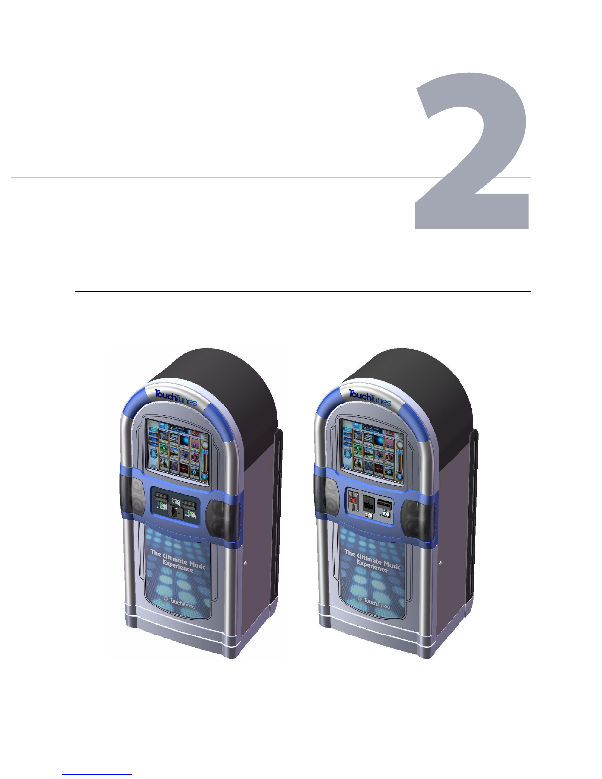
U.S. Model: Dual bill acceptor
and card reader.
Canadian Model: Single bill acceptor,
coin acceptor, and card reader.
*
Models may differ slightly from those illustrated in this document.
This chapter provides an overview of the Allegro MX-1 jukebox and explains
how to access its major components.
Introducing Allegro MX-1
The Allegro MX-1 is TouchTunes’ new re-designed and streamlined floor-model jukebox*.
Allegro MX-1 (U.S. and Canadian Models)
5

Allegro MX-1: An Overview
Evolving from the design of TouchTunes’ hugely successful Allegro, the advanced and innovative
Allegro MX-1 boasts the following among its attractive design features and benefits:
• A smaller footprint, allowing for installation in locations of a wide
variety of shapes and sizes.
• Ease of transport, installation, and maneuverability.
• Simple cabling with intuitiv
• Improved heat dissipation and cooling capability
onnectivity.
e c
, thanks to a power supply and heat sink
system that is external to the computer.
• Fanless cooling system, eliminating the need for maintenance such as filter replacement and
cleaning
Availability of fast diagnostics—on site and remotely.
•
.
• Quick access to and replacement of any component.
• Newer hard disk technology (SATA
• Support for simultaneous external HD video fo
vs. IDE).
r expansion into Gaming and Advertising
capabilities.
• Improved durability and reliability.
• The most robust and reliable paym
ent m
eans to date.
• Improved, longer-range remote control receiver.
• Integrated amplification, providing sound for 3 independent audio zones.
• Unparalleled volume and audio clarity.
Components and Features
This section provides details of the Allegro MX-1’s key components and features.
Sound
• Built-in Digital Signal Processing (DSP) microprocessor for superior audio quality, equalization,
and noise reduction.
• Class D switching amplifiers.
• Built-in three channel (2 X 150 W + 1 X 300 W) to produce a minimum of 104 dB SPL when using
the internal aco
• Second internal amplifier, four full range channels (4 X 150W), for zones two and three (double
stereo amplifier).
• P
rotected against over-voltage, over-current, overload and output short circuits.
• Less than 0.05% THD +N at 75 W into 4 ohms.
• Built-in bass box and satellite speakers (non removable).
• Four external satellite speakers.
• All speakers equipped with fast-on terminal c
replacement.
See “Amplifier Overview” on page 8 for further details.
stics of the Allegro MX-1.
u
nnectors for easy removal and driver
o
6

Touch-screen Monitor
• 19 inches (4:3 aspect ratio).
• Newly designed six-degree tilted monitor for optimized viewing angle.
• Surface Acoustic Wave (SAW) technology.
Components and Features
• LCD panel with a minimum viewing angle of 150 deg
r
ees, horizontal and vertical.
• Native resolution of 1024 X 768 (standard TFT Resolution).
• 3 millimeters touch glass thickness.
• Minimum 500 to 1 contrast ratio.
Cabinet
• Wooden construction, 18 millimeters MDF.
• Small footprint, with the mechanical stability
• Fanless unit using natural convection air flow.
• Internal lighting and door-open log.
• Service tray providing easy access to components for maintenance.
• Optical sensor-controlled service light, providing illumination of
service tray for increased visibility and ease of service.
• Mesh protection at bottom to prevent the entry of insects.
• Cabinet base equipped with four rotating casters and f
• Satellite speakers, being part of the cabinet structure.
• Rear of cabinet equipped with handles for maneuv
bed.
required by UL Safety Standards.
our adjustable levelers.
ability enable sliding the unit on a pickup
er
the cabinet’s interior and
• All screws fastened from the interior, preventing external dismantle.
• Plastic-reinforced base.
Door
• Multipart injection plastic door (thermoplastic).
• Metallic speaker grills.
• Payment means and poster frame sections open together fo
• Door parts field-replaceable.
Payment Means
Note: Installed payment means components may vary by region.
• ICT bill acceptors (1000-bill stacker); capable of reading coupons.
• Coin acceptor:
• For US: none.
r service access.
7

Allegro MX-1: An Overview
• For Canada: $2, $1 and $0.25.
• Credit Card reader (US and Canadian models only).
Note: Before using credit card readers on your jukebox, you must enter a special contractual
agreement with TouchTunes. For information, contact TouchTunes.
See “Contacting TouchTunes” on page 4.
Note: The card reader is not capable of reading Smart Cards.
Remote Controls
• One wireless RF remote.
• One wired remote.
Lightshow
• Compatible with TouchTunes’ existing system (Color Kinetics/Philips).
• Six channels daisy chained, four channels for the two lens
es of the bottom part of the door and
two channels for the two lenses on the top.
• Polycarbonate (Translucent PC) lightshow lens.
• External standard DMX interface.
Poster Frame
• Easy access, requiring no tools for poster replacement, accommodating the same overall size
poster as the Allegro.
• Backlit with white LED strips.
System
• JCB architecture with DSP technology.
• Gen 3 software compatible.
• 3 stereo out, line-in, mic-in.
•
power from 100 to 120 VA
• 0 - 40 deg. C ambient temperature.
• Designed to withstand normal transportation vibration and support frequent moving, (in and
out of location, pickup transport).
C 50-60 Hz, 10.0 amps max
Amplifier Overview
The Allegro MX-1 jukebox is equipped with two versions of the TouchTunes class D digital audio
amplifier:
8

Amplifier Overview
• A 3-channel amplifier: This amplifier is incorporated into the Allegro MX-1’s internal sound
system, providing sound for audio zone 1. The 3-channel amplifier supports daisy-chaining of
audio components.
• A 4-channel, 2-zone amplifier: This amplifier pro
vides sound for audio zones 2 and 3, and does
not support daisy-chaining of equipment.
The 3 and 4-channel amplifiers incorporate the following features:
Feature/Specification
Uncompromising sound quality. 99
Dynamic range of 102dB. 99
Over-current protection. 99
Mute input. 99
Turn-on and turn-off pop suppression. 99
Over-temperature protection. 99
High speed switching power supply. 99
Less heat, smaller footprint. 99
Total harmonic distortion ≤ 0.05% (1W). 99
Signal-to-noise ratio ≥ 105dB (A-weighted). 99
Two balanced inputs. 9
Four-channel
amplifier
Three-channel
amplifier
One input supporting daisy-chaining. 9
Two stereo outputs (full-range). 9
One stereo output (midrange and high
frequencies)
One bass output (low frequency).
AC line voltage and frequency:
90 to 130 V AC/ 50 - 60 Hz
4-ohm (minimum) load per channel (150W). 99
8-ohm per channel (75W). 99
Benefits of these amplifie
nclude:
rs i
99
9
• Requirement of only N-Channel MOSFET output transistors.
• Dramatic improvement in efficienc
versus Class AB amplifiers.
y
• Signal fidelity equal to high-quality linear amplifiers.
• High dynamic range compatible with digital media.
9
Allegro MX-1: An Overview
Bottom Panel
h
i
j
k
l
m
n
a
b
c
d
e
f
g
a
Top Panel
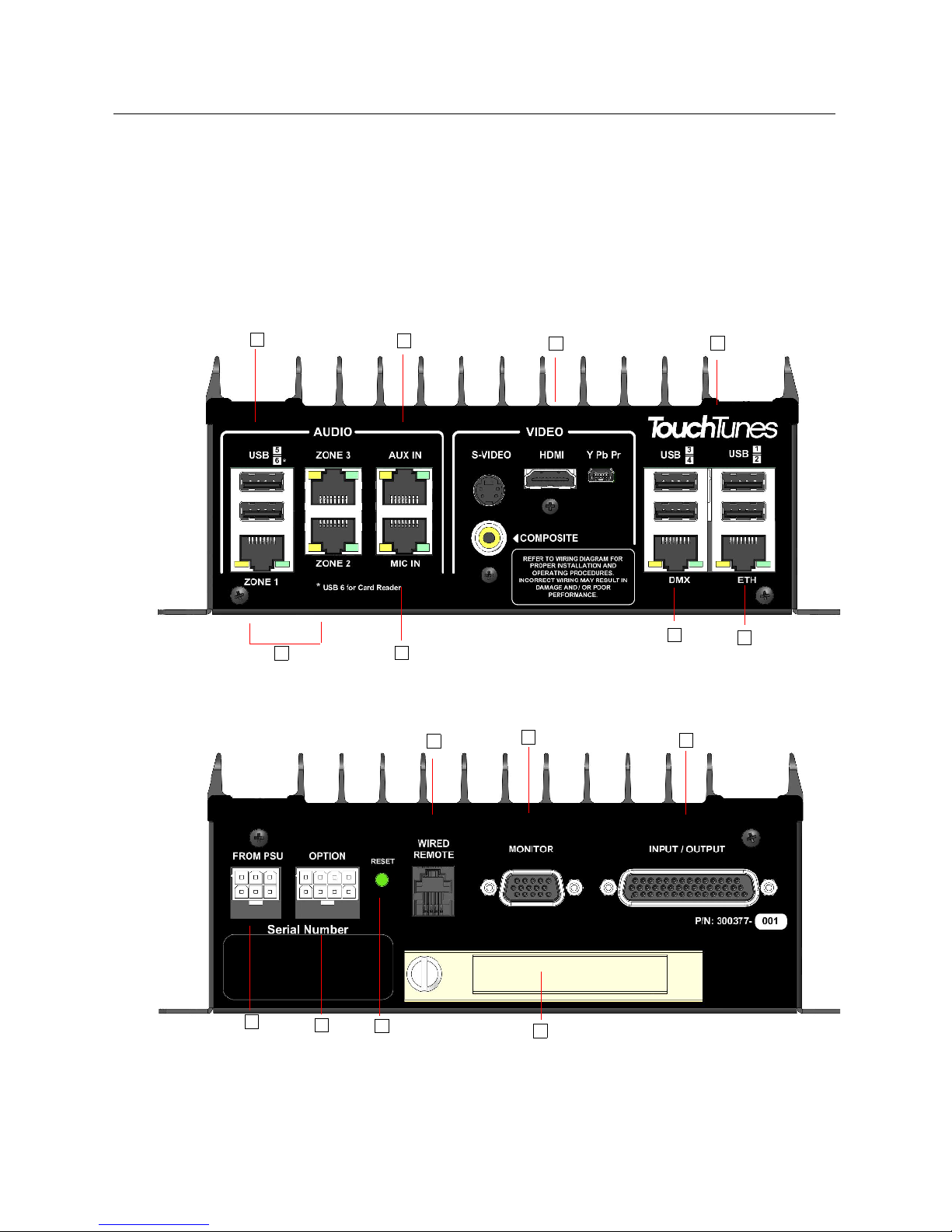
JCB Computer Overview
The central computer in your Allegro MX-1 jukebox, called the JCB, is a specially designed
computer mounted inside the Allegro MX-1 that runs the jukebox. Like a regular laptop or
desktop computer, the JCB contains a hard drive and USB connectors for attaching peripherals.
To conserve space, the JCB has connections on both its top and bottom panels, as well as
controls and indicators on its front panel.
Refer to the following figures to identify all components and connections on the JCB for your
jukebox.
Layout of JCB: Top Panel—a) USB ports for peripheral devices; b) Audio zone outputs; c) Microphone input; d) Auxiliary
audio input; e) External video outputs; f ) External light show connector; g) Ethernet port
Layout of JCB: Bottom Panel—h) Power supply connector; i) Power for external equipment; j) System reset (reboot); k) Wired
remote connector; l) Touchscreen connector; m) Hard disk drive; n) I/O connector
10
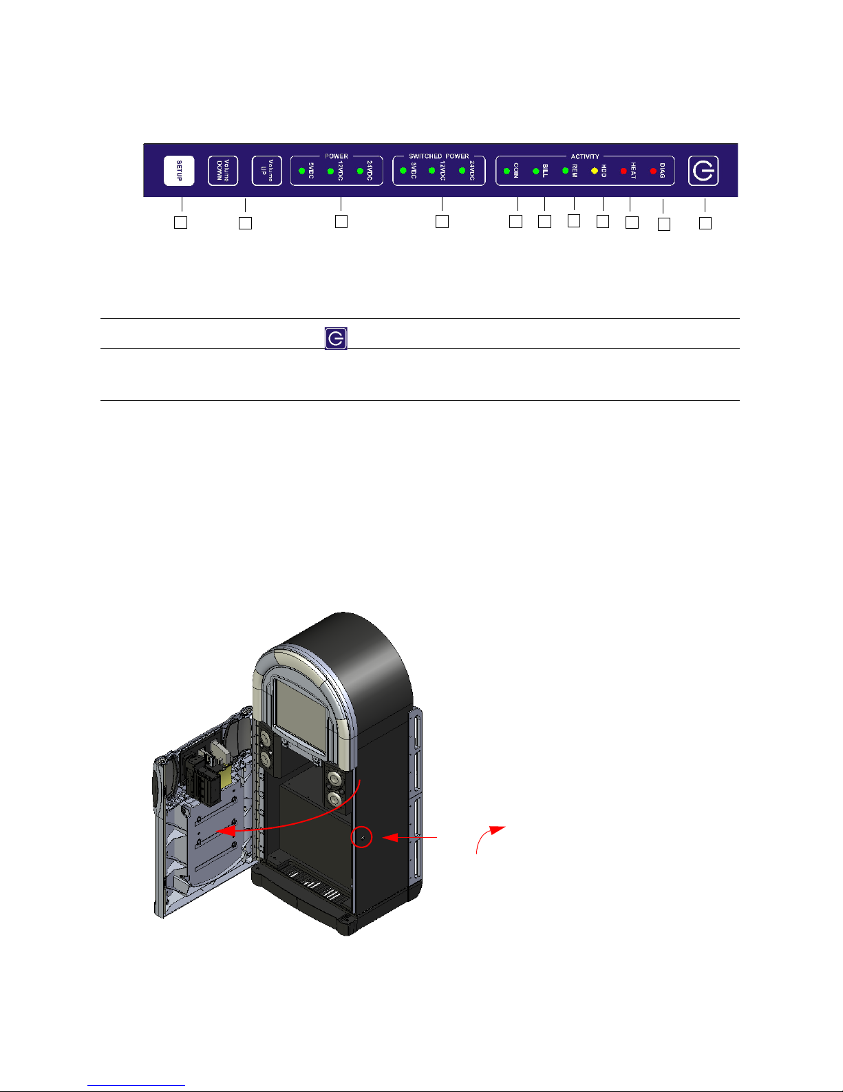
Layout of JCB: Front Panel Controls—o) Setup button; p) Volume control buttons; q) Power status indicators; r) Switching
Unlock
Front Panel
o
p
q r s t
u
v
w
x
y
power status indicators; s) Coin acceptor activity indicator; t) Bill acceptor activity indicator; u) Wired remote activity
indicator; v) Hard drive activity indicator; w) Overheat indicator; x) Diagnostic LED; y) Power button for monitor and
acceptors
Note: The power button (y) does not turn off the jukebox computer.
Accessing Components
This section explains how to gain access to Allegro MX-1’s main components for the initial setup
and subsequent servicing.
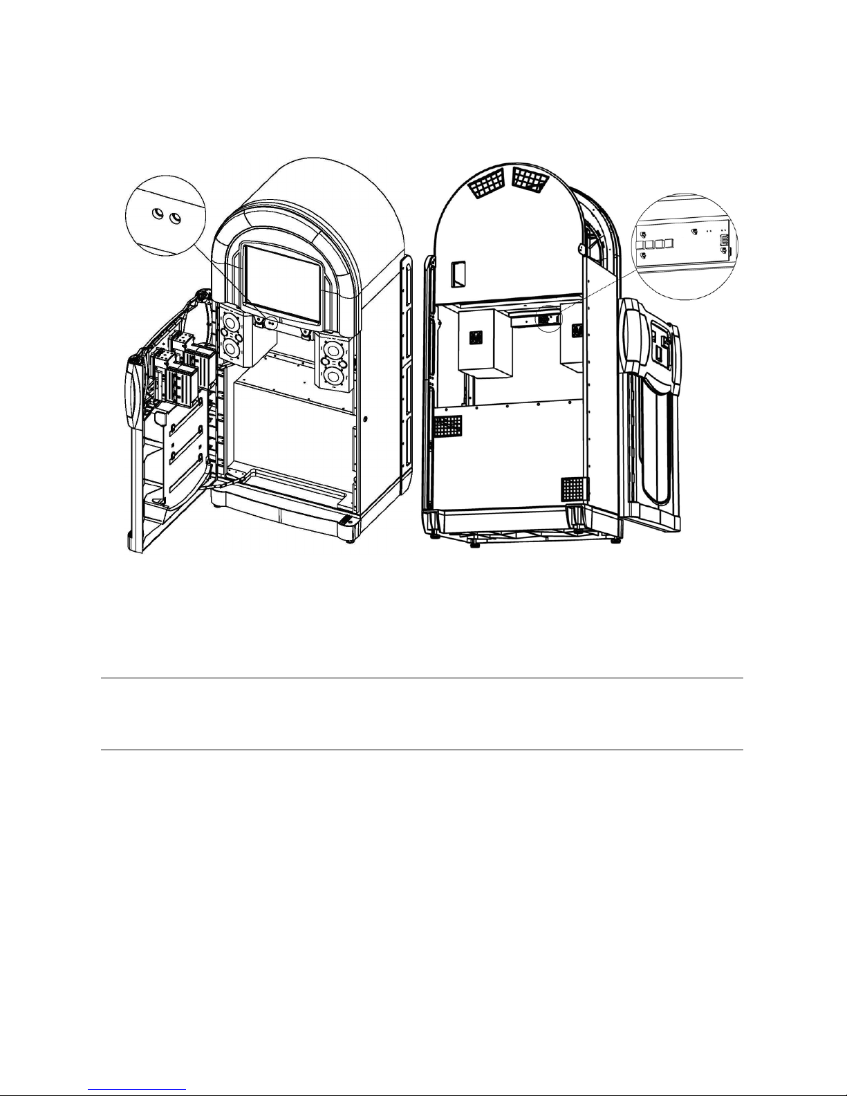
Accessing Components
Opening the Main Enclosure
To open the main enclosure:
1. Locate the key for the Allegro MX-1.
2. Unlock the Allegro MX-1 from the right side of the jukebox and then slowly swing open the
Allegr
o MX-1 case.
Opening the Allegro MX-1
11
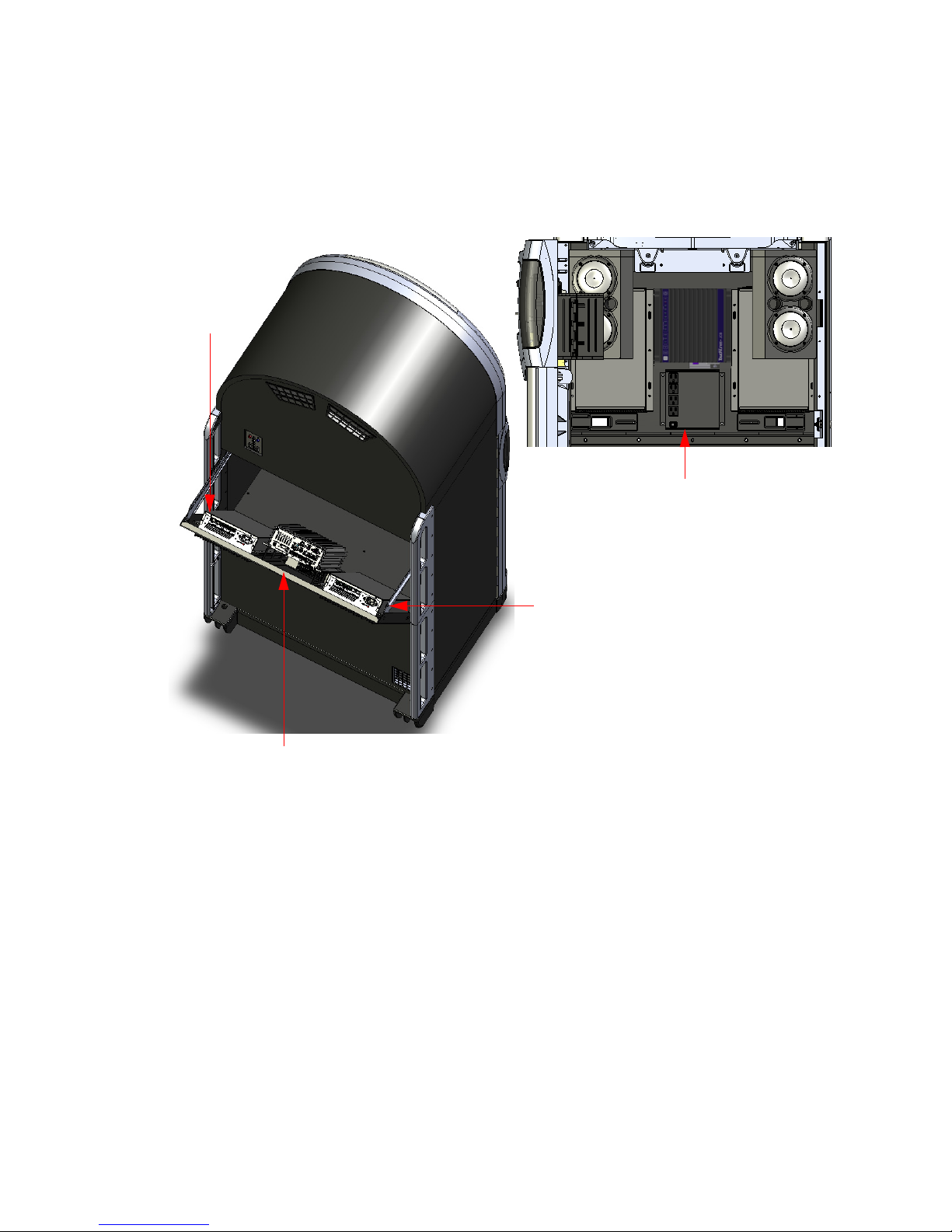
Allegro MX-1: An Overview
Amplifier for
internal speakers
Computer
Second amplifier
View from cabinet interior (showing power supply)
for zones 2 and 3
(zone 1)
When the jukebox is powered up, and the door is opened, the optically controlled service light
illuminates the interior of the cabinet. See “Service Light” on page 16 for details.
Accessing the Service Tray
The service tray, located in the rear of the enclosure, provides access to the computer,
amplifier(s) and power supply.
Service tray
The service tray is hinged at the bottom and travels outward on two slide rails fastened to the
upper part of the tray. To prevent access by unauthorized personnel, the service tray must be
unlocked from within the cabinet’s interior.
Opening the Service Tray
To open the service tray:
1. Unlock and open the front door of the Allegro MX-1, as described in “Opening the Main
Enclosure” on page 11.
12
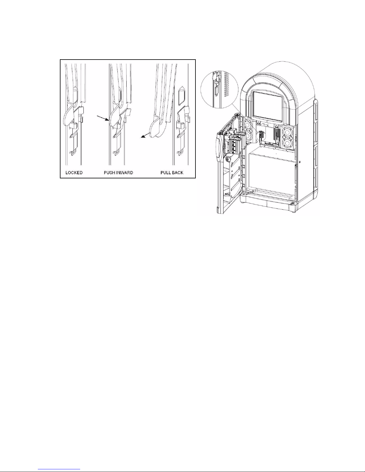
Accessing Components
2. Locate the two locking slide rails on either side of the service tray at the rear of the cabinet’s
interior.
Opening the service tray
3. Disengage the rails from the locking tabs by pressing them inward toward the center of the
enclosure, and then pulling back as far as they can travel.
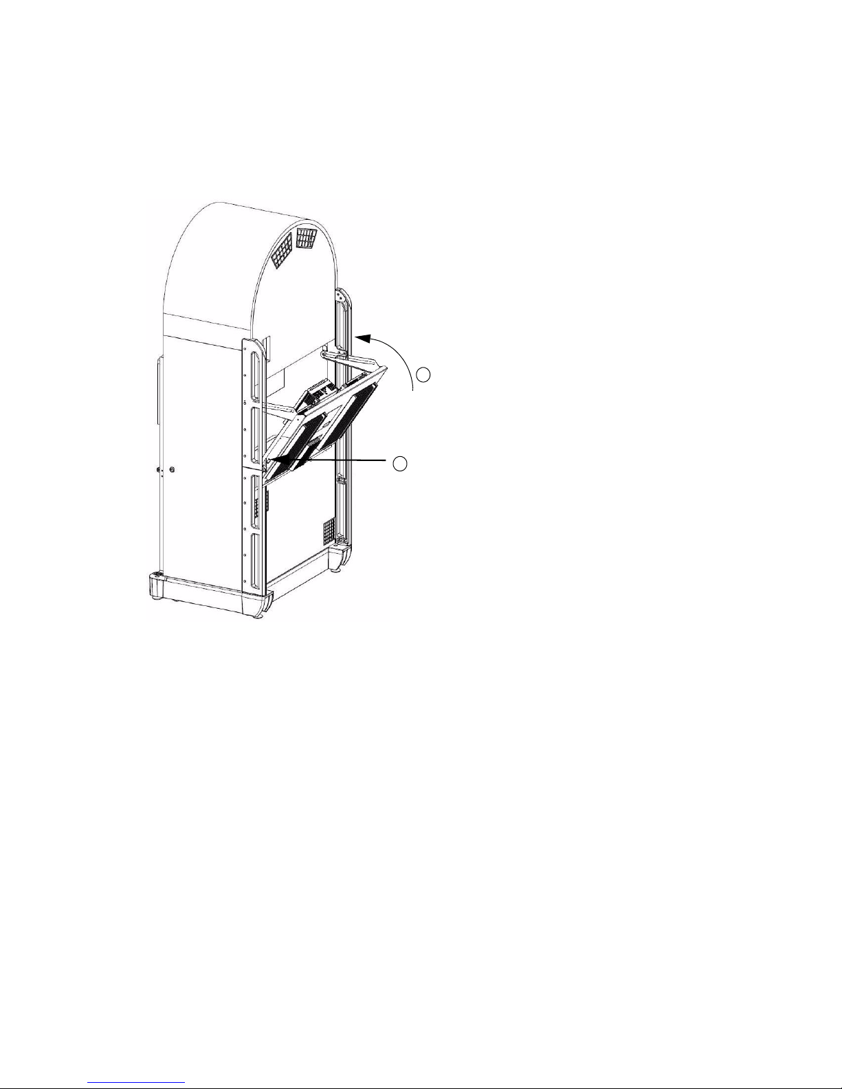
4. Gently push the service tray outward, letting it slide along the rails.
Components in the service tray are also accessible from the interior of the cabinet, allowing
con
venient access
to the bottom panel of the JCB computer.
13
Allegro MX-1: An Overview
Push tray
inward
1
Snap rails firmly
over locking tabs.
2
Closing/Locking the Service Tray
In order to prevent unauthorized access to the Allegro MX-1’s components, it is important to
close and lock the service tray when you have completed servicing.
To close and lock the service tray:
1. Push the service tray inward until it is flush with the rear wall of the cabinet.
14
Closing and Locking the Service Tray
2. From the interior of the cabinet, ensure that the service tray is locked in place (i.e., the rails are
firmly seated over the locking tabs in the metal frame of the service tray).
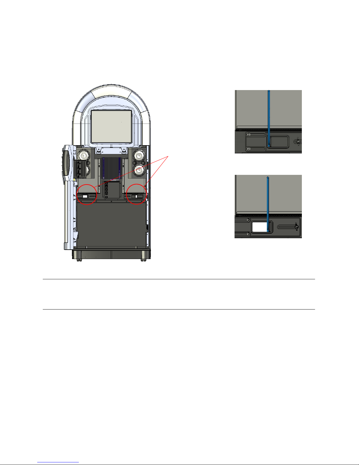
Accessing Components
Closed position; wing nut
Cable access/strain relief
ports
tightened to secure cable.
Open position; wing nut
loosened to allow access.
Routing Cables to the Service Tray Components
The Allegro MX-1 is designed with two cable access ports on the service tray that allow you to
route outside cables (such as for telecommunications and speakers for zones 2 and 3) to internal
jukebox components. The cable access ports also act as wire-strain relief devices, providing slack
for cables inside the jukebox and covering the opening to the interior to keep dust out.
Cable access ports on service tray
Note: Only route cables in to and out of the jukebox through the provided cable channel
opening. Do not route cables through any other openings in the jukebox, such as air vents.
Otherwise, the jukebox may overheat and shut itself down.
To prepare for cable routing in the jukebox:
1. Identify the cable access ports on the Allegro MX-1’s service tray.
2. Loosen the wing nuts for wire-strain relief so you can move the sliding tab.
3. Adjust the sliding tab so you can bring cables into the jukebox through the cable channel
op
ening
.
Once the cable channel is open and the wire-strain relief sliders are loose, you are ready to make
connections to the jukebox.
15
Allegro MX-1: An Overview
Optical
sensors
LEDs
Service Light
The Allegro MX-1 is equipped with a service light module that plugs into the main wiring harness
and illuminates the interior of the cabinet, facilitating servicing in low-light situations.
Service Light Module, Front and Rear Views
When the door of the Allegro MX-1 is opened, optical sensors mounted in a circuit board in the
interior of the cabinet activate a panel of high-intensity LEDs that are pointed toward the service
tray, providing illumination to the interior.
When the door is closed, the service lighting extinguishes.
Note: A reflective strip for the optical sensors is mounted on the interior of the door (adjacent to
the payment acceptors). To ensure proper continued operation of the service light component,
TouchTunes recommends that you keep this reflective surface clean when making a service call.
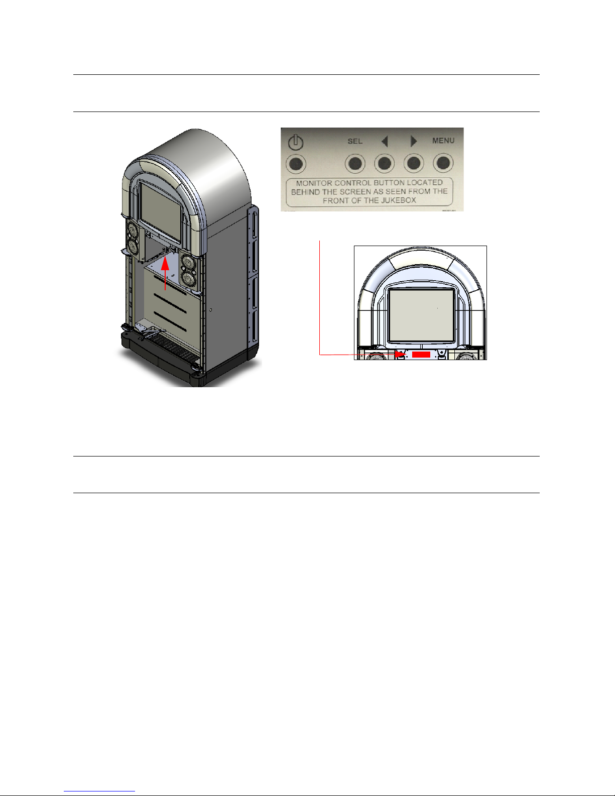
Accessing the Rear of Monitor
Should minor adjustments be required, you can access the On-Screen Display (OSD) controls on
the rear of the monitor by reaching up from within the enclosure.
16
Accessing Components
Note: The controls on your model may differ.
Sample monitor control legend.
Note: Refer to the legend provided on the self-adhesive label affixed to the cabinet below the
monitor bezel to guide you when performing monitor adjustments.
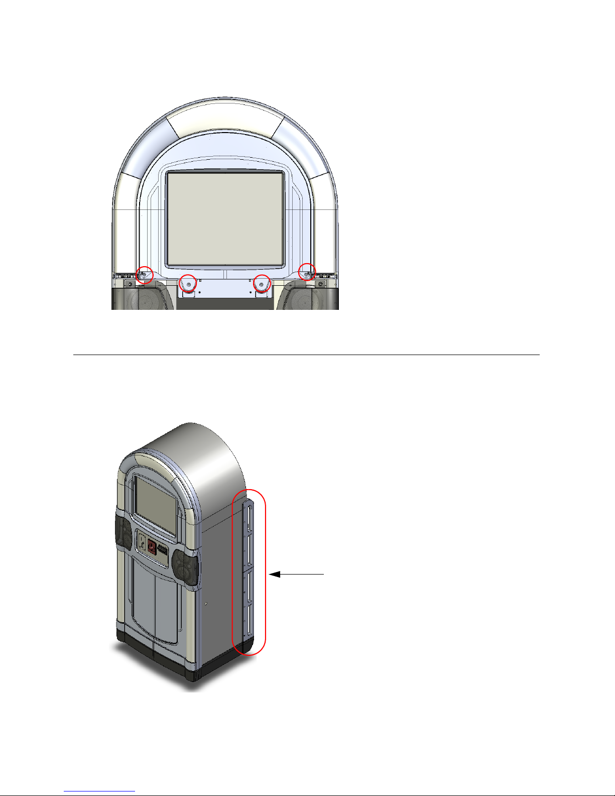
Accessing the monitor
To remove the monitor entirely for servicing or replacement:
1. Unscrew and remove the four screws that fasten th
e monitor assembly in place.
Note: The monitor is seated in the cabinet such that it cannot fall forward when the screws are
removed.
17
Allegro MX-1: An Overview
Use transport rails
when maneuvering jukebox.
2. Grasp the monitor assembly by its bottom center, lift upward and then outward.
Location of monitor mounting screws
Transporting Allegro MX-1
The Allegro MX-1 is equipped with transport handles built in to the rear of the enclosure. Use
these handles when transporting the Allegro MX-1 and when maneuvering it into position at the
location.
Transport rails
18
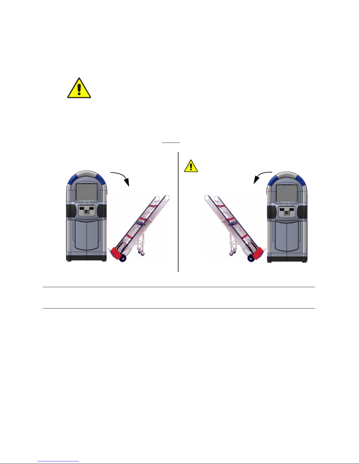
Transporting Allegro MX-1
9
Correct
Ensure that door is
Correct
9
locked when moving
the jukebox this way.
You can lay the Allegro MX-1 on its back when transporting it, and use the transport handles as
rails to slide it in or out of a pickup truck bed or van. Resting it on its handles also provides
protection for unpackaged transportation of the jukebox, preventing scratching of the cabinet.
CAUTION: Exercise caution when tipping the Allegro MX-1 onto an appliance dolly
or hand cart; it can fall onto you and cause serious injury.
Always have adequate assistance when moving the Allegro MX-1, particularly
when negotiating stairs—it is very heavy (269 lbs/122 kg).
Follow all appropriate safety precautions.
The transport handles also perform a secondary function, providing the necessary space
between the wall and the cabinet for optimal performance of the bass box.
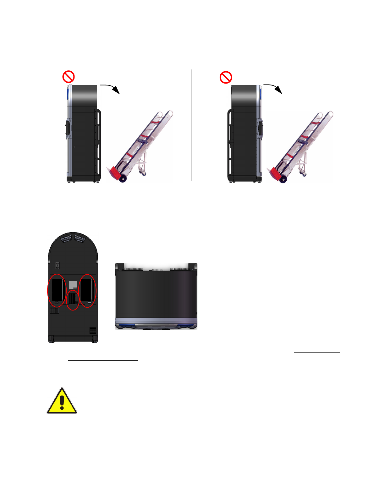
When transporting the Allegro MX-1, always
or right-hand side.
tip the Allegro MX-1 onto the hand cart from its left
Using a Hand Cart
Note: If tilting the jukebox from its left-hand side onto a cart, ensure that the door is closed
securely and locked, otherwise it may flip open, causing damage or personal injury.
Why transport the jukebox this way?
• By tilting the jukebox frontwards onto a cart, you risk scratching or cracking the moulded
plastic of th
e cabinet, the touch screen, and the light show lenses.
19
Allegro MX-1: An Overview
Incorrect
Incorrect
Risk of damage to
amplifiers and/or power
Risk of cosmetic
damage to front.
supply.
Overhead view
• By tilting the jukebox backwards onto a cart, you risk placing the weight of the jukebox on the
heat sinks of the 2 amplifiers, which may cause them to dislodge from their mountings on the
service tray and become vulnerable to subsequent damage
Do Not Rest Jukebox on its Front or Back
Never Place a Load on the Power Supply and Amplifier Heat Sinks.
To provide optimum cooling capability, the heat sinks of the Allegro MX-1’s power supply and
two digital audio amplifiers are on the exterior of the cabinet (mounted on the service tray at the
rear).
.
When transporting the Allegro on the bed of a pickup truck or the floor of a van, always slide the
unit on its transport rails into the vehicle, and let the weight of the cabinet rest solely on the
transport rails. Do not introduce any obstacles between the vehicle’s floor and the cabinet that
may cause the cabinet to rest on the heat sinks of the amplifiers or power supply.
When transporting the Allegro MX-1:
NEVER LAY THE CABINET ON ITS BACK AND TRANSPORT IT WITH A HAND CART
BENEATH IT!
1. Turn off the system power switches on the Allegro MX-1’s computer and internal power
supply.
20
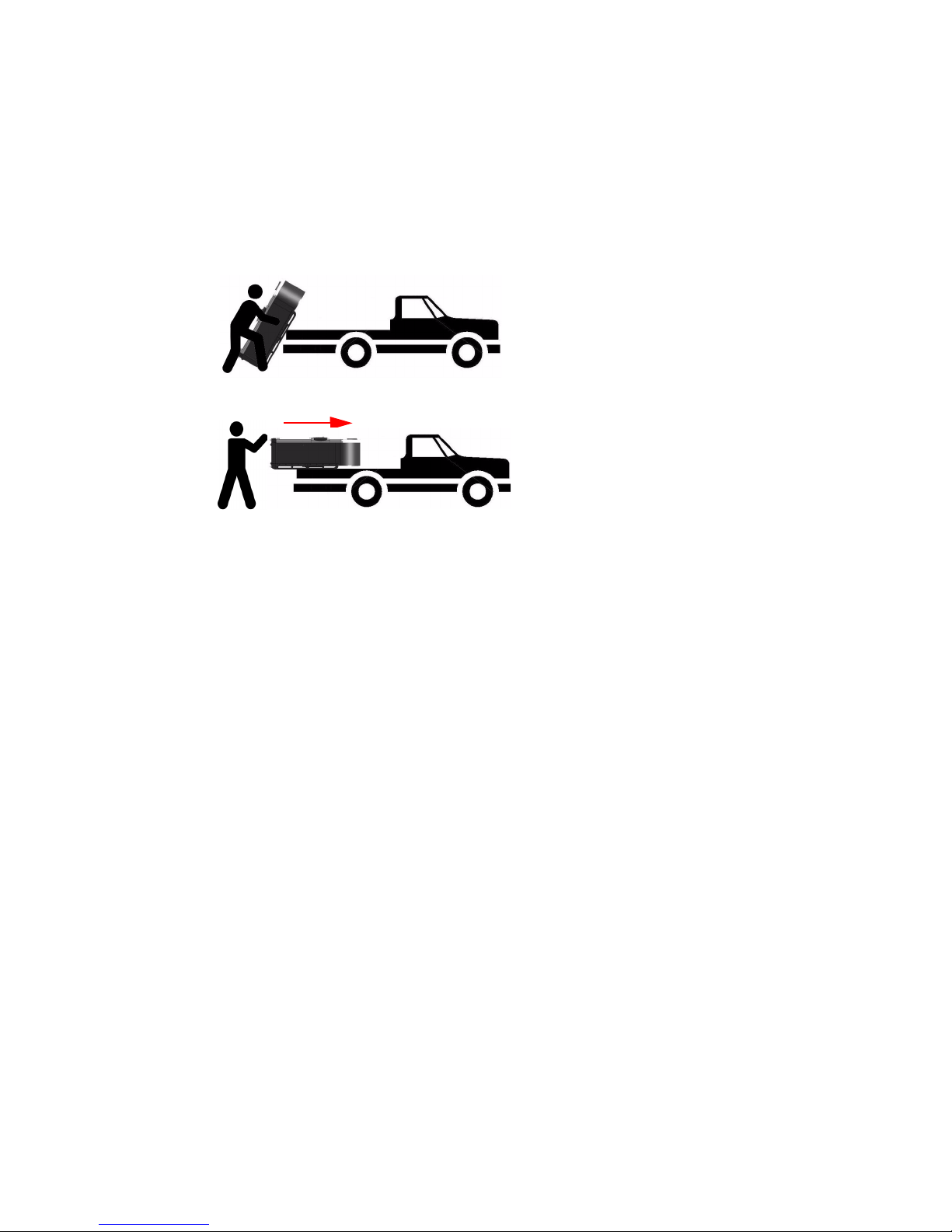
2. Disconnect the power and network cables.
Slide jukebox on
its transport rails.
Lift onto
vehicle.
3. Close and lock the jukebox.
4. To the extent possible, protect the jukebox for transportation.
Transporting Allegro MX-1
5. Maneuver the jukebox close to the rear of the
veh
icle, remove it from the hand cart, and
position it with its back facing the vehicle.
6. With an assistant, tilt the jukebox backward and lift it onto the vehicle.
Transporting Allegro MX-1 on a Truck Bed
7. Slide the jukebox on its transport rails onto the vehicle.
8. Transport the jukebox to the new location.
21

Allegro MX-1: An Overview
22

Pre-Installation
This chapter explains how to prepare to install a TouchTunes Allegro MX-1
jukebox for a location, including setting up communications connections and
unpacking the jukebox.
Unpacking and Checking Jukebox Components
A TouchTunes jukebox is delivered in several boxes, including boxes for the jukebox hardware
components and a parts kit. The following table shows the dimensions and weight of the
Allegro MX-1 jukebox:
Height Width Depth Weight
Crated
Uncrated
71 1/4” (181 cm.) 30 1/2” (77.5 cm.) 24 3/4” (63 cm.) 335 lbs. (152 kg)
66 3/4” (169.5 cm.) 29 3/4” (75.6 cm.) 24” (61 cm.) 269 lbs. (122 kg)
Before you install the jukebox, you must ensure that you have received all jukebox hardware
components and that both hardware components and the items in parts kit are in good
condition.
To check that you have all jukebox components:
1. Verify that you have received the following hardware components for the Allegro MX-1
jukebox:
Component
Quantity
1 Allegro MX-1 Digital Jukebox (p/n 700222-001)
1 3-prong power cord
1 Parts kit
Component
Description
23
Pre-Installation
2. Open the Parts kit and then verify that it contains all of the following components:
Component
Quantity
1 Single frequency remote control kit 600069-001-001
4 External satellite speakers 700185-001
2 Keys (attached to rear of jukebox) 400157-001
1 Microphone box 700166-001
1 DI box (line input) 700167-00
1 Eurostyle terminal con
1 5-mm. hex-head bit for adjusting levellers N/A
Component
Description
nector (4-position) 100000
3. Check the condition of all hardware components and parts k
good condition.
Caution:
parts kit is damaged. Contact your distributor or TouchTunes to report the damage
immediately and request replacement parts.
Do not attempt installation if any jukebox hardware component or item in the
Setting Up a Broadband Connection
Every night, a TouchTunes jukebox contacts the main TouchTunes server over the Internet to do
the following tasks:
• Download any new songs chosen by location owner or operator through the TouchTunes
Dashboard.
TouchTunes
Part Number
-001
it items to ensure they are in
• Do
wnload any new updates to the jukebox system software.
• Download the TouchTunes music catalog.
• Report the number of plays per song for music royalty calculations.
• Report daily income for the jukebox.
The connection to the Internet is provided through an Internet Service Provider (ISP). ISP
rmally offer two different types of Internet connections: dial-up and broadband. TouchTunes
no
s
recommends using a broadband connection, as the connection type you chose has an impact
on the infrastructure needed for the jukebox as well as the speed of jukebox communications.
A jukebox using a broadband connection uses a special, high-speed network to connect to the
Internet and to the TouchTunes server. Broadband connections allow much faster
communications speeds than dial-up connections, but require a broadband modem and/or
router (computer networking device) to connect the jukebox to the high-speed network.
Use the following guidelines to help you choose and set up the Internet connection type for the
jukebox:
• TouchTunes recommends using broadband Internet conne
ctions for jukeboxes whenever
possible. The broadband connection:
• Permits the jukebox to download new songs much more quickly than over a dial-up
conne
ction.
• Allows you to change jukebox settings via
ouchTunes Dashboard and apply them
the T
immediately to the jukebox.
24
 Loading...