

TouchTronics 1210-R, 1211-R, 1212-R, 1213-R, 1221-R Service Manual
...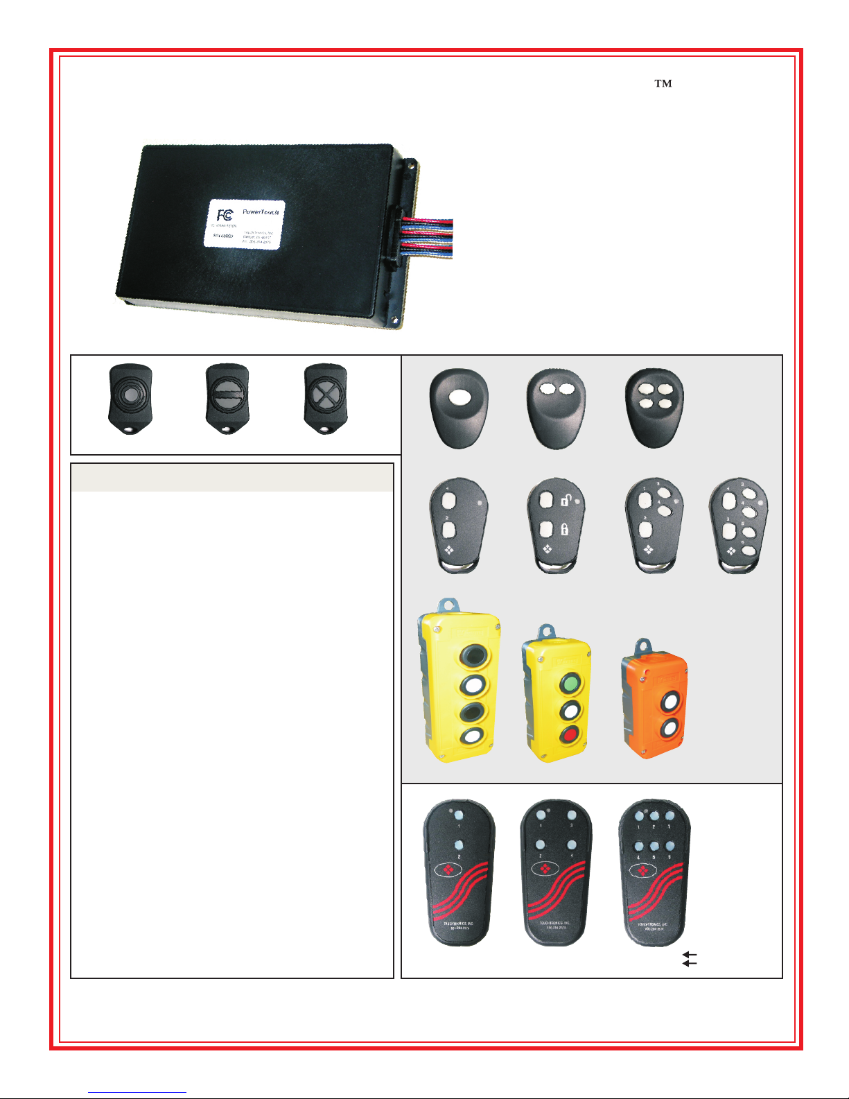
POWERTouch 1200
Radio Frequency (RF)
Remote Control System
1230-R
P1000-TM1 P1000-TM2 P1000-TM4
System Specifications
Model # P12xx-R Sealed
(see pg 2 for model number chart)
Range - 300 Feet Typical
- Up to 600 Feet
Output - 4 Relays
Optional - 7 Relays
Input - 2 (+12v) A1 & A2
Optional - 6 (+12v or Ground) B1 - B6
.
Frequency - 433MHz
Harness w/
Sealing Gasket
Service Manual
Sealed Receiver:
Moisture & Dust
P1000-TK1 P1000-TK2 P1000-TK4
P1000-TF2 P1000-TF2-LK P1000-TF4
TK, TF & TR Series
Sealed
Transmitters
P1000-TF6
Codes - Rolling Codes
- Secure Encryption
Voltage - 12VDC
- 24VDC
Current - 5 Amps Max per Output
- 10 Amp Input - Standard
- 30 Amp Input - Optional
Antenna - Fixed - Standard (shown)
Optional - TNC Whip
- Flex Whip / Roof Mount
- Flex Whip / Glass Mount
Harness - 9” Standard, 14 pin
Battery - All transmitter styles (except TR style)
- Coin Style, Lithium, CR2032
- 100,000 1-second pulses
- 10 year shelf life
- TR Style - 2 x “AA” Batteries
T T Iouch ronics, nc.
P1000-TR4 P1000-TR3 P1000-TR2
P1000-TX2 P1000-TX4 P1000-TX6
P1000-TX2S P1000-TX4S P1000-TX6S
57315 Nagy Drive
Elkhart, IN 46517
www.touchtronics.com
touchtronics@touchtronics.com
No ON/OFF Switch
With ON/OFF Switch
Ph: 800-294-2570
Fx: 574-293-1611
Manual NST11424-2
2010-04-05 Rev F
System Operation
Each time a button is pressed on the transmitter, the corresponding output will turn On. For example, if button #1
is pressed, output #1 will turn On as long as the button is held.
If an input signal is sent to inputs A1 or A2, or any inputs B1 - B6, the corresponding output will turn On as long as
the signal is present. (A1 or B1 = Output #1 is ON. A2 or B2 = Output #2 is ON)
Each output is factory set as momentary. To change output from momentary to latching (push on / push off) see
DIP Switch options detail on page 3.
Installation
Receiver Installation
Determine mounting location of receiver and
antenna - typically under the dash or behind a
wall.
Antenna Installation
1. The antenna must be installed in an open,
non-metal area in order to receive RF (radio
frequency) transmissions.
2. Antenna range will be reduced if located:
A) within 6 feet of a large motor
B) near large bundles of wires
C) near other RF devices
D) touching any metal
To Increase Antenna Range
A) Install exterior mount NMO Antenna
See page 4 for accessory antenna options
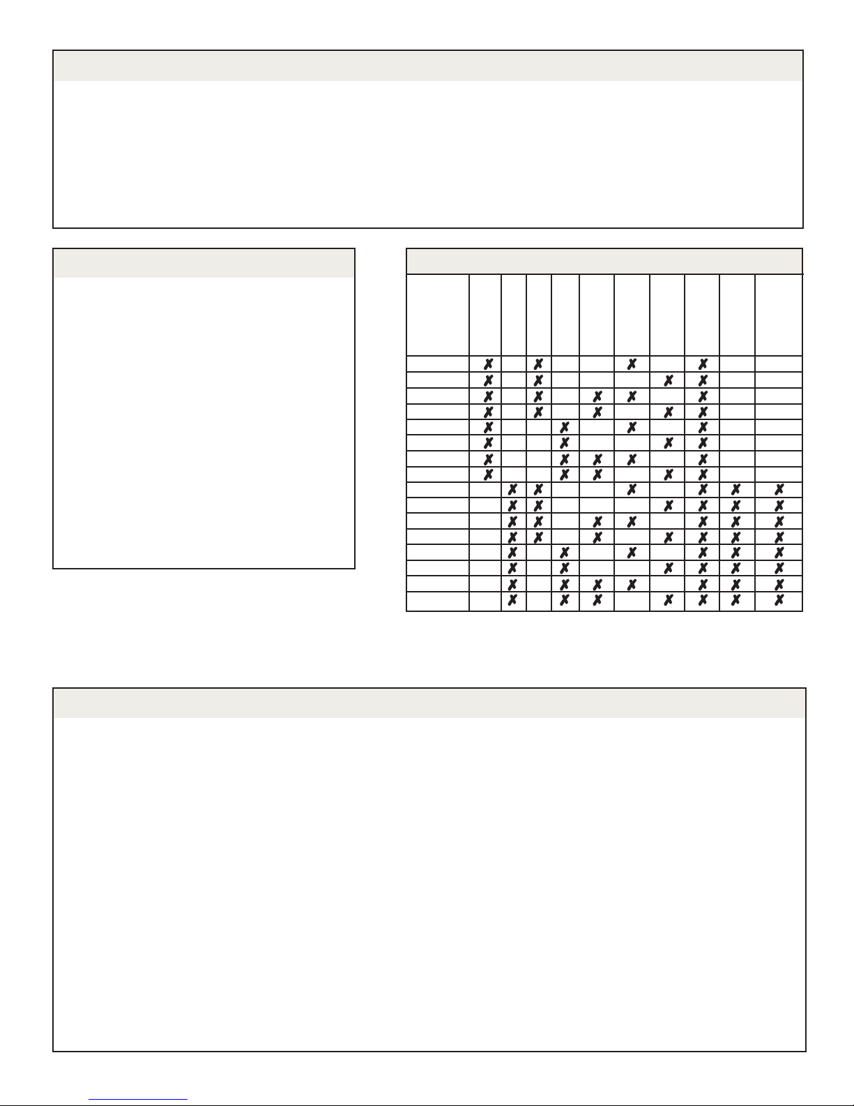
Receiver
Model
1210-R
1211-R
1212-R
1213-R
1220-R
1221-R
1222-R
1223-R
1230-R
1231-R
1232-R
1233-R
1240-R
1241-R
1242-R
1243-R
Sealed Receiver Model Number Chart
4 - Relays
7 - Relays
12VDC
24VDC
30A
Connector
Fixed
Antenna
TNC
Antenna
A1 & A2
Switch Inputs
B1 - B6
Switch Inputs
Input
Status
LEDs
ENROLLING NEW TRANSMITTERS - Self-Learning Receiver
1. Remove and reconnect power to unit. This will place unit into LEARN mode for 5-seconds.
2. Press any button on transmitter once. Wait 5-seconds and confirm the transmitter has been enrolled by
pressing any button and verifying the correct output turned ON.
OR
1. Remove cover from receiver enclosure.
2. Locate LEARN switch (*small, push-button style switch located in the corner of the printed circuit board).
3. Press and release the LEARN switch
The Red LEARN LED next to the switch will flash
4. Press any button on NEW transmitter.
6. Red LEARN LED double blinks to confirm enrollment.
7. Press any button on the new transmitter to confirm that the new transmitter code has been enrolled.
8. Replace receiver enclosure cover.
Erasing Enrolled Codes
1. Press and hold the LEARN switch (*see # 2 above) for 10-seconds.
2. Red status LED will flash while holding LEARN switch
3. Release LEARN switch when Red LED double flashes to confirm ALL transmitter codes are erased.
Code Enrollment
Page -2-
 Loading...