

User Guide
TouchLink
™
TLP Pro 520M and TLC Pro 521M
TouchLink Touchpanel Control System
68-2153-01 Rev. B
06 16
Safety Instructions
Safety Instructions • English
WARNING: This symbol, D, when used on the product, is intended
to alert the user of the presence of uninsulated dangerous voltage
within the product’s enclosure that may present a risk of electric shock.
ATTENTION: This symbol, I, when used on the product, is
intended to alert the user of important operating and maintenance
(servicing) instructions in the literature provided with the equipment.
For information on safety guidelines, regulatory compliances, EMI/EMF
compatibility, accessibility, and related topics, see the Extron Safety and
Regulatory Compliance Guide, part number 68-290-01, on the Extron
website, www.extron.com.
Sicherheitsanweisungen • Deutsch
WARNUNG: Dieses Symbol D auf dem Produkt soll den Benutzer
darauf aufmerksam machen, dass im Inneren des Gehäuses dieses
Produktes gefährliche Spannungen herrschen, die nicht isoliert sind
und die einen elektrischen Schlag verursachen können.
VORSICHT: Dieses Symbol I auf dem Produkt soll dem Benutzer
in der im Lieferumfang enthaltenen Dokumentation besonders wichtige
Hinweise zur Bedienung und Wartung (Instandhaltung) geben.
Weitere Informationen über die Sicherheitsrichtlinien, Produkthandhabung,
EMI/EMF-Kompatibilität, Zugänglichkeit und verwandte Themen finden Sie
in den Extron-Richtlinien für Sicherheit und Handhabung (Artikelnummer
68-290-01) auf der Extron-Website, www.extron.com.
Instrucciones de seguridad • Español
ADVERTENCIA: Este símbolo, D, cuando se utiliza en el producto,
avisa al usuario de la presencia de voltaje peligroso sin aislar dentro del
producto, lo que puede representar un riesgo de descarga eléctrica.
ATENCIÓN: Este símbolo, I, cuando se utiliza en el producto,
avisa al usuario de la presencia de importantes instrucciones de uso y
mantenimiento recogidas en la documentación proporcionada con el
equipo.
Para obtener información sobre directrices de seguridad, cumplimiento
de normativas, compatibilidad electromagnética, accesibilidad y temas
relacionados, consulte la Guía de cumplimiento de normativas y seguridad
de Extron, referencia 68-290-01, en el sitio Web de Extron,
www.extron.com.
Instructions de sécurité • Français
AVERTISSEMENT : Ce pictogramme, D, lorsqu’il est utilisé sur le
produit, signale à l’utilisateur la présence à l’intérieur du boîtier du
produit d’une tension électrique dangereuse susceptible de provoquer
un choc électrique.
ATTENTION : Ce pictogramme, I, lorsqu’il est utilisé sur le produit,
signale à l’utilisateur des instructions d’utilisation ou de maintenance
importantes qui se trouvent dans la documentation fournie avec le
matériel.
Pour en savoir plus sur les règles de sécurité, la conformité à la
réglementation, la compatibilité EMI/EMF, l’accessibilité, et autres sujets
connexes, lisez les informations de sécurité et de conformité Extron,
réf. 68-290-01, sur le site Extron, www.extron.com.
Istruzioni di sicurezza • Italiano
AVVERTENZA: Il simbolo, D, se usato sul prodotto, serve ad avvertire
l’utente della presenza di tensione non isolata pericolosa all’interno del
contenitore del prodotto che può costituire un rischio di scosse elettriche.
ATTENTZIONE: Il simbolo, I, se usato sul prodotto, serve ad avvertire
l’utente della presenza di importanti istruzioni di funzionamento e
manutenzione nella documentazione fornita con l’apparecchio.
Per informazioni su parametri di sicurezza, conformità alle normative, compatibilità
EMI/EMF, accessibilità e argomenti simili, fare riferimento alla Guida alla conformità
normativa e di sicurezza di Extron, cod. articolo 68-290-01, sul sito web di Extron,
www.extron.com.
Instrukcje bezpieczeństwa • Polska
OSTRZEŻENIE: Ten symbol, D, gdy używany na produkt, ma na celu
poinformować użytkownika o obecności izolowanego i niebezpiecznego
napięcia wewnątrz obudowy produktu, który może stanowić zagrożenie
porażenia prądem elektrycznym.
UWAGI: Ten symbol, I, gdy używany na produkt, jest przeznaczony do
ostrzegania użytkownika ważne operacyjne oraz instrukcje konserwacji
(obsługi) w literaturze, wyposażone w sprzęt.
Informacji na temat wytycznych w sprawie bezpieczeństwa, regulacji wzajemnej
zgodności, zgodność EMI/EMF, dostępności i Tematy pokrewne, zobacz Extron
bezpieczeństwa i regulacyjnego zgodności przewodnik, część numer 68-290-01,
na stronie internetowej Extron, www.extron.com.
Инструкция по технике безопасности • Русский
ПРЕДУПРЕЖДЕНИЕ: Данный символ, D, если указан
на продукте, предупреждает пользователя о наличии
неизолированного опасного напряжения внутри корпуса
продукта, которое может привести к поражению электрическим
током.
ВНИМАНИЕ: Данный символ, I, если указан на продукте,
предупреждает пользователя о наличии важных инструкций по
эксплуатации и обслуживанию в руководстве, прилагаемом к
данному оборудованию.
Для получения информации о правилах техники безопасности,
соблюдении нормативных требований, электромагнитной
совместимости (ЭМП/ЭДС), возможности доступа и других вопросах
см. руководство по безопасности и соблюдению нормативных
требований Extron на сайте Extron: www.extron.com, номер по
каталогу - 68-290-01.
安全说明 • 简体中文
警告: D产品上的这个标志意在警告用户该产品机壳内有暴露的危险 电压,
有触电危险。
注意:I 产品上的这个标志意在提示用户设备随附的用户手册中有
重要的操作和维护(维修)说明。
关于我们产品的安全指南、遵循的规范、EMI/EMF 的兼容性、无障碍
使用的特性等相关内容,敬请访问 Extron 网站 www.extron.com,参见 Extron
安全规范指南,产品编号 68-290-01。
安全記事 • 繁體中文
警告: D 若產品上使用此符號,是為了提醒使用者,產品機殼內存在著
可能會導致觸電之風險的未絕緣危險電壓。
안전 지침 • 한국어
경고: 이 기호 D, 가 제품에 사용될 경우, 제품의 인클로저 내에 있는
접지되지 않은 위험한 전류로 인해 사용자가 감전될 위험이 있음을
경고합니다.
注意I 若產品上使用此符號,是為了提醒使用者,設備隨附的用戶手冊中有
重 要 的 操 作 和 維 護( 維 修 )説 明 。
有關安全性指導方針、法規遵守、EMI/EMF 相容性、存取範圍和相關主題的詳細
資 訊 ,請 瀏 覽 Extron 網站:www.extron.com,然 後 參 閱《 Extron 安全性與
法規遵守手冊》,準則編號 68-290-01。
安全上のご注意 • 日本語
警告: この 記号 D が製品上に表 示されている 場合 は、筐体内に絶 縁 されて
いない高電圧が 流れ、感電の危険が あることを示しています。
注意: この記号 I が製品上に表示されている場合は、本機の取扱説明書に記載
されて いる重要な操作と保守(整備)の指示についてユーザーの注意を喚
起 する も の で す。
安全上のご注意、法令遵守、EMI/EMF適合性、その他の関連項目に
つ い て は 、エ ク スト ロ ン の ウ ェ ブ サ イト www.extron.com より
『Extron Safety and Regulatory Compliance Guide』 (P/N 68-290-01) をご
覧くだ さい 。
주의: 이 기호 I, 가 제품에 사용될 경우, 장비와 함께 제공된 책자에 나와
있는 주요 운영 및 유지보수(정비) 지침을 경고합니다.
안전 가이드라인, 규제 준수, EMI/EMF 호환성, 접근성, 그리고 관련 항목에 대한
자세한 내용은 Extron 웹 사이트(www.extron.com)의 Extron 안전 및 규제 준수
안내서, 68-290-01 조항을 참조하십시오.
Copyright
© 2016 Extron Electronics. All rights reserved.
Trademarks
All trademarks mentioned in this guide are the properties of their respective owners.
The following registered trademarks®, registered service marks(SM), and trademarks(TM) are the property of RGBSystems, Inc. or
Extron Electronics (see the current list of trademarks on the Terms of Use page at www.extron.com):
AVTrac, Cable Cubby, CrossPoint, DTP, eBUS, EDID Manager, EDID Minder, Extron, Flat Field, FlexOS, GlobalViewer, Global Configurator,
Hideaway, Inline, IPIntercom, IPLink, Key Minder, LinkLicense, LockIt, MediaLink, MediaPort, NetPA, PlenumVault, PoleVault, PowerCage,
PURE3, Quantum, SoundField, SpeedMount, SpeedSwitch, SystemINTEGRATOR, TeamWork, TouchLink, V-Lock, VersaTools, VN-Matrix,
VoiceLift, WallVault, WindoWall, XTP, and XTP Systems
Registered Service Mark
(SM)
: S3 Service Support Solutions
AAP, AFL (Accu-Rate Frame Lock), ADSP (Advanced Digital Sync Processing), Auto-Image, CableCover, CDRS (Class D Ripple Suppression),
DDSP (Digital Display Sync Processing), DMI (Dynamic Motion Interpolation), DriverConfigurator, DSPConfigurator, DSVP (Digital Sync
Validation Processing), eLink, Entwine, EQIP, FastBite, FOX, FOXBOX, IP Intercom HelpDesk, MAAP, MicroDigital, ProDSP, QS-FPC
(QuickSwitch Front Panel Controller), Room Agent, Scope-Trigger, ShareLink, SIS, Simple Instruction Set, Skew-Free, SpeedNav, Triple-Action
Switching, True4K, Vector™ 4K, WebShare, XTRA, ZipCaddy, and ZipClip
Registered Trademarks
Trademarks (™
)
(®)

FCC Class A Notice
This equipment has been tested and found to comply with the limits for a Class A digital
device, pursuant to part15 of the FCC rules. The ClassA limits provide reasonable protection
against harmful interference when the equipment is operated in a commercial environment.
This equipment generates, uses, and can radiate radio frequency energy and, if not installed
and used in accordance with the instruction manual, may cause harmful interference to radio
communications. Operation of this equipment in a residential area is likely to cause interference.
This interference must be corrected at the expense of the user.
NOTE:
• This unit was tested with shielded I/O cables on the peripheral devices. Shielded cables
• For more information on safety guidelines, regulatory compliances, EMI/EMF
Battery Notice
This product contains a battery. Do not open the unit to replace the battery. If the
battery needs replacing, return the entire unit to Extron (for the correct address, see the Extron
Warranty section on the last page of this guide).
CAUTION: Risk of explosion if battery is replaced by an Incorrect type. Dispose of used
batteries according to the Instructions.
ATTENTION : Risque d’explosion. Ne pas remplacer la pile par le mauvais type de pile.
Débarrassez-vous des piles utilisées selon le mode d’emploi.
must be used to ensure compliance with FCC emissions limits.
compatibility, accessibility, and related topics, see the Extron Safety and Regulatory
Compliance Guide on the Extron website.
Conventions Used in this Guide
Notifications
In this user guide, the following are used:
WARNING: Potential risk of severe injury or death.
AVERTISSEMENT : Risque potentiel de blessure grave ou de mort.
CAUTION: Risk of minor personal injury.
ATTENTION : Risque de blessuremineure.
ATTENTION:
• Risk of property damage.
• Risque de dommages matériels.
NOTE: A note draws attention to important information.
Software Commands
Commands are written in the fonts shown here:
^AR Merge Scene,,Op1 scene 1,1 ^B 51 ^W^C
[01] R 0004 00300 00400 00800 00600 [02] 35 [17] [03]
E X!*X1&*X2)*X2#*X2!
NOTE: For commands and examples of computer or device responses mentioned
in this guide, the character “0” is used for the number zero and “O” represents the
capital letter “o”.
CE
}
Computer responses and directory paths that do not have variables are written in the font
shown here:
Reply from 208.132.180.48: bytes=32 times=2ms TTL=32
C:\Program Files\Extron
Variables are written in slanted form as shown here:
ping xxx.xxx.xxx.xxx —t
SOH R Data STX Command ETB ETX
Selectable items, such as menu names, menu options, buttons, tabs, and field names are
written in the font shown here:
From the File menu, select New.
Click the OK button.
Specifications Availability
Product specifications are available on the Extron website, www.extron.com.
Extron Glossary of Terms
A glossary of terms is available at www.extron.com/technology/glossary.aspx.


Contents
Introduction............................................................ 1
About the TLP Pro 520M and TLC Pro 521M ..... 1
Features ............................................................. 1
Additional Features of TLP 520M .................... 2
Additional Features of TLC 521M .................... 2
Application Diagram ........................................... 3
Installation Overview ........................................... 4
Panel Features ...................................................... 6
TLP Pro 520M and TLC Pro 521M Front Panel
Features ............................................................ 6
TLP Pro 520M and TLC Pro 521M Rear Panel
Features ............................................................ 8
On-screen Menus ............................................... 14
Setup Menu ...................................................... 14
Status Screen ............................................... 14
Network Screen ............................................ 15
Display Screen .............................................. 17
Audio Screen ................................................ 17
Advanced Screen ......................................... 18
Configuration Software ..................................... 19
Configuration Software ..................................... 19
Installing GUI Designer, Global Configurator,
and Toolbelt ................................................. 20
Using the Software ....................................... 21
TLP Pro 520M and TLC Pro 521M Web Page .. 21
Updating Firmware ........................................... 22
Downloading Firmware ................................. 22
Updating Firmware Using Toolbelt ................. 22
Mounting ............................................................... 23
Wall or Furniture Mounting ................................ 23
Other Mounting Options ................................... 25
Underwriters Laboratories Guidelines for
Rack Mounting ............................................ 25
Reference Material ............................................. 26
Network Port Requirements and Licensed
Third-Party Software Used in the
Touchpanels .................................................... 26
Reset Modes .................................................... 26
Use Factory Firmware ................................... 26
Project Recovery (TLC Pro 521M Only) ......... 27
Reset All IP Settings ..................................... 28
Reset to Factory Defaults .............................. 28
TLP Pro 520M and TLC Pro 521M • Contents vii

TLP Pro 520M and TLC Pro 521M • Contents viii

Introduction
This guide describes the function, installation, and operation of the TLPPro520M and
TLCPro521M TouchLinkPro touchpanels. Unless otherwise stated, the terms “TLPPro” and
“touchpanel” refer to both the TLP Pro 520M and TLC Pro 521M. This section contains the
following items:
• About the TLP Pro 520M and TLC Pro 521M
• Features
• Requirements
• Application Diagram
About the TLP Pro 520M and TLC Pro 521M
The Extron TouchLink Panel TLP Pro 520M is a 5-inch, wall-mounted touchpanel with a
800x480 capacitive glass touchscreen. The Extron TLC Pro 521M has the same touchscreen
but also features a built-in controller in a compact form factor.
For both models, the touchscreen layout is designed with the Extron GUI Designer software.
The functions are assigned to the screen objects with the Extron Global Configurator Plus and
Professional software. The user can define the graphics and the functions associated with
those graphics, providing versatility and adaptability to the configuration and control of an AV
system.
A motion sensor, light sensor, and a speaker provide sleep mode, auto dimming, and audible
feedback. Both models have a range of mounting options (see Mounting on page23).
Either model can be mounted in both portrait and landscape orientations. They are ideal for
any AV application requiring a compact touchpanel with flexible mounting options and a fully
customizable interface.
Features
• 5" capacitive touchscreen with 800x480 resolution and 16 million colors — vibrant
glass display with a more responsive control surface.
• Faster processing and more memory — allows for quicker configuration uploads and
more storage for GUI pages.
• Power over Ethernet — allows the touchpanel to receive power and control over a
single Ethernet cable, eliminating the need for a local power supply. The PoE injector is
sold separately.
• Built-in speaker with improved audio performance — provides audible feedback
from button presses.
• Digital input — allows for a connection with a variety of devices, such as sensors,
switches, and relays.
• Light sensor — adjusts screen brightness as the ambient room lighting changes.
• Configurable red and green status lights — indicate room availability or call status.
• System connection status indicator — provides visual feedback if the touchpanel is
not communicating with a control processor.
• Automatic clock synchronization — allows touchpanel to display the accurate time
and date.
TLP Pro 520M and TLC Pro 521M • Introduction 1

• Energy-saving features:
• — Adjustable sleep timer puts display into sleep mode.
• — Motion detector wakes display.
• Multiple mounting options — mounts on a wall, lectern, or any flat surface including
glass. Mounting on a glass surface requires GMK 1 mounting kit.
• Can be mounted in landscape or portrait orientation.
• Fully customizable using Extron control system software — GUI Designer combined
with Global Configurator Plus and Professional.
• Supports the Extron Control App and Extron Control for Web.
• Optional white bezel kit available.
• Highly reliable, energy-efficient external universal power supply (optional) —
provides worldwide power compatibility, with high demonstrated reliability and low power
consumption for reduced operating costs.
• Contemporary design — complements the aesthetics of any environment.
Additional Features of TLP 520M
• Compatible with all IP Link Pro control processors.
• Room Agent setup software — transforms the touchpanel into a full-featured room
booking appliance.
Additional Features of TLC 521M
• Built-in control processor — optimized for environments where component space may
be a concern.
• One bidirectional RS-232 port — dedicated port for communicating with virtually any
device via RS-232.
• Two relays for controlling room functions — enables control of lighting, screen
settings, and other device functions.
• One IR/Serial port for one-way control of external devices.
• Supports Ethernet-controllable devices:
• up to 4 devices with GC Plus.
• up to 8 devices with GC Pro.
• Removable captive screw connectors — provides quick and easy connection to the
controller for easy installation and troubleshooting.
• Extensive library of enhanced Extron Certified device drivers.
Requirements
Software
For a complete list of the requirements for running GUI Designer, Global Configurator Plus and
Professional, Toolbelt, and Extron Control see the Extron Web page for that software.
NOTE: These touchpanels are not compatible with GlobalConfigurator 3 or
GUIConfigurator.
Hardware
An Extron IP Link Pro control interface must also be connected to the same network domain
as the TLP Pro 520M (see www.extron.com for a list of suitable controllers). A controller is
integrated into the TLC Pro 521M, so no external controller is required with this model.
NOTE: The TLP Pro 520M is not compatible with Extron IP Link (non-Pro) controllers.
TLP Pro 520M and TLC Pro 521M • Introduction 2
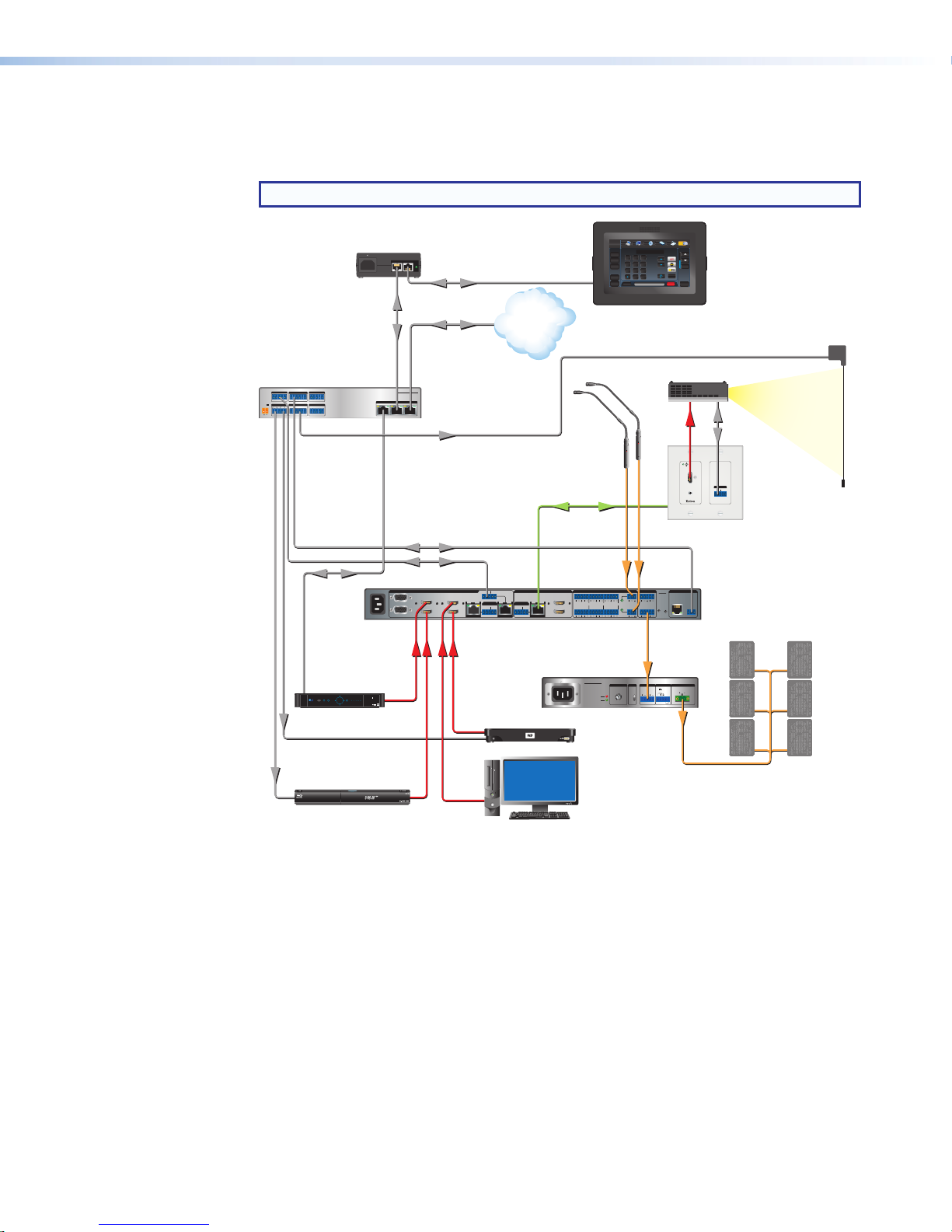
Application Diagram
Extron
Figure 1 shows a typical application for the TLP Pro 520M. The TLC Pro 521M can be used in
similar applications.
NOTE: The TLC Pro 521M does not require an external controller.
Extron
XTP PI 100
Power Injector
Extron
IPCP Pro 350
IP Link Pro
Control Processor
COM 1
COM 2
COM 3
G
Tx Rx RTSCTS
G
Tx Rx
Tx Rx
POWER
12V
RELAYS
IR/SERIAL
x.xA MAX
1
2
1 2 C
3 4 C
SG
SG
Doc
Tuner
1 2 3
VCRLaptop PC DVD
Cam
0
321
654
987
Enter
December 15, 2013 - 7:58 AM
Extron
Extron
Volume
Tuner
Channel
Presets
Last
Presets
System
Off
TLP Pro 520M
Mute
5" Wall Mount
More
Audio
Control
TouchLink Pro
Touchpanel
Screen Control
100-240V
50/60 Hz
---A MAX
Ethernet
XTP
XTP PWR
PWR
Ethernet/Power
Ethernet
TCP/IP
Network
Display
On
Off
Mute
Room
Control
Screen
Lighting
Help
Microphones
DIGITAL I/O
1 2 3 4 G
G
eBUS
+V+S-SG
PWR OUT = 6W
IPCP PRO 350
LAN
123
Relay
CATx Cable
up to 230' (70 m)
HDMI RS-232
OUTPUTS
AUDIO
OVER DTP
RS-232 IR
TxRx GTxRx
Extron
DTP HDMI
230 D Rx
Receiver
RS-232
Ethernet
PUSH PUSH
POWER GUIDE MENU RES480480p 720p1080i 1080p
SELECT
DIRECTV
Tuner
IR
RS-232
100-240V ~ -- A MAX
50/60 Hz
1
2
CONFIGURABLE
INPUTS
3
HDMI
4
HDMI HDMI
DIRECTV HD
5
HDMI
6
RS-232 IR
7
TxRx TxRxG
8
SIG LINK
SIG LINK
OVER DTPOVER DTP
RS-232 IR
DTP IN
DTP IN
TxRx TxRxG
Media Player
OUTPUTS
C
A
SIG LINK
L1
R
HDMI
RS-232 IR
TxRx TxRxG
L2
R
B
DTP OUT
Extron
XPA 2001-70V
Power Amplier
100-240V 0.5A, 50-60Hz
XPA 2001-70V
LIMITER/PROTECT
1
AUDIO INPUTS OUTPUTSOUTPUTS
L3
L4
SIGNAL
Audio
IN1608
12
1
+48V
L5
R
R
MIC/LINE
VARIABLE
RESET
2
L6
R
R
LR
+48V
Audio
REMOTE
INPUTS
ATTENUATION HPF
10V
L (SUMMED) R
10
12
8
6
14
80 Hz
18
4
2
26
OFF
0
∞
Audio
Blu-ray Player
IR
PC
Extron
REMOTE
IN1608
LAN
RS-232
Scaling Presentation
TxRx
G
Switcher
70 V OUTPUT
50mA
G
STANDBY
GCV
CLASS 2 WIRING
Extron
SM 26T
Surface Mount
Speakers
Figure 1. TLP Pro 520M Application Diagram
TLP Pro 520M and TLC Pro 521M • Introduction 3

Installation
Overview
This section contains an overview of the installation process. Follow the links for a more
detailed explanation of each step.
1. Before starting, download and install the latest versions of the following software:
GUI Designer — for designing layouts for Extron TouchLink Pro touchpanels and
third party touch interfaces.
Global Configurator Plus and Professional — for setting up and configuring
IPL Pro controllers, MediaLink Plus control processors, and TouchLink Pro devices.
NOTE: The TLC Pro 521M has an integrated controller. No external controller is
required.
Toolbelt — provides device discovery, device information, firmware updates,
and configuration of network settings, system utilities, and user management for
TouchLink Pro devices.
See Configuration Software on page 19.
2. Obtain the following network information from your network administrator:
DHCP status (on or off). If DHCP is off, you will also require:
IP address
Subnet mask
Gateway
User name — By default these are either admin or user.
Passwords — By default these are extron (for both admin and user).
MAC address — Make a note of the touchpanel MAC address, which can be found
on the rear panel label.
3. Mount and cable the units:
ATTENTION:
• Do not power on the touchpanels or control processors until you have read the
• Ne branchez pas les écrans tactiles ou les contrôleurs avant d’avoir lu les mises
Mount the units. There are several mounting options for Touchlink Pro touchpanels
(see Mounting on page 23).
Connect cables to the touchpanels (see TLP Pro 520M and TLC Pro 521M Rear
Panel Features on page 8).
Connect the power cords and power on all devices (see Power connector on
page8 or Network and Power over Ethernet (PoE) Connector on page 11).
Attention notice on page 9 (12 VDC power supply) or on page 12 (PoE injector).
en garde page9 (source d’alimentation 12VCC) ou page12 (injecteur PoE).
TLP Pro 520M and TLC Pro 521M • Installation Overview 4

4. Set up the Touchpanels for Network Communication:
Connect the PC that you will use for setup and the touchpanel to the same Ethernet
subnetwork. The TLP Pro 520M, also requires a control processor on the same
Ethernet subnetwork.
Use the Setup Menu (see page 14) or Toolbelt to set the DHCP status and, if
necessary, the IP address, subnet mask, gateway address, and related settings for
the touchpanel.
5. Configure the Touchpanels — The GUI Designer Help File, Global Configurator Help File,
and the Toolbelt Help File provide step-by-step instructions and more detailed information.
The Global Configurator Help File includes an introduction to the software and sections on
how to start a project and configuration.
TLP Pro 520M and TLC Pro 521M • Installation Overview 5

Panel Features
E
F
G
H
A
E
This section describes:
• TLP Pro 520M and TLC Pro 521M Front Panel Features
• TLP Pro 520M and TLC Pro 521M Rear Panel Features
TLP Pro 520M and TLC Pro 521M Front Panel Features
Figure 2 shows the front panel features for the TLP Pro 520M. The TLC Pro 521M is identical.
CDB
Figure 2. TLP Pro 520M Bezel (left) and Front Panel without Bezel (right)
Bezel
A
Communication LED (used only by
B
TLP Pro 520M)
Motion Sensor
C
Ambient Light Sensor
D
E
F
G
H
Status Lights
LCD Screen
Speaker
Menu Button
TLP Pro 520M and TLC Pro 521M • Panel Features 6

Bezel (see figure 2 on the previous page) — The TLP Pro 520M and TLC Pro 521M
A
ship with a black front bezel in the landscape orientation. If required, use the included
removal tool to detach the bezel. Accessory kits, which must be purchased separately, are
available for white bezels and bezels in the portrait orientation.
Remove the bezel by inserting
Display
On
Off
Mute
Room
Control
Screen
Control
Lighting
Control
Help
Laptop PC DVD
DVD
Menu Title
Enter
Audio
Mute
Control
Extron
System
Off
the provided Extron pry tool into
one of the notches on the bottom
surface of the bezel. Slowly move
the tool along the edge to separate
the bezel from the frame of the
touchpanel.
The notches are on the bottom
surface of both the landscape and
Doc
Tuner
1 2 3
VCRLaptop PC DVD
Cam
Display
On
Off
Mute
Room
Control
Screen
Lighting
Tuner
321
654
987
Enter
0
December 15, 2013 - 7:58 AM
Help
Extron
Extron
Volume
Channel
Presets
Mute
Last
More
Presets
System
Audio
Control
Off
portrait bezels (see the figure to the
right).
Communication LED (used only by TLP Pro 520M)— Shows the configuration and
B
connection status of the touchpanel:
• Unlit during normal operation (the touchpanel is configured and connected to an
IPLink Pro control processor).
• Blinks red if the touchpanel has been configured but is not connected to an
IPLinkPro control processor.
• Permanently lit if the touchpanel has not been configured.
Use the setup menu (see page 14) to toggle the indicator between enabled and disabled.
Motion sensor — Detects motion between three to five feet from the touchpanel and at
C
least 15° from the center axis.
• When no motion has been detected for a user-defined period of time, the screen
display enters into sleep mode.
• When motion is detected by the sensor, the screen display is restored and active.
Ambient light sensor — Monitors ambient light level and adjusts screen brightness,
D
based on the settings configured using the setup menu (see page 14).
Status lights — One on each side can be programmed to provide system feedback.
E
• Light red or green
• Blink or light continuously
For information about programming this light, see the Global Configurator Help File.
LCD screen — The 5-inch LCD capacitive glass touchscreen has a 800x480 resolution.
F
Speaker — One, located under the screen, provides audible feedback for the user. The
G
speaker grill is in the bottom surface of the bezel (see the arrow in figure 2, G).
Menu button — Activates the setup menu (see page14). The button is in a recessed
H
slot in the bottom surface of the touchpanel, directly under the Menu text (see the arrow in
figure 2,H).
TLP Pro 520M and TLC Pro 521M • Panel Features 7

TLP Pro 520M and TLC Pro 521M Rear Panel Features
TLP Pro 520M TLC Pro 521M
The rear panels of the TLP Pro 520M and TLC Pro 521M are identical except for the RS-232,
Relay, and IR/S ports on the TLC Pro 521M.
CED
A
B
RS-232 Relay IR/S
Tx Rx G1 2 CS G
F
G
H
Figure 3. TLP Pro 520M and TLC Pro 521M Rear Panel Features
Power connector
A
Digital input monitoring port (page 10)
B
RS-232 Connector (TLC Pro 521M only)
C
(page 10)
Relay Connector (TLC Pro 521M only)
D
(page 10)
ATTENTION:
• Do not power on the touchpanels or control processors until you have read the
Attention notice on page 9 (12 VDC power supply) or on page 12 (PoE injector).
• Ne branchez pas les écrans tactiles ou les contrôleurs avant d’avoir lu les mises en
garde page9 (source d’alimentation 12VCC) ou page12 (injecteur PoE).
IR/S Connector (TLC Pro 521M only)
E
(page 11)
Reset LED (page 11)
F
Reset button (page 11)
G
Network and Power over Ethernet
H
(PoE) connector (page 11)
Power connector — Connect this 2-pole, 3.5 mm captive screw receptacle to a
A
12VDC, 1.0 A power supply (not provided). Extron recommends the PS 1210C power
supply.
Ensure the connections have the correct polarity as shown in figure 4 (on the following
page).
WARNING: The two power cord wires must be kept separate while the power
supply is plugged in. Remove power before wiring.
AVERTISSEMENT : Les deux cordons d’alimentation doivent être tenus à l’écart
l’un de l’autre quand l’alimentation est branchée. Couper l’alimentation avant de faire
l’installation électrique.
NOTE: The TLP Pro 520M and TLC Pro 521M are shipped without a power supply.
Either the 12 VDC power supply or the PoE injector must be purchased separately.
TLP Pro 520M and TLC Pro 521M • Panel Features 8

Power Receptacle
(5 mm) Max.
+
POWER
12V
1.0A MAX
+
POWER
12V
1.0A MAX
Smooth
Ridges
AA
Captive Screw Connector
Ground
+12 VDC
AC Power Cord
Power Supply
Output Cord
External
Power Supply
(12 VDC, 1 A )
SECTION A–A
3/16"
Figure 4. Power Supply Connector
ATTENTION:
• Always use a power supply provided by or specified by Extron. Use of an
unauthorized power supply voids all regulatory compliance certification and may
cause damage to the supply and the end product.
• Utilisez toujours une source d’alimentation fournie ou recommandée par Extron.
L’utilisation d’une source d’alimentation non autorisée annule toute conformité
réglementaire et peut endommager la source d’alimentation ainsi que le produit
final.
• This product is intended for use with a UL Listed power source marked “Class 2”
or “LPS” and rated 12VDC, minimum 1.0 A. or 48 VDC (PoE), minimum 0.35 A.
• Ce produit est destiné à une utilisation avec une source d’alimentation listéeUL
avec l’appellation «Classe2» ou «LPS» et normée 12Vcc, 1,0A minimum ou
48Vcc (PoE), 0,35A minimum.
• Extron power supplies are certified to UL/CSA 60950-1 and are classified as LPS
(Limited Power Source). Use of a non-LPS or unlisted power supply will void all
regulatory compliance certification.
• Les sources d’alimentation Extron sont qualifiées UL/CSA60950-1 et sont
classéesLPS(LimitedPowerSource). L’utilisation d’une source d’alimentation
non-listée ou non-listéeLPS annulera toute certification de conformité
réglementaire.
• Unless otherwise stated, the AC/DC adapters are not suitable for use in air
handling spaces or in wall cavities. The power supply is to be located within the
same vicinity as the Extron AV processing equipment in an ordinary location,
Pollution Degree 2, secured to the equipment rack within the dedicated closet,
podium, or desk.
• Sauf mention contraire, les adaptateurs AC/DC ne sont pas appropriés pour
une utilisation dans les espaces d’aération ou dans les cavités murales. La
source d’alimentation doit être située à proximité de l’équipement de traitement
audiovisuel dans un endroit ordinaire, avec un degré2 de pollution, fixé à un
équipement de rack à l’intérieur d’un placard, d’une estrade, ou d’un bureau.
• The installation must always be in accordance with the applicable provisions of
National Electrical Code ANSI/NFPA 70, article 725 and the Canadian Electrical
Code part 1, section 16.
• Cette installation doit toujours être en accord avec les mesures qui s’applique
au National Electrical Code ANSI/NFPA70, article725, et au Canadian Electrical
Code, partie1, section16.
TLP Pro 520M and TLC Pro 521M • Panel Features 9

ATTENTION:
Equipment
A
ar
normally
open.
INPUT
RS-232
TxRx G
• The power supply shall not be permanently fixed to building structure or similar
structure.
• La source d’alimentation ne devra pas être fixée de façon permanente à une
structure de bâtiment ou à une structure similaire.
• The length of the exposed wires in the stripping process is critical. The ideal
length is 3/16 inches (5 mm). If the wires are any longer, the exposed wires may
touch, causing a short circuit between them. If they are any shorter, the wires can
be easily pulled out even if tightly fastened by the captive screws.
• La longueur des câbles exposés est primordiale lorsque l’on entreprend de les
dénuder. La longueur idéale est de 5mm (3/16inches). S’ils sont un peu plus
longs, les câbles exposés pourraient se toucher et provoquer un court circuit.
S’ils sont un peu plus courts, ils pourraient sortir, même s’ils sont attachés par les
vis captives.
NOTE: Do not tin the wires. Tinned wire does not hold its shape and can become
loose over time.
Digital input monitoring port (see figure 3 on page 8) — To monitor external
B
devices that do not use RS-232 communication, connect a switch, motion
sensor, moisture sensor, tally feedback output, button pad, or a similar item to
the digital I/O port and configure it for digital input. When configured, this two-
pole captive screw port (signal [1] and ground [G]) monitors digital input with
or without a +5 VDC pull-up.
RS-232 connector (TLC Pro 521M only, see figure 3)— This three-pole
C
3.5 mm captive screw connector supports software flow control.
Pin 1=Tx, Pin 2=Rx, Pin 3=G.
Serial protocol:
• 300 to 115200 baud (9600 baud = default) • 8 (default) or 7 data bits
• No parity (default), even, odd, mark, or space parity • 1 (default) or 2 stop bits
Relay connector (TLC Pro 521M only, see figure 3)— This three-pole 3.5 mm captive
D
screw connector provides normally open (NO) contact closure control for power to screen
or projector lifts, window coverings, or similar items.
Common
Normally
Open (1)
21C
RELAY
Do not exceed a total
of 24V at 1A for each
relay port.
Common
Relay 2
Relay 1
To Room
Control
ll relays
e
Common
Normally
Open (2)
Figure 5. TLC Pro 521M Relay Connectors
Pin 1= relay 1, Pin 2= relay 2, Pin C= Common.
The ports can be configured to operate in one of two ways:
• Latching (brief or indefinite period contact) (press to close, press to open), or
• Pulsed (timed cycle) (press to close, timeout to open, with automatic repeat). In pulse
mode the timeout period can be configured with Global Configurator. By default, this
period is 0.5 seconds.
NOTE: The pulse function is absolute: it always sets the relay state to closed,
times out (briefly), then opens the contact. It overrides the previously selected
setting (on state, off state, or toggle).
TLP Pro 520M and TLC Pro 521M • Panel Features 10

IR/S connector (TLC Pro 521M only, see figure 3)— This two-pole 3.5 mm captive
IR/S
IR/S
the IR Receiver of a
Two Single IR Emitters
Source Device
RJ-45
Connector
PC
T
LAN Port
E
screw connector can be configured to operate as a unidirectional serial port (figure 6, 1)
or an IR port (figure 6, 2). Pin 1= Signal (S), Pin 2= Ground (G).
IR/Serial Ports
Output options:
• IR (30 kHz to 300 kHz,
with or without carrier signals)
• Unidirectional RS-232
(-)
(+)
(-)
(-)
(+)
(+)
To
Projector, Display, or
Source Device
To a Projector,
Panel Display, or the
Wired IR Remote or
RS-232 Port of a
IR or RS-232 Output
Ground
SG
SG
or
1122
G
Unidirectional
IR
Ground
IR Output Signal
S
Figure 6. TLC Pro 521M IR/S Connector
• Serial port: Connect the port to the serial control receive (Rx) and ground pins of the
device to be controlled. The protocols are the same as the RS-232 connectors on the
previous page.
• IR control: Connect this port directly to the wired IR port of another device. Or insert
the wires from up to four IR Emitters into an IR port and place the heads of the
emitters over or next to the IR signal pickup windows of the devices.
NOTE: For the best IR control results, each emitter must be within 100 feet
(30 meters) of the TLC Pro 521M.
Reset LED — This LED is in the center of the rear panel, to the right of the reset button. It
F
indicates power status and reset status of the device (see Reset Modes on page 26).
Reset button — This recessed button is to the left of the Reset LED. Pressing the button
G
initiates the reset modes for the unit (see Reset Modes).
Network and Power over Ethernet (PoE) Connector — This connector is in the right
H
side of the recessed area.
Connect the touchpanel to the
LAN using a twisted pair cable,
terminated with an RJ-45
connector. Use a straightthrough Ethernet cable to
connect the panel to a switch
or router. Use a crossover
cable to connect the panel
directly to a computer.
An Extron IPL Pro Control
Processor must also be
connected to the same
network domain as the
TLPPro520M (see
www.extron.com for a list of
suggested models).
The TLC Pro 521M has an
integrated controller. No
external controller is required.
ouchpanel
TCP/IP
Network
Ethernet
Insert Twisted
Pair Wires
Pins:
12345678
Extron Devices
(Switchers, Scalers)
IPL Pro Controller
(TLP Pro 520M only)
Crossover Cable
(for direct connection to a PC)
End 1 End 2
Pin Wire Color Pin Wire Color
1 white-orange 1 white-green
2 orange 2 green
3 white-green 3 white-orange
4 blue 4 blue
5 white-blue 5 white-blue
6 green 6 orange
7 white-brown 7 white-brown
8 brown 8 brown
T568B T568A
Default protocol, public ports:
• TLC Pro 521M IP address: 192.168.254.252
• TLP Pro 520M IP address: 192.168.254.251
• Gateway IP address: 0.0.0.0
• Subnet mask: 255.255.255.0
• DNS address: 127.0.0.1
• DHCP: off • DNS: 127.0.0.1
LAN (Ethernet)
Figure 7. Network and PoE Connector
TLP Pro 520M and TLC Pro 521M • Panel Features 11

The network port has two LEDs:
or TLC Pro 521M
• The green LED lights steadily to show that the touchpanel is connected correctly to a
network.
• The amber LED flashes to show that data is being passed to or from the touchpanel.
The connector can also be used with a PoE power injector (not provided). Use any power
injector that is PoE+ IEEE 802.3af compliant. Extron recommends using the XTP PI 100
power injector, which is shown in figure 8 below. Your power injector may look different.
To use a power injector: Connect a straight-through Ethernet cable to the power supply
and a switch or router. This cable carries network information from the switch or router to
the power supply input. A second straight-through cable carries the network information
and 48VDC from the power supply to the touchpanel. Connect the IEC power cord to a
100 VAC to 240 VAC, 50-60 Hz power source.
100-240V ~ 50-60Hz
0.4A MAX
To network switchTo TLP Pro 520M
XTP
XTP PWR
PWR
Figure 8. Connecting the Power Injector
ATTENTION:
• The TLP Pro 520M and TLC Pro 521M are intended for connection to a Power
over Ethernet circuit for intra-building use only and are considered to be part of a
Network Environment 0 per IEC TR62101.
• Le TLP Pro 520M et le TLC Pro 521M sont conçu pour une connexion à un circuit
PoE pour une utilisation intérieure seulement et est considéré comme faisant
partie d’un environnement réseau 0 par IECTR62101.
• Always use a power supply provided by or specified by Extron. Use of an
unauthorized power supply voids all regulatory compliance certification and may
cause damage to the supply and the end product.
• Utilisez toujours une source d’alimentation fournie ou recommandée par Extron.
L’utilisation d’une source d’alimentation non autorisée annule toute conformité
réglementaire et peut endommager la source d’alimentation ainsi que le produit
final.
• This product is intended for use with a UL Listed power source marked “Class 2”
or “LPS” and rated 12VDC, minimum 1.0 A. or 48 VDC (PoE), minimum 0.35 A.
• Ce produit est destiné à une utilisation avec une source d’alimentation listéeUL
avec l’appellation «Classe2» ou «LPS» et normée 12Vcc, 1,0A minimum ou
48Vcc (PoE), 0,35A minimum.
• Extron power supplies are certified to UL/CSA 60950-1 and are classified as LPS
(Limited Power Source). Use of a non-LPS or unlisted power supply will void all
regulatory compliance certification.
• Les sources d’alimentation Extron sont qualifiées UL/CSA60950-1 et sont
classéesLPS(LimitedPowerSource). L’utilisation d’une source d’alimentation
non-listée ou non-listéeLPS annulera toute certification de conformité
réglementaire.
TLP Pro 520M and TLC Pro 521M • Panel Features 12

ATTENTION:
• Unless otherwise stated, the AC/DC adapters are not suitable for use in air
handling spaces or in wall cavities. The power supply is to be located within the
same vicinity as the Extron AV processing equipment in an ordinary location,
Pollution Degree 2, secured to the equipment rack within the dedicated closet,
podium, or desk.
• Sauf mention contraire, les adaptateurs AC/DC ne sont pas appropriés pour
une utilisation dans les espaces d’aération ou dans les cavités murales. La
source d’alimentation doit être située à proximité de l’équipement de traitement
audiovisuel dans un endroit ordinaire, avec un degré2 de pollution, fixé à un
équipement de rack à l’intérieur d’un placard, d’une estrade, ou d’un bureau.
• Power over Ethernet (PoE) is intended for indoor use only. It is to be connected
only to networks or circuits that are not routed to the outside plant or building.
• L’alimentation via Ethernet (PoE) est destinée à une utilisation en intérieur
uniquement. Elle doit être connectée seulement à des réseaux ou des circuits qui
ne sont pas routés au réseau ou au bâtiment extérieur.
• The installation must always be in accordance with the applicable provisions of
National Electrical Code ANSI/NFPA 70, article 725 and the Canadian Electrical
Code part 1, section 16.
• Cette installation doit toujours être en accord avec les mesures qui s’applique
au National Electrical Code ANSI/NFPA70, article725, et au Canadian Electrical
Code, partie1, section16.
• The power supply shall not be permanently fixed to building structure or similar
structure.
• La source d’alimentation ne devra pas être fixée de façon permanente à une
structure de bâtiment ou à une structure similaire.
TLP Pro 520M and TLC Pro 521M • Panel Features 13

On-screen Menus
This section describes the setup menu. The screens shown are for the TLP Pro 520M. The
screens for the TLC Pro 521M are similar. Where there are differences, the screens for both
products are shown.
Setup Menu
To access the setup menu, insert a small screwdriver into the recess on the bottom of the front
panel and press the Menu button (see figure 2 H, on page 6).
The menu opens at the Status screen. There are five different screens (Status, Network,
Display, Audio, and Advanced). These can be selected by pressing the appropriate button
in the navigation panel at the top of the screen. The button for the selected screen is shown in
yellow. The buttons for the remaining screens are shown in black.
There is also a red Exit button in the top right corner of the screen. Pressing this button
applies and saves any changes and closes the menu screens.
In this section, the figures will show the screens for the TLP Pro 520M. The screens for the
TLC Pro 521M are similar.
Status Screen
This screen opens by default. To access the Status screen from any other part of the Setup
menu, press Status in the top menu bar.
There are small differences between the TLP Pro 520M and the TLC Pro 521M, which are
shown in figure 9.
Status
Network
Display Audio Advanced Exit
Status
Network
Display Audio Advanced Exit
Info
Model: TLC Pro 520M
Part Number: 60-1185-02
Firmware
Version:
Touchscreen
Version:
Bootloader
Version:
PoE: Active
1.00
2438
1.03.0000
Network
IP Address:
192.168.254.251
DHCP:
Off
Host Name:
TLP-AB-CD-EF
Audio
Master Volume:
Master Mute: Off
Display
Resolution:
Project:
Sleep Timer:
99
Controller IP: N/A
Project Size: N/A
800x480
N/A
5 Minutes
Advanced
Info
Model: TLC Pro 521M
Part Number: 60-1284-02
Firmware
Version:
Touchscreen
Version:
Bootloader
Version:
PoE: Active
1.00
2438
1.03.0000
Network
IP Address:
192.168.254.252
DHCP:
Off
Host Name:
TLP-AB-CD-EF
Audio
Master Volume:
Master Mute: Off
99
Display
Resolution:
Project:
Sleep Timer:
Advanced
Project Size: N/A
800x480
N/A
5 Minutes
Figure 9. Status Screen: TLP Pro 520M (left) TLC Pro 521M (right)
The Status screen is read-only. The Info panel provides basic information about the
touchpanel. Each of the other four panels shows a summary of the information on the
corresponding screen. Pressing any of those four panels opens that screen in exactly the same
way as pressing the buttons in the top navigation panel.
The bubble in the Network panel lights green when there is a network connection or a red
square is shown if there is no connection. The bubble in the Advanced panel (TLP Pro 520M
only) lights green when a control processor is connected. A red square is shown if no control
processor is connected.
TLP Pro 520M and TLC Pro 521M • On-screen Menus 14

Network Screen
To open the Network screen, click Network in the top menu bar.
Verify with your network administrator whether the IP address for the touchpanel is assigned
by DHCP or set manually. If they are set manually, you need to obtain an IP address, a subnet
mask, a gateway address, and a Domain Name Server (DNS) IP address from the network
administrator.
Status
Network
Display Audio Advanced Exit
DHCP
On Off
Host Name:DNS Primary:
IP Address:
Subnet Mask:
Gateway:
TLP-AB-CD-EF
192.168.254.251
255.255.255.0
0.0.0.0
Domain Name:
MAC Address:
127.0.0.1
00-05-A6-AB-CD-EF
Revert Apply
Figure 10. Network Screen
1. If IP addresses are assigned by DHCP, press On. The selected button is highlighted in
yellow. If DHCP is selected, you are able to set only the Host Name and DNS IP address.
All other values are set by the DHCP server.
If IP addresses are assigned manually, press Off. When DHCP is off, all values can be
edited.
2. Edit the Host Name by pressing that button. A keypad opens:
Figure 11. Alphanumeric Keyboard
• Use the keypad to enter a new name, which appears in the Host Name text box.
• Use the backspace character (
• The right and left arrow keys move the cursor inside the Host Name text box.
• Press the Shift key to toggle between the upper and lower case letters.
• Press Enter to save the new name.
3. If DHCP is disabled, set the unit IP address, subnet mask, gateway address, and
) to delete existing characters.
x
TLP Pro 520M and TLC Pro 521M • On-screen Menus 15

DNSserver address.
a. Press the button for the address to be edited. A screen opens, showing the
address and a numerical keypad.
IP Address
192 168 254 251
Clear
1
4
7
Back
3
2
6
5
98
0
OK
Cancel
Figure 12. Numerical Keypad for Setting IP Addresses
b. Press Clear to remove the old address. If you start typing without pressing
Clear, the first octet is overwritten and the other octets remain the same.
c. Click any octet button to start editing that octet.
d. Enter a 3-digit value for the octet (leading zeroes in the octet are ignored).
NOTE: Octets can have any value between 0 and 255. If you attempt to enter an
invalid number, for example 892, you are able to enter the 89 but the 2 cannot
be entered.
Click Back to correct the last digit entered. If no value has been entered for the
selected octet, clicking Back moves the cursor back to the previous octet and
deletes the last digit of that octet.
e. Click the next octet button and enter a value.
f. Repeat steps c-e until values have been entered for all four
octets.
0.0.0.10
g. Press OK to save the changes and return to the Network
screen or press Cancel to return to the Network screen
without saving the changes.
4. If you have changed any of the values in the Network screen, the background color of the
button changes to blue (as shown in the figure to the right). Click Apply to apply the new
values or Revert to return to the previous values without saving the changes. The buttons
change back to gray.
If you have not made any changes, the Apply and Revert buttons are grayed out.
TLP Pro 520M and TLC Pro 521M • On-screen Menus 16

Display Screen
Status
Network
Sleep Timer
2
3
4
Minutes
On Off
Display Audio Advanced Exit
Auto Brightness
On Off
LCD Brightness
050100
Wake on Motion
On Off
Figure 13. Display Screen
To open the Display screen, click Display in the top menu bar. The Display screen allows
you to set the Sleep Timer, Auto Brightness, LCDBrightness, and Wake on Motion.
• Sleep Timer — Determines how long the panel will be inactive before it enters Sleep
mode, when the screen goes dark to save power. Toggle between On and Off. If the
sleep timer is On, use the arrows to adjust the value between 1 and 120 minutes.
• Auto Brightness — Provides a suitable amount of backlighting that is automatically
calculated from the amount of ambient light detected by the light detector.
• LCD Brightness — Allows you to adjust the screen brightness, using the slider control.
• Wake on Motion — Activates the panel from Sleep mode when motion is detected near
the unit. Toggle between On and Off.
Audio Screen
Status
Network
Master
100
50
0
Figure 14. Audio Screen
To open the Audio screen, click Audio in the top menu bar. On the Audio screen, use the
slider controls to adjust the Master, Click, and Sound volume settings.
• Master volume sets the maximum threshold for both the other sound volume settings.
For example, if the Master volume is set to 80 (80 percent of maximum), even when the
Sound volume is set to 100, it is equivalent to only 80 percent of the absolute maximum.
• Click sets the volume for audible feedback that accompanies events such as a screen
button being pressed.
• Sounds sets the volume of audio from any audio file playback.
Display Audio Advanced E xit
Click
100
50
0
Sound
100
50
0
TLP Pro 520M and TLC Pro 521M • On-screen Menus 17

Advanced Screen
To open the Advanced screen, click Advanced in the top menu bar.
There are small differences between the TLP Pro 520M and the TLC Pro 521M, which are
shown in figure 15.
Status
Touchpanel Name:
Controller Name:
Controller IP:
------------------------------------------------------------Global Configurator Project
Name:NorthHall
Version: 01.00.1383
Creation Date:3/13/2014 2:48:20 PM
Revision Date:3/14/2014 4:15:45 PM
Network
System
TLP-AB-CD-EF
IPCP 505 - North Hall
192.168.254.11
Menu PIN
Off ChangeOn
Display Audio Advanced Exit
Name:
Resolution:
Creation Date:
Revision Date:
Version:
Project Size: 12 MB
Project Usage: 0%
GUI Project
Jet Video Conference System
800x480
2/12/2014
03/12/2014
01.00.16
115 MBStorage Size:
Communication LED
Enable Disable
Status
Controller Name:
Controller IP:
--------------------------------------------------------------------Global Configurator Project
Name:NorthHall
Version: 01.00.1383
Creation Date:3/13/2014 2:48:20 PM
Revision Date:3/14/2014 4:15:45 PM
---------------------------------------------------------------------
Project Size:12 MB
Project Usage: 0%
Network
System
TLC-AB-CD-EF
192.168.254.11
115 MBStorage Size:
Menu PIN
Off ChangeOn
Display Audio Advanced Exit
Name:
Resolution:
Creation Date:
Revision Date:
Version:
GUI Project
Jet Video Conference System
800x480
2/12/2014
03/12/2014
01.00.16
Figure 15. Advanced Screen: TLP Pro 520M (left) TLC Pro 521M (right)
System and GUI Project Panels
These panels are read only, providing information about the System, the Global
Configurator Project, and the GUIProject.
The Controller IP address for the TLP Pro 520M shows the IP address for the controller
connected to the touchpanel. The Controller IP address for the TLC Pro 521M is the TLC unit
itself.
Menu PIN
Click Change to open the PIN setup window. The PIN setup options allow you to enable,
disable, or change the setup menu PIN. The PIN is a 4-digit number. Each digit can have any
value from 0-9.
1. Select the first digit of the PIN. When selected, it is highlighted in yellow.
Enter New Menu PIN
213
Back
Figure 16. Numeric Keypad for Setting PIN
2. Press a number on the keypad. That number is the first digit of the PIN. It is shown as a
dot at the top of the window.
3. Repeat steps 1 and 2 for the other 3 digits.
4. The title bar changes to Confirm New Menu PIN.
5. Enter the PIN a second time. When the PIN entered on the second occasion matches the
PIN entered on the first occasion, the PIN is set and the dialog box closes.
Communication LED (TLP Pro 520M only)
The Communication LED (see figure 2, B on page 6) can be enabled or disabled by
pressing the Enable or Disable button. The Communication LED is not available for the
TLC Pro 521M.
456
8
7
0
9
Cancel
TLP Pro 520M and TLC Pro 521M • On-screen Menus 18

Configuration
Software
This section of the user guide provides information about:
• Configuration Software
• TLP Pro 520M and TLC Pro 521M Web Pages
• Updating Firmware
Configuration Software
Use Toolbelt to provide device information, firmware updates, and configuration of network
settings, system utilities (reset, reboot), and user management (username and password) for
TouchLink Pro devices.
Use GUI Designer and Global Configurator Plus and Professional to design a graphical user
interface (GUI) for the TouchLink Pro touchpanel:
1. Design the layout of the screen text and graphics using GUI Designer, which is a
Windows-based application. You can either customize an existing template or create an
entirely new interface. GUIDesigner offers several templates.
2. After the user interface has been designed, the project is saved, built, and imported into
Global Configurator Plus and Professional.
3. Use Global Configurator Plus and Professional to assign functions to the text and
graphics.
4. After assigning the control functions, the project is rebuilt and uploaded to the control
processor and touchpanel.
The GUI Designer and the Global Configurator Plus and Professional programs provide
versatility and adaptability for configuration and control of an AV system as it grows and
evolves.
TLP Pro 520M and TLC Pro 521M • Configuration Software 19

Installing GUI Designer, Global Configurator, and Toolbelt
NOTE: Use GUIDesigner and Global Configurator Plus and Professional to configure the
TLP Pro 520M or TLC Pro 521M.
GUI Designer, Global Configurator, and Toolbelt can be downloaded from www.extron.com.
1. Select the Download tab (
left.
) and click the Software option (2) in the sidebar at the
1
11
2
2
3
3
4
4
Figure 17. Downloading Software
2. Select the link to Global Configurator Plus and Professional (
(4), or Toolbelt. If they are not available on the Software home page, scroll down the
page to the alphabetic menu bar and click on the appropriate initial letter.
ALL #ABC DEFG HI JK MLNPOQ TSRUVWXYZ
Figure 18. Alphabet Software Menu
3. Scroll through the search results until you find it.
• GUI Designer — Click the Download button next to the program and follow the
on-screen instructions.
• Global Configurator — Ensure you are downloading Global Configurator Plus
and Professional. Click the Download button next to the program and follow the
on-screen instructions.
NOTES:
• You need an Extron Insider account to run Global Configurator Plus and
Professional. To obtain one, contact the Extron Sales Department.
• After downloading Global Configurator Plus and Professional, you have the
option to download Toolbelt without returning to the Extron Download page.
• Toolbelt — If you choose to download Global Configurator and Toolbelt separately,
click the Download button next to the program and follow the on-screen instructions.
), GUI Designer
3
TLP Pro 520M and TLC Pro 521M • Configuration Software 20

Using the Software
Extron Electronics
GUI Designer
Use the GUI Designer software to design the screen layout for the touchpanel. See the
GUIDesigner Help File for step-by-step instructions and more detailed information.
Global Configurator
Use the Global Configurator software to set up and configure the control processor and the
touchpanel. See the Global Configurator Help File for step-by-step instructions and more
detailed information. The Global Configurator Help File also includes an introduction to the
software and sections on how to start and configure a project.
Toolbelt
Use the Toolbelt software for device discovery, device information, firmware updates, and
configuration of network settings, system utilities, and user management for TouchLink Pro
devices (see the Toolbelt Help File for more detailed information).
TLP Pro 520M and TLC Pro 521M Web Page
To access the touchpanel default web pages, enter the IP address of the unit into the web
browser of a PC connected to the same subnet. There is a single, read-only page that
provides general and network information about the unit.
A dialog box opens asking for your user name and password. By default, the user name is
admin and the password is extron (both user name and password are all lower case).
The single page provides general and network information about the unit. It also allows you to
upgrade the unit firmware.
Use the Setup Menu (see page 14) or Toolbelt to configure the touchpanel network settings.
Figure 19 shows the TLP Pro 520M Web page. The TLC Pro 521M Web page is similar.
®
General Status
Model Name: TLP Pro 520M
Description: TouchLink Pro Wall Mount
Part Number: 60-1185-02
Firmware Version: 1.00
Date: Monday, May 27, 2013
Time:7:58 PM
POE: On
Up Time: 0 day(s) 1 hour(s) 23 minute(s)
License Information
System Devices
Device Name Part Number Hostname/IP
Firmware Upgrades
Firmware:
IP
DHCP: Off
Host Name: TLP-Pro-520M-AB-CD-EF
IPv4 IP Address: 192-168-254-251
DNS (IP): 127.0.0.1
Gateway IP:0.0.0.0
Subnet Mask: 255.255.255.0
Mac Address:00-05-A6-XX-XX-XX
Browse Upload
Project
No Project Configured
Figure 19. TLP Pro 520M Web Page
TLP Pro 520M and TLC Pro 521M • Configuration Software 21

Updating Firmware
Firmware for these touchpanels can be upgraded using Toolbelt or the touchpanel web page.
Before starting, consult your IT team and ensure that the touchpanel has a unique IP address.
Downloading Firmware
1. Power on a computer that is connected to the same network as the touchpanel.
2. On the Extron website, click Download in the menu bar along the top of the page (see
figure20,1).
2
2
11
3
3
Figure 20. Firmware Download Center
3. Click Firmware in the menu bar in the left side bar (
4. Click the letter T from the list of letters (
5. Scroll down the page until you find the firmware for your model.
6. Click Release Notes for more information about the firmware.
7. Click Download. The product download screen opens.
8. Enter the required information and click Download. An executable (.exe) file is downloaded
to your computer. Run this program to place the firmware on your computer for future use.
Make a note of the folder where the firmware is saved.
3
).
2
).
Updating Firmware Using the Touchpanel Web Page
1. If you have not already done so, download the firmware file to a computer on the same
network as the touchpanel (see Downloading Firmware, above).
2. Open the touchpanel web page (see TLP Pro 520M and TLC Pro 521M Web Page on
the previous page).
Figure 21. Touchpanel Web Page: Firmware Uploader
3. Click Browse and navigate to the firmware location (see step 8 above).
4. Click Upload. The firmware file is uploaded to the touchpanel. Follow the on-screen
instructions.
Updating Firmware Using Toolbelt
For complete information about using Toolbelt to update the touchpanel firmware, see the
Toolbelt Help File.
TLP Pro 520M and TLC Pro 521M • Configuration Software 22

Mounting
This section outlines the various options for:
• Wall or Furniture Mounting
• Other Mounting Options
Wall or Furniture Mounting
The illustrations in this section show the TLP Pro 520M. The TLC Pro 521M is mounted in the
same way.
ATTENTION:
• Do not install the TLP Pro 520M or the TLC Pro 521M in a fire resistant rated wall or
partition assembly.
• Ne pas installer le TLP Pro 520M ou le TLC Pro 521M dans un mur résistant au feu ou
une cloison.
• All structural steps and electrical installation must be performed by qualified personnel
in accordance with local and national building codes and electrical codes.
• Toute étape structurelle et installation électrique, doit être effectuée par un personnel
qualifié, conformément aux codes du bâtiment, aux codes incendie et sécurité, et aux
codes électriques, locaux et nationaux.
To mount the touchpanel directly into drywall, follow these steps. The steps are similar if the
unit is mounted in furniture (such as a podium or table).
1. Use the cut-out template (available from www.extron.com) to mark the wall at a suitable
location.
2. Use a wallboard saw or jigsaw to cut away the hole.
3. If there is insulation inside the drywall, remove at least 6inches (15 cm) of the insulation in
all directions around the opening.
4. Check the size of the opening by inserting the included wallplate adapter into it.
5. Use a Phillips head screwdriver to tighten the locking arm screws of the wallplate adapter
(see figure 22, 5 on the following page). As the screws tighten, the locking arms rotate
behind the wall and hold the adapter in place.
ATTENTION:
• Do not overtighten the screws as this can damage the catches or the wall.
• Ne serrez pas trop les vis au risque d’endommager les attaches ou le mur.
6. Route the cables, leaving enough slack to connect them to the back of the touchpanel.
7. Plug the cables into the rear panel connectors (see TLP Pro 520M and TLC Pro 521M
Rear Panel Features on page 8).
a. If required, insert captive screw connectors into the control ports.
b. Connect the LAN port to the PoE power injector or a PoE enabled switch.
c. If you use the LAN port only as a network connection, connect a 12 VDC, 1.0 A
power supply to the 2-pole captive screw power input connector.
d. Push excess cable into the wall cavity.
8. Press the touchpanel onto the wallplate adapter (
8
).
TLP Pro 520M and TLC Pro 521M • Mounting 23

9. Remove the bezel by inserting the provided Extron pry tool into one of the notches on the
bottom surface of the bezel (9). Slowly move the tool along the edge to separate the
bezel from the frame of the touchpanel. The notches are on the bottom surface of both
the landscape and portrait bezels.
10. Attach the touchpanel to the wallplate adapter with the two provided #4-40x¼” Phillips
head screws (¢). For extra security, use two security screws (not provided).
11. Reattach the bezel.
12. If required, perform the initial configuration, using the Setup Menu (see page 14).
TLP Pro 520M
Tighten screws to
5
rotate locking arms
and secure wallplate
adapter.
8
TLP Pro 520M snaps
to wallplate adapter
(2 places on each side).
Mounting
10
Screws (2)
Remove
9
Bezel.
Figure 22. Mounting the TLP Pro 520M
TLP Pro 520M and TLC Pro 521M • Mounting 24

Other Mounting Options
Extron provides a range of mounting kits for the TLP Pro 520M and TLC Pro 521M. These
allow the touchpanel to be mounted on glass surfaces, desktops (fixed or swivel mount), rack
mounted (see below for important guidelines about rack mounting), and wall mounted, with a
wall box.
See www.extron.com for the complete range of mounting options.
To mount the TLP Pro 520M or TLC Pro 521M, follow the instructions provided with the kit.
Underwriters Laboratories Guidelines for Rack Mounting
The following Underwriters Laboratories (UL) guidelines are relevant to the safe installation of
these products in a rack:
• Elevated operating ambient temperature — If the unit is installed in a closed or
multi-unit rack assembly, the operating ambient temperature of the rack environment
may be greater than room ambient temperature. Therefore, install the equipment in an
environment compatible with the maximum ambient temperature (Tma: +122 °F, +50 °C)
specified by Extron.
• Reduced air flow — Install the equipment in the rack so that the equipment gets
adequate air flow for safe operation.
• Mechanical loading — Mount the equipment in the rack so that uneven mechanical
loading does not create a hazardous condition.
• Circuit overloading — Connect the equipment to the supply circuit and consider the
effect that circuit overloading might have on overcurrent protection and supply wiring.
Give appropriate consideration to the equipment nameplate ratings when addressing this
concern.
• Reliable earthing (grounding) — Maintain reliable grounding of rack-mounted
equipment. Pay particular attention to supply connections other than direct connections to
the branch circuit (such as the use of power strips).
TLP Pro 520M and TLC Pro 521M • Mounting 25

Reference
Material
This section contains information about:
• Network Port Requirements and Licensed Third-Party Software Used in the
Touchpanels
• Reset Modes
Network Port Requirements and Licensed Third-Party Software Used
in the Touchpanels
For information about network port requirements and licensed third-party software for the
TLP Pro 520M or the TLC Pro 521M, please refer to the Pro Series Control Product Network
Ports and Licenses Guide, which is available at www.extron.com.
Reset Modes
The TLP Pro 520M and TLC Pro 521M share the following three reset modes.
• Use Factory Firmware
• Reset All IP Settings
• Reset to Factory Defaults
The TLC Pro 521M has a built-in controller and supports two additional modes
• Project Recovery
• Run or Stop Program
These two modes are listed second and third in this section to remain consistent with other
Extron controllers.
The reset modes are initiated by pressing the Reset button, which is found on the rear panel
(see figure 3, D on page 8).
Use Factory Firmware
This mode is used to boot up the unit with factory-installed firmware for a single power cycle
in the event of a firmware update that failed or incompatibility issues arising with user-loaded
firmware
Activation
To start the Use Factory Firmware reset mode and replace firmware:
1. On the touchpanel, hold down the recessed Reset button while applying power to the
unit. When power is restored, the Reset LED lights. Hold the Reset button for a further
two seconds before releasing it. The touchpanel enters factory firmware mode.
2. Upload new firmware to the unit as desired (see Updating Firmware on page 22).
NOTE: Do not continue to operate the touchpanel using the factory firmware version.
If you want to use the factory default firmware, you must upload that version again
(see Updating Firmware on page 22).
TLP Pro 520M and TLC Pro 521M • Reference Material 26

Result
The unit reverts to factory-installed firmware. Event scripting does not start if the unit is
powered on in this mode. All user files and settings such as drivers, adjustments, and IP
settings are maintained.
NOTE: To return the unit to the firmware version that was running prior to the reset, cycle
power to the unit.
Project Recovery (TLC Pro 521M Only)
This mode is used to recover project configuration and program files if passwords are lost.
Activation
To start the Project Recovery reset mode and recover a project:
1. On the PC, open Global Configurator.
2. Click the Tools menu and select Project Recovery. The Recovery Mode dialog box
opens.
3. Enter the IP address or host name of the target device for which you want to perform
project recovery.
4. Click Recover. The software allows indefinite time to establish a connection (until a
connection is made or the user clicks Cancel).
5. On the TLC Pro 521M, press the recessed Reset button three times within one second.
The TLC Pro 521M enters project recovery mode for 30 seconds, during which time the
Reset LED flashes quickly.
GC automatically connects to the TLC Pro 521M, then opens and retrieves the project
from the unit.
6. Cycle power to the TLC Pro 521M to exit project recovery mode.
7. Perform the Reset to Factory Defaults reset on the TLC Pro 521M (see the following
page).
8. Open Toolbelt, start device discovery, select the desired TLC Pro 521M from the list and
click Manage.
9. Click the Network Settings tab and set the IP address of the TLC Pro 521M.
10. Click the User Management tab and change the password of the TLC Pro 521M.
11. Close Toolbelt.
12. In GC, add the new password to the recovered project.
13. Save the project.
14. Upload the project from GC to the TLC Pro 521M.
Result
Project Recovery mode stops regular operation and allows a connection to be made to the
unit via GC software without requiring password entry so that project files can be retrieved and
saved.
• During product recovery mode, events are stopped, and so is communication with AV
devices.
• While the TLC Pro 521M is in this mode, use the GC software to recover project files.
• If the software does not initiate project recovery within 30 seconds after the control
processor enters this mode, the TLC Pro 521M exits recovery mode.
• Upon exiting project recovery mode:
• The unit returns to its pre-recovery mode state and settings.
• The Power LED returns to being steadily lit.
Run or Stop Program (TLC Pro 521C only)
This mode toggles between stopping and starting programs.
TLP Pro 520M and TLC Pro 521M • Reference Material 27

Activation
To toggle between stop and start:
1. Hold down the Reset button for approximately 3 seconds until the Power LED blinks
once.
2. Release and press Reset momentarily (for <1 second) within 1 second. Nothing happens
if the momentary press does not occur within 1 second.
Result
The LED flashes twice if the program is starting or three times if the program is stopping.
Reset All IP Settings
This mode resets all IP settings to factory defaults.
Activation
To reset all IP settings:
1. Hold down the Reset button for approximately 6 seconds until the Power LED blinks
twice (once at 3 seconds, again at 6 seconds).
2. Release and press Reset momentarily (for <1 second) within 1 second. Nothing happens
if the momentary press does not occur within 1 second.
Result
Reset All IP Settings mode:
• Sets the IP address back to factory default (192.168.254.251 for the TLP Pro 520M and
192.168.254.252 for the TLC Pro 521M).
• Sets the subnet back to factory default (255.255.255.0).
• Sets the default gateway address to the factory default (0.0.0.0).
• Sets all other IP settings, addresses, and domain and host names back to factory default.
• Turns DHCP off.
Reset to Factory Defaults
This mode resets all IP settings and touchpanel settings to factory defaults and removes all
configurations. It allows you to start over with configuration and uploading.
Activation
To reset the unit to all factory default settings:
1. Hold down the Reset button for approximately 9 seconds until the Power LED blinks
three times (once at 3 seconds, again at 6 seconds, again at 9 seconds).
2. Release and press Reset momentarily (for <1 second) within 1 second. Nothing happens
if the momentary press does not occur within 1 second.
Result
Reset to Factory Defaults mode performs a complete reset to factory defaults (except the
firmware).
• Does everything Reset All IP Settings mode does (see above).
• Removes touchpanel configurations and user interface.
• Resets all touchpanel settings to factory default.
TLP Pro 520M and TLC Pro 521M • Reference Material 28

Extron Warranty
Extron Electronics warrants this product against defects in materials and workmanship for a period of three years
from the date of purchase. In the event of malfunction during the warranty period attributable directly to faulty
workmanship and/or materials, Extron Electronics will, at its option, repair or replace said products or components,
to whatever extent it shall deem necessary to restore said product to proper operating condition, provided that it is
returned within the warranty period, with proof of purchase and description of malfunction to:
USA, Canada, South America,
and Central America:
Extron Electronics
1230 South Lewis Street
Anaheim, CA 92805
U.S.A.
Europe and Africa:
Extron Europe
Hanzeboulevard 10
3825 PH Amersfoort
The Netherlands
Japan:
Extron Electronics, Japan
Kyodo Building, 16 Ichibancho
Chiyoda-ku, Tokyo 102-0082
Japan
China:
Extron China
686 Ronghua Road
Songjiang District
Shanghai 201611
China
Asia:
Extron Electronics Asia Pte. Ltd.
135 Joo Seng Road, #04-01
PM Industrial Bldg.
Singapore 368363
Middle East:
Extron Middle East
Dubai Airport Free Zone
F13, PO Box 293666
Dubai, United Arab Emirates
Singapore
This Limited Warranty does not apply if the fault has been caused by misuse, improper handling care, electrical
or mechanical abuse, abnormal operating conditions, or if modifications were made to the product that were not
authorized by Extron.
NOTE: If a product is defective, please call Extron and ask for an Application Engineer to receive an RA (Return
Authorization) number. This will begin the repair process.
USA: 714.491.1500 or 800.633.9876 Europe: 31.33.453.4040
Asia: 65.6383.4400 Japan: 81.3.3511.7655
Units must be returned insured, with shipping charges prepaid. If not insured, you assume the risk of loss or damage
during shipment. Returned units must include the serial number and a description of the problem, as well as the
name of the person to contact in case there are any questions.
Extron Electronics makes no further warranties either expressed or implied with respect to the product and its quality,
performance, merchantability, or fitness for any particular use. In no event will Extron Electronics be liable for direct,
indirect, or consequential damages resulting from any defect in this product even if Extron Electronics has been
advised of such damage.
Please note that laws vary from state to state and country to country, and that some provisions of this warranty may
not apply to you.
Extron Headquarters
+1.800.633.9876 (Inside USA/Canada Only)
Extron USA - West Extron USA - East
+1.714.491.1500 +1.919.850.1000
+1.714.491.1517 FAX +1.919.850.1001 FAX
Extron Europe
+800.3987.6673
(Inside Europe Only)
+31.33.453.4040
+31.33.453.4050 FAX
© 2016 Extron Electronics All rights reserved. www.extron.com
Extron Asia
+65.6383.4400
+65.6383.4664 FAX
Extron Japan
+81.3.3511.7655
+81.3.3511.7656 FAX
Extron China
+86.21.3760.1568
+86.21.3760.1566 FAX
Extron Middle East
+971.4.299.1800
+971.4.299.1880 FAX
Extron Korea
+82.2.3444.1571
+82.2.3444.1575 FAX
Extron India
1800.3070.3777
(Inside India Only)
+91.80.3055.3777
+91.80.3055.3737 FAX
 Loading...