


MulTI-Touch
Projected Capacitive Touch Screen
Integration Guide
Document Number: 6500493 Rev. 1.1 Pg. 1

The information provided in this document is intended as a guide only and is subject to change without
notice. Touch International is committed to continually advancing product designs; therefore, product specifications
may be subject to change without notification. Please contact your Touch International Sales Representative for th e
most recent specification.
– COPYRIGHT –
This document is the sole property of Touch International. The information contained within is Proprietary and may
not be reproduced or disclosed to third parties without the prior written consent of Touch International. Touch
International may have patents or pending patent applications, trademarks, copyrights or other intellectual property
rights covering subject matter in this document.
– IMPORTANT NOTICE –
A variety of factors can affect the performance and use of Touch International products. The customer is responsible
for evaluating the product and software to insure it is suitable for the intended application. Touch International
statements, engineering/technical information and recommendations are provided for the user’s convenience, but
their accuracy or completeness is not warranted.
Specifications are subject to change without notice. Touch International products and software are warranted to meet
their published specifications from the date of shipment and for the period stated in the specification.
The customer is responsible for determining whether the Touch International products and software are applicable to
the application and is suitable for its production process. In the event of a defective produ ct, Touch International is
only obligated to cover failures due to defects in materials or workmanship that occur in normal use. Touch
International is not obligated to cover damage that occurs in shipment, failures that are caused by products not
supplied by Touch International, failures that result from accident, misuse, abuse, neglect, water damage,
mishandling, misapplication, faulty installation, set-up adjustments, improper maintenance, alteration, line power
surge, external product damage including field damage, modification or service not approved by Touch International
or damage that is attributable to acts of God.
Copyright © 2011 - Touch International - All Rights Reserved
Last Revision Date: 5/03/2011
Document Number: 6500493
Revision: 1.0
Document Number: 6500493 Rev. 1.1 Pg. 2

Document Revision History
Revision Page Content Revised By Date
1.0 1-13 Initial Release Mani Thangaraju 5/3/2011
1.1 1-13 Revision/Logo/Etc. Shaun Detmer 4/20/2014
Document Number: 6500493 Rev. 1.1 Pg. 3
1.0 Manual Introduction
1.1 Safety
This symbol indicates potential hazards that can harm personnel.
1.2 Terms
The following terms and abbreviations may be unfamiliar and may appear in the manual. As such, they are
defined in Table 1.
This symbol indicates potential hazards that can damage the product.
Viewing Area
Active Area
Underlay
ESD
VHB
EMI
RFI
This is the area of the Touch Screen that is visible after a bezel is mounted.
This is the area of the Touch Screen that will recognize a touch event.
A graphic to define keys and buttons for certain display applications.
This refers to electrostatic discharge.
This refers to a very high bond.
This refers to electro-magnetic interference.
This refers to radio frequency interference.
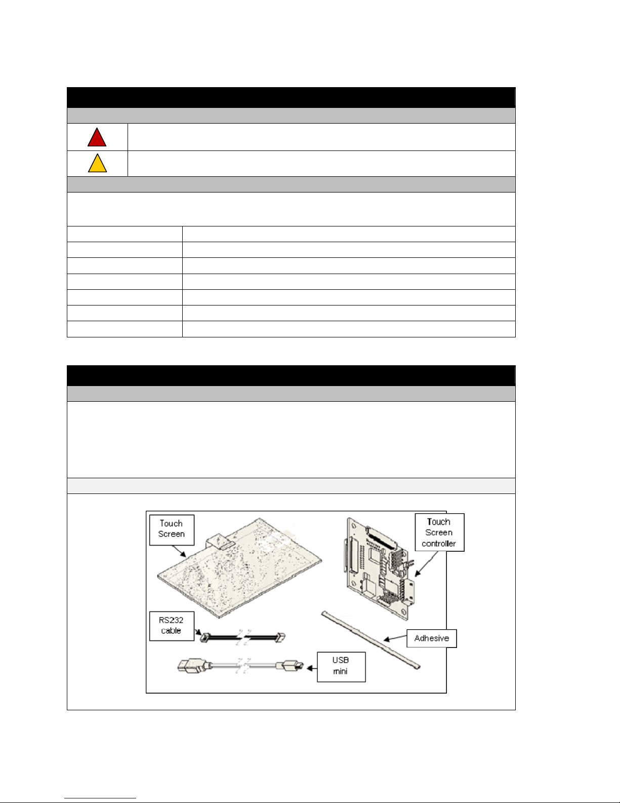
2.0 Touch Screen Kit
2.1 Components
Touch Screen
Touch Screen Controller
USB Mini Cable and/or RS232 Communication Cable and Power Cable
Adhesives
Figure 1: MulTI-Touch Screen Kit Components
Document Number: 6500493 Rev. 1.1 Pg. 4

3.0 Touch Screen Maintenance
3.1 Cleaning the Touch Screen
Caution: Do not use any cleaners with chemicals that can corrode glass or damage the touch
screen permanently. When cleaning the touch screen, use a soft, lint free cloth to prevent
scratches and contamination. Avoid using sharp/hard objects.
Before integrating the touch screen, make certain it is properly cleaned. It is highly recommended that the
installation of the touch screen is performed in a clean room to prevent any contamination.
1. Wear powder free gloves before handling the touch screen.
2. Wear a grounded wrist band to prevent any static damage to electronic components.
3. Clean both sides of the touch screen with a non-abrasive anti-static solution (lens cleaner).
4. Clean both sides of the touch screen again with rubbing alcohol.
5. Repeat steps 3 and 4 as needed until the touch screen is free of all contaminants, such as
fingerprints or dust.
6. Allow the touch screen to fully dry before integrating.
4.0 Touch Screen Integration
1.1 Integrating the Touch Screen
Caution: Practice safety while integrating touch screens, controllers, LCDs and all other
components included in this document. Beware of sharp edges which can cut or harm people.
MulTI-Touch touch screens can be integrated in a variety of ways. The most general method of integrating
the Touch Screen with a display is presented in Figure 2.
Figure 2: Touch Screen and Controller Inte g rat i o n
Document Number: 6500493 Rev. 1.1 Pg. 5

4.0 Touch Screen Integration (Continued)
4.2 Mounting the Touch Screen
The Projected Capacitive Touch Screen should be mounted to a display with an adhesive that is at least
.062” thick. To mount a bezel onto the Touch Screen, an adhesive that is at least .062” thick should also be
used.
The recommended adhesive is 3M 4956 VHB Tape. This adhesive can be provided by TI as P/N 1600136.
Please refer to Figures 2 and 3, which illustrate the mounting process.
Figure 3: Touch Screen Mounting
4.3 Touch Screen Placement and Alignment
When choosing a MulTI-Touch touch screen, ensure that its active area will fit with the activ e area of your
display. The active area of the sensor is enclosed by the edge sensor leads. Please see Figure 4 for more
details.
Carefully align the active area of the touch screen to the active area of the display. To ensure accurate
performance, the center X and Y points of the two active areas should be as close as possible to one
another. Typical integrations align the centers within ± .5 mm in both the X and Y positions. The better the
alignment, the more accurate the touch will be. Please refer to Figure 5, which illustrates the alignment.
Figure 4: Active Area Definition
Document Number: 6500493 Rev. 1.1 Pg. 6

4.0 Touch Screen Integration (Continued)
4.3 Touch Screen Placement and Alignment
Figure 5: Aligning Active Areas When Mounting
4.4 Bezel and Gasket Restritions
A single perimeter sealing gasket is recommended to ensure a complete seal. Otherwise, liquids or other
contaminants may enter the product.
When desired, gasket strips may also be used.
Bezels and gaskets should not be placed or mounted within the viewing area of the touch screen by
more than 0.020 inches (0.5 mm). Doing so may adversely affect the performance of the touch screen.
Non-conductive and non-porous gaskets should be used.
4.5 Electro-Magnetic Interference (EMI)
The touch screen and controller should be mounted away from components that create electro-magnetic or
radio frequency interference. Refrain from mounting the controller near devices that generate signals in
the range of 50 kHz to 100 kHz, as well as transformers and backlight inverters. Mounting near these
devices can interfere with the performance of the touch screen and controller.
If a plastic bezel is utilized, metalizing and grounding the bezel will help minimize EMI and noise. If a
metal bezel is employed, make sure it is properly grounded.
To shield components from the EMI generated by the touch screen and controller, cover the outer edges of
the touch screen and its tails with copper tape. Ensure that the copper tape does not lie within the viewing
or active area of the touch screen when covering the sen sor ’s edg es. Th e con troller should b e covere d with
three layers of tape. First, Kapton tape, then copper tape, then Kapton tape again. All copper tape needs to
be properly grounded.
Document Number: 6500493 Rev. 1.1 Pg. 7

4.0 Touch Screen Integration (Continued)
4.5 Underlay
A graphic underlay may be placed between the display and the touch screen. This underlay may be useful
in defining keys or buttons for special applications. An example is shown in Figure 6.
Figure 6: Graphic Underlay Example
5.0 Controller Integration
5.1 Mounting the Controller
Caution:
The controller is ESD sensitive. Please wear a grounded wrist strap while handling the
controller.
Make sure that the controller is grounded to the display’s casing or housing.
Mount the controller as far as possible from components that produce signals from 50 kHz to
100 kHz, as well as transformers and backlight inverters.
Nothing should contact the top and bottom sides of the controller; o therwise the controller may
short out.
The controller can be mounted in two ways. (See figures 7 and 8 for further information.)
1. Stand-offs with at least one grounded to the casing or housing.
2. Wire / cable grounded to the casing or housing
Document Number: 6500493 Rev. 1.1 Pg. 8

5.0 Controller Integration (Continued)
5.1 Mounting the Controller
Figure 7: Grounded Stand-Off Figure 8: Grounded Cable
If height restrictions cannot accommodate the use of standoffs, thin gaskets may be used to mount the
controller, as long as the controller is properly grounded with a cable. Please refer to Figure 9 for this set
up.
Figure 9: Gasket Mounting with Grounded Cable
Document Number: 6500493 Rev. 1.1 Pg. 9

6.0 Touch Screen Tails
6.1 Tail Guidelines
Keep touch screen tails away from components that create signals from 50kHz to 100kHz, as well as
transformers and backlight inverters.
Keep touch screen tails away from conductive materials if possible. Otherwise, the touch screen tails, or
the conductive surfaces should be shielded and separated from one another by at least 0.1”.
Shielding can be applied by placing Kapton or copper tape on the touch screen tails.
The touch screen tails should not bend at a radius less than 0.125”, as seen in Figure 10.
If the sensor tail runs through slots or around sharp edges, cushion the sharp edges to prevent damage to
the sensor tails. Please refer to Figure 11.
Figure 10: Touch Screen Tail Minimum Bend Radius
Figure 11: Cushion Edges Around the Touch Screen Tails
Document Number: 6500493 Rev. 1.1 Pg. 10

6.0 Touch Screen Tails (Continued)
6.1 Connecting the Tails to the Controller
1. To connect the Projected Capacitive Touch Screen tails to the controller, first pull out the connector
clips on the control board, as indicated by the red arrows in Figure 12(a). After the clips have been
pulled out, insert the sensor tails with the exposed copper wiring on top, as indicated by the blue arrows.
2. Once the sensor tails have been fully inserted into the connectors, close the connector clips to secure the
sensor tails in place. Figure 12(b) illustrates this step.
Figure 12(a): Step 1
Figure 12(b): Step 2
Document Number: 6500493 Rev. 1.1 Pg. 11
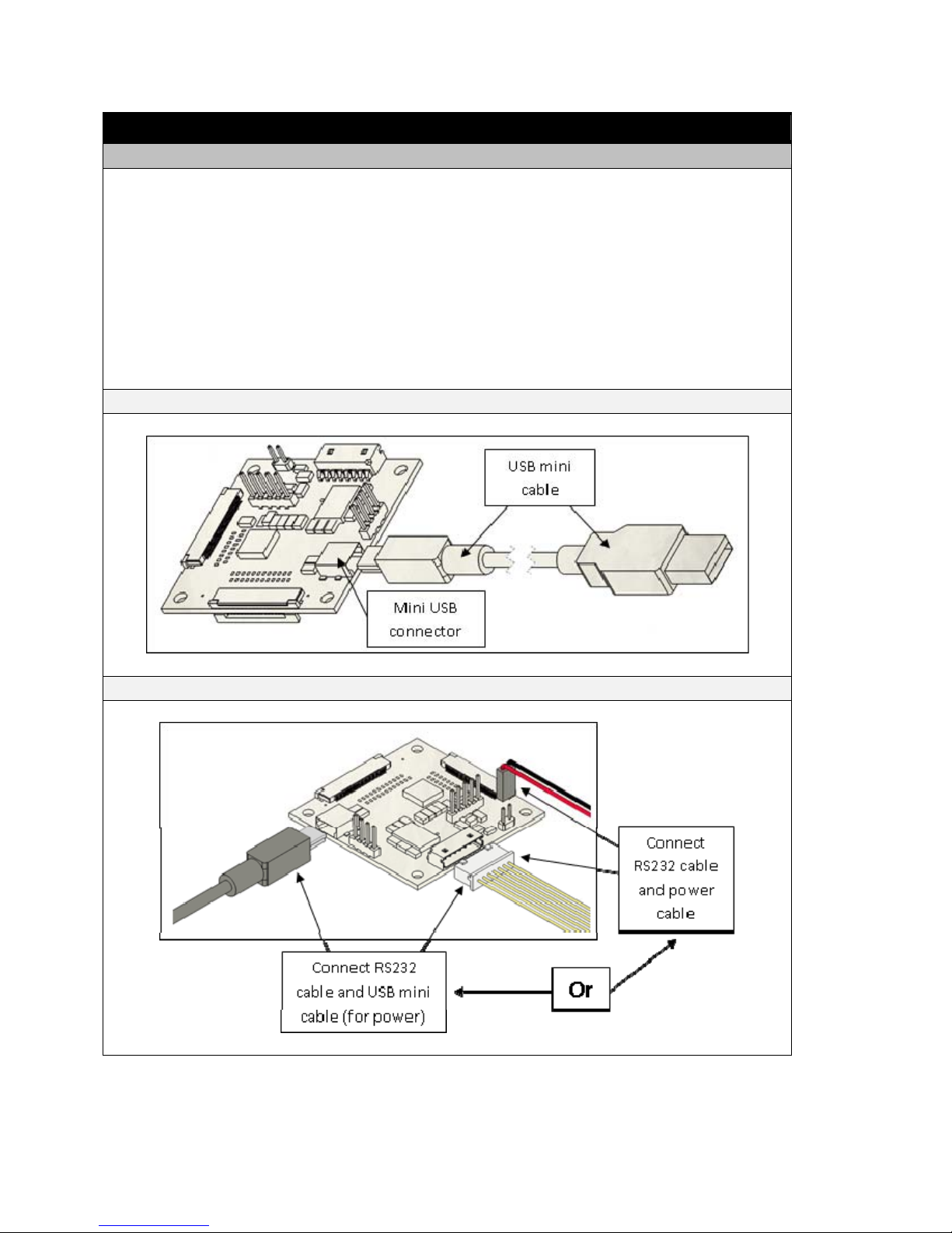
7.0 Communication
7.1 Controller/Cable Connections
Projected Capacitive controller boards can use different communication cables. The common setu ps are
detailed in this section. After attaching the appropriate cables, they should be secured or mounted to
ensure steady power supply and data communication for the control board.
1. A Projected Capacitive controller can use a USB mini cable to both power the board and provide data
communication. This is illustrated in Figure 14(a).
2. A Projected Capacitive controller can use a RS232 cable for data communication and a USB mini cable
to power the board. Another option is to use the RS232 cable for data communication and a power
cable. These different options are shown in Figure 14(b).
Figure 14(a): Connecting the USB Mini Cable
Figure 14(b): Connecting the RS232 Cable and Power
Document Number: 6500493 Rev. 1.1 Pg. 12
8.0 Troubleshooting
8.1 Checking All Connections
Make sure that the power cables and the communication cables are connected properly and firmly. Make
sure that the sensor tails are firmly attached to the controller.
When the controller is connected through a USB port for the first time, windows will automatically in stall
the driver for the controller.
8.2 Mounting the Touch Screen
Make sure to consider the following points while mounting the touch screen.
The touch screen is securely mounted on the LCD and the tails are securely connected to the controller.
The controller is firmly attached to the chassis and is grounded.
The tail of the Touch Screen is connected in such a way that it is not touching any metal objects.
Otherwise, utilize insulators between the tail and any metal objects it may contact. This will help reduce
the noise level.
8.3 Interference
Projected Capacitive sensors and controllers can be influenced by EMI and RFI. Make sure that the
controller is placed far from devices such as transformers and inverters. EMI and RFI can severely affect
the performance of the touch screen. Grounding the controller will help reduce EMI and RFI.
9.0 Maintaining the Touch Screen
Caution: Do not use any cleaners with chemicals that can corrode glass or damage the touch
screen permanently. When cleaning the touch screen, use a soft, lint free cloth to prevent
scratches and contamination. Avoid using sharp/hard objects.
Always wear a grounded wrist strap while handling the touch screen and controller.
For high visual clarity, clean the touch screen periodically to remove fingerprints and foreign objects.
Do not press the touch screen with extreme force.
Avoid the use of sharp / hard objects on the touch screen.
Keep sensor tails away from sharp objects and handle them with care.
Technical Support
If you require additional assistance, please contact our technical support team at support@touchintl.com.
Document Number: 6500493 Rev. 1.1 Pg. 13
 Loading...