

Page 1
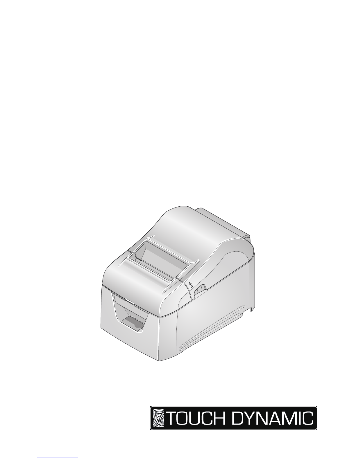
Hardware Manual
THERMAL PRINTER
TP4000
Page 2

Notice
• All rights reserved. Reproduction of any part of this manual in any form whatsoever, without TP4000’s express
permission is forbidden.
• The contents of this manual are subject to change without notice.
• All efforts have been made to ensure the accuracy of the contents of this manual at the time of going to press.
However, should any errors be detected, TP4000 would greatly appreciate being informed of them.
• The above notwithstanding, TP4000 can assume no responsibility for any errors in this manual.
Copyright © Touch Dynamic TP4000
Federal Communications Commission
Radio Frequency Interference
Statement
This device complies with Part 15 of the FCC Rules. Operation is subject to the following two conditions: (1) This
device may not cause harmful interference, and (2) this device must accept any interference received, including
interference that may cause undesired operation.
NOTE: This equipment has been tested and found to comply with the limits for a Class A digital device,
pursuant to Part 15 of the FCC Rules. These limits are designed to provide reasonable protection against harmful
interference when the equipment is operated in a commercial environment. This equipment generates, uses and can
radiate radio frequency energy and, if not installed and used in accordance with the instruction manual, may cause
harmful interference to radio communications. Operation of this equipment in a residential area is likely to cause
harmful interference in which case the user will be required to correct the interference at his own expense.
This statement will be applied only for the equipments marketed in U.S.A.
FCC WARNING
Changes or modications not expressly approved by the party responsible for compliance could void the user’s
authority to operate the equipment.
For compliance with the Federal Noise Interference Standard, this equipment requires a shielded cable.
For RF interference suppression, if a ferrite core is provided with this device, afx it to the interface cable.
Statement of
The Canadian Department of Communications
Radio Interference Regulations
This Class A digital apparatus complies with Canadian ICES-003.
Cet appareil numérique de la classe A est conforme à la norme NMB-003 du Canada.
The above statement applies only to equipments marketed in Canada.
Warning:
This is a class A product. In a domestic environment this product may cause radio interference in which case the
user may be required to take adequate measures.
Trademark acknowledgments
TP4000: Touch Dynamic TP4000
Page 3

TABLE OF CONTENTS
1. Unpacking and Installation ...................................................................................1
1-1. Unpacking .......................................................................................................................1
1-2. Notes about Installation ..................................................................................................1
2. Parts Identication and Nomenclature ................................................................2
3. Setup ........................................................................................................................3
3-1. Connecting the Interface Cable to the PC ......................................................................3
3-2. Connecting the Interface Cable to the Printer ................................................................4
3-3. Connecting the AC Adapter ............................................................................................6
3-4. Turning the Power On ....................................................................................................7
3-5. Connecting to a Peripheral Device .................................................................................7
3-6. Loading a Paper Roll ......................................................................................................8
3-7. Changing the Paper Width ............................................................................................10
3-8. Setup Precautions .........................................................................................................11
4. Attaching the Accessories ....................................................................................13
4-1. Attaching the Holder Plate ...........................................................................................13
5. Troubleshooting ....................................................................................................15
5-1. Error Indicators .............................................................................................................15
6. Preventing and Removing Paper Jams ..............................................................16
6-1. Preventing Paper Jams ..................................................................................................16
6-2. Removing Paper Jams ..................................................................................................16
6-3. Releasing the Cutter Lock ............................................................................................17
7. Maintenance .........................................................................................................18
7-1. Thermal Head ...............................................................................................................18
7-2. Platen Rubber Roller ....................................................................................................18
7-3. Paper Holder .................................................................................................................18
7-4. Sensors and Their Surrounding Area ............................................................................18
Page 4
-
1
-
1. Unpacking and Installation
1-1. Unpacking
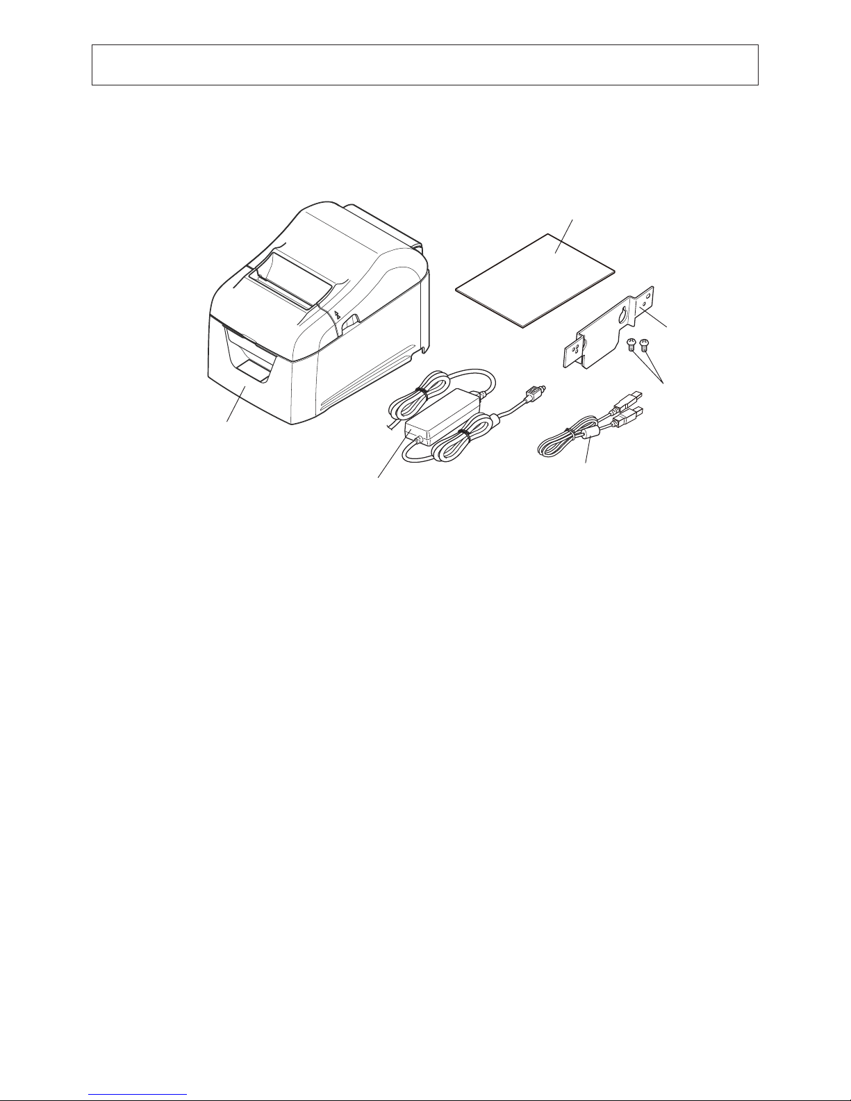
After unpacking the unit, check that all the necessary accessories are included in the package.
1-2. Notes about Installation
1. Choose a rm, level surface where the printer will not be exposed to vibration.
2. The power outlet you plan to connect to for power should be nearby and unobstructed.
3. Make sure that the printer is close enough to your host computer for you to connect the two.
4. Make sure that the printer is not exposed to direct sunlight.
5. Make sure that the printer is well away from heaters and other sources of extreme heat.
6. Make sure that the surrounding area is clean, dry, and free of dust.
7. Make sure that the printer is connected to a reliable power outlet. It should not be on the same electric circuit as copiers,
refrigerators, or other appliances that cause power spikes.
8. Make sure that the room where you are using the printer is not too humid.
9. Use the printer within the boundaries indicated in the environmental requirements. Even when the ambient temperature
and humidity are within the specications, avoid radical changes in environmental conditions. The suitable operating
temperature range is as follows:
Operating temperature: 5°C to 45°C
10. When disposing of the printer, obey local regulations.
Printer
Safety Instructions
Power Unit
USB Cable
Two Screws
Holding Plate
Page 5
-
2
-
2. Parts Identication and Nomenclature
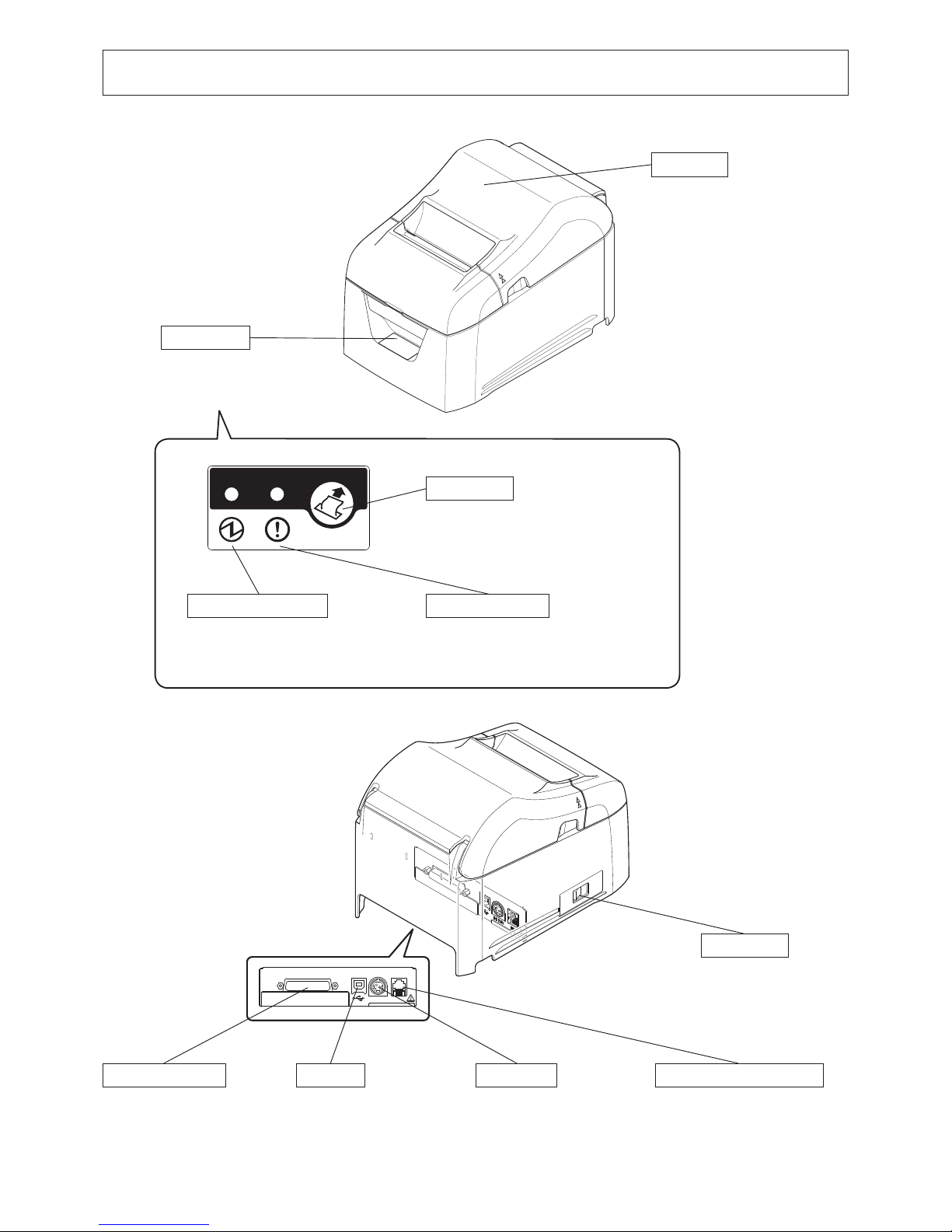
Control panel
Features lamps that indicate
printer status and a button for
operating the printer.
Rear cover
Open to replace paper.
Do not open while printing.
DC24V DK
Power switch
Turns the printer on
and off.
Connects to peripheral devices
such as cash drawers.
Do not connect this to a telephone
line.
Peripheral drive connector
Connects to an AC
adapter.
Power inlet
Connects to a host PC
through a USB cable.
USB port
Connects to a host PC
through a cable.
Interface connector
Lights when the printer is online.
This lamp also indicates errors, in
combination with other lamps.
Lights when the cover is open.
This lamp also indicates errors, in
combination with other lamps.
When the printer is online, pressing
this button feeds the paper roll.
POWER lamp (green) ERROR lamp (red)
FEED button
Page 6
-
3
-
3. Setup
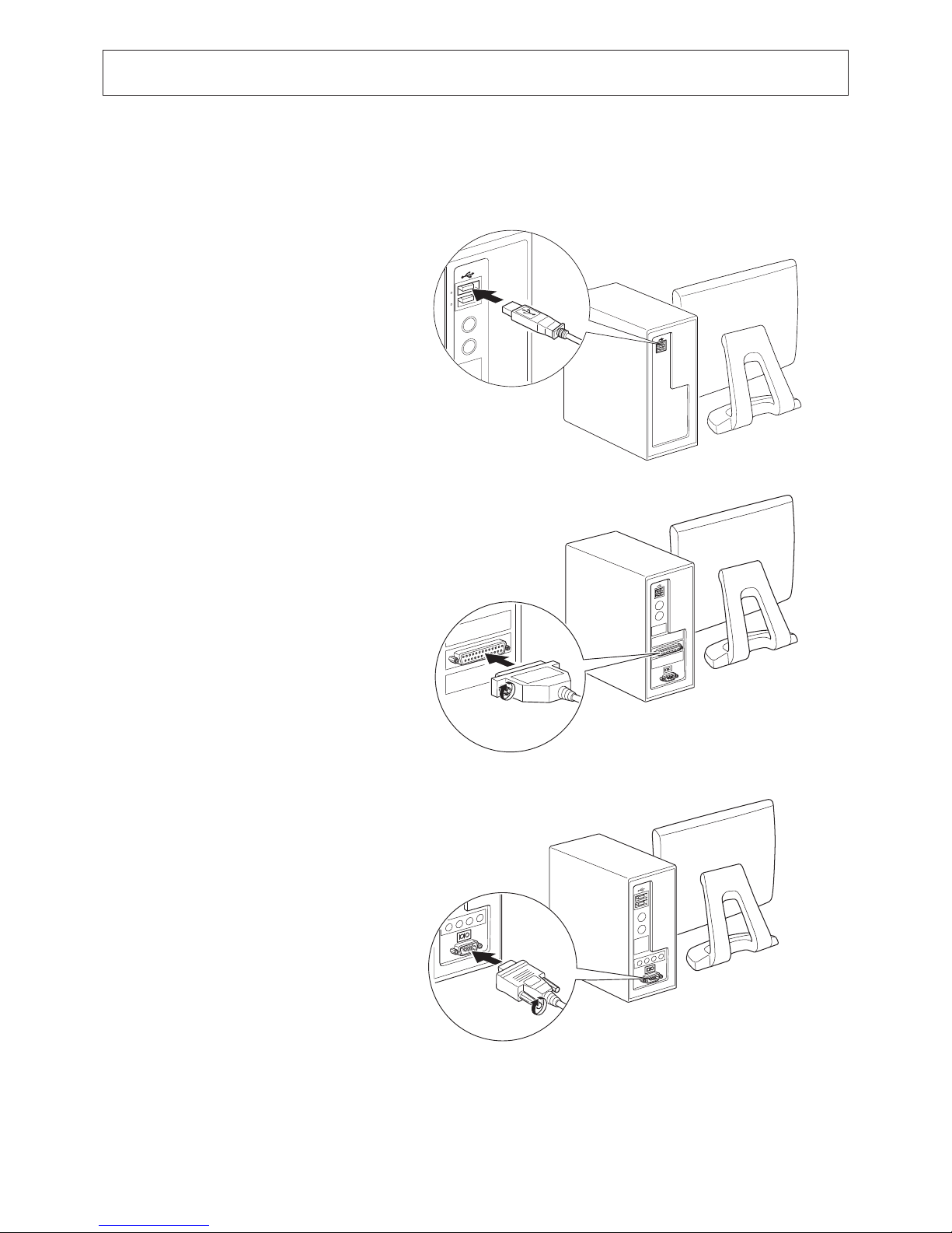
3-1. Connecting the Interface Cable to the PC
3-1-1. USB Cable
Connect the USB cable to a USB port on your PC.
3-1-2. Parallel Cable
Connect the parallel cable to a parallel port on your PC.
3-1-3. RS-232C Cable
Connect the RS-232C cable to a RS-232C port on your PC.
Page 7
-
4
-
3-2. Connecting the Interface Cable to the Printer
Obtain an appropriate cable that complies with the specications beforehand.
Because the appropriate interface cable differs depending on the system that you are connecting the printer to, contact the dealer
that you bought the product from if you are unsure about what cable to use.
Before connecting or disconnecting an interface cable, be sure to disconnect the AC adapter’s power cord from the outlet.
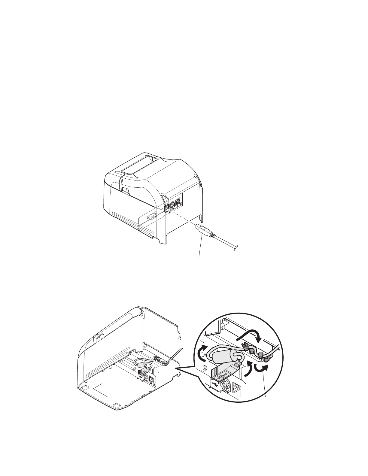
3-2-1. USB Cable
To connect a USB cable, follow the procedure given below.
1) Make sure that the AC adapter’s power cord is not connected to the outlet.
2) Connect the USB cable to the USB port.
3) As shown in the gure, pass the cable through the cable hooks to hold it in place.
Cable hook
USB cable
Page 8
-
5
-
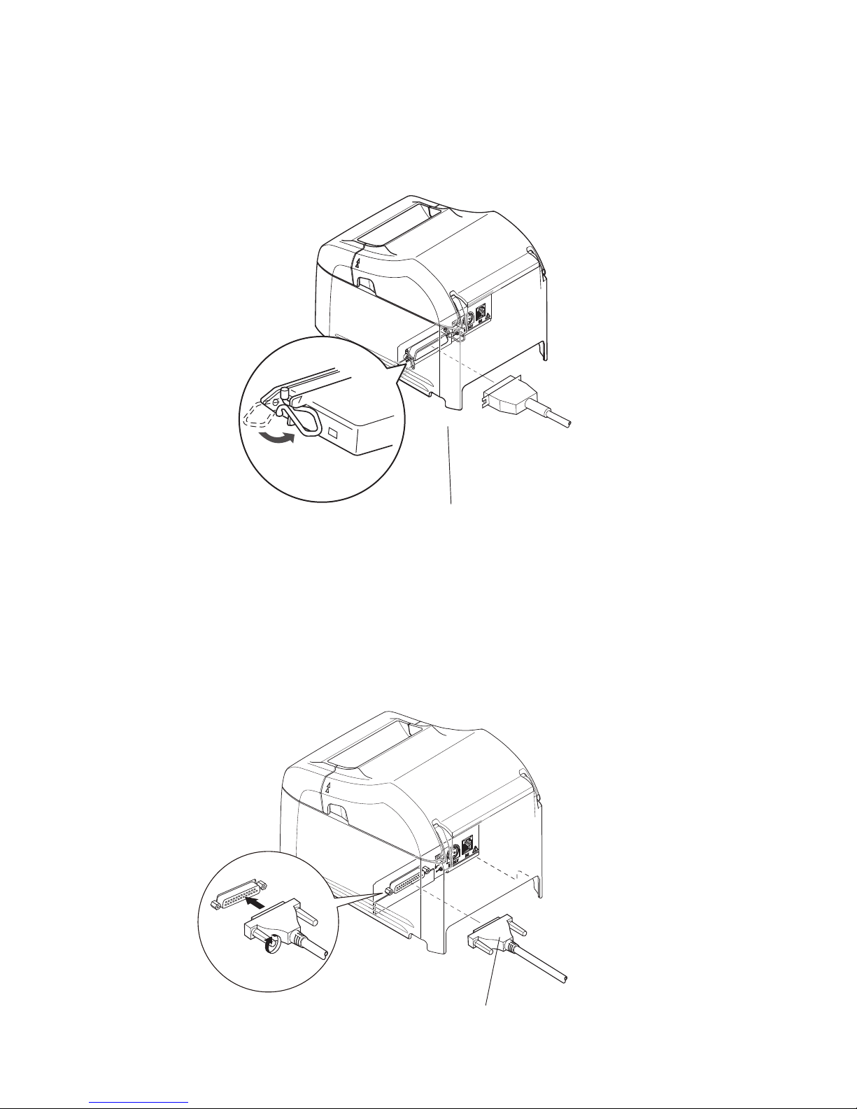
3-2-3. RS-232C Cable
To connect an RS-232C cable, follow the procedure given below.
1) Make sure that the AC adapter’s power cord is not connected to the outlet.
2) Connect the RS-232C cable to the connector on the RS-232C interface board, and tighten the left and right screws.
3-2-2. Parallel Cable
To connect a parallel cable, follow the procedure given below.
1) Make sure that the AC adapter’s power cord is not connected to the outlet.
2) Connect the parallel cable to the connector on the parallel interface board, and fasten the connector clasps.
RS-232C cable
Parallel cable
Page 9
-
6
-
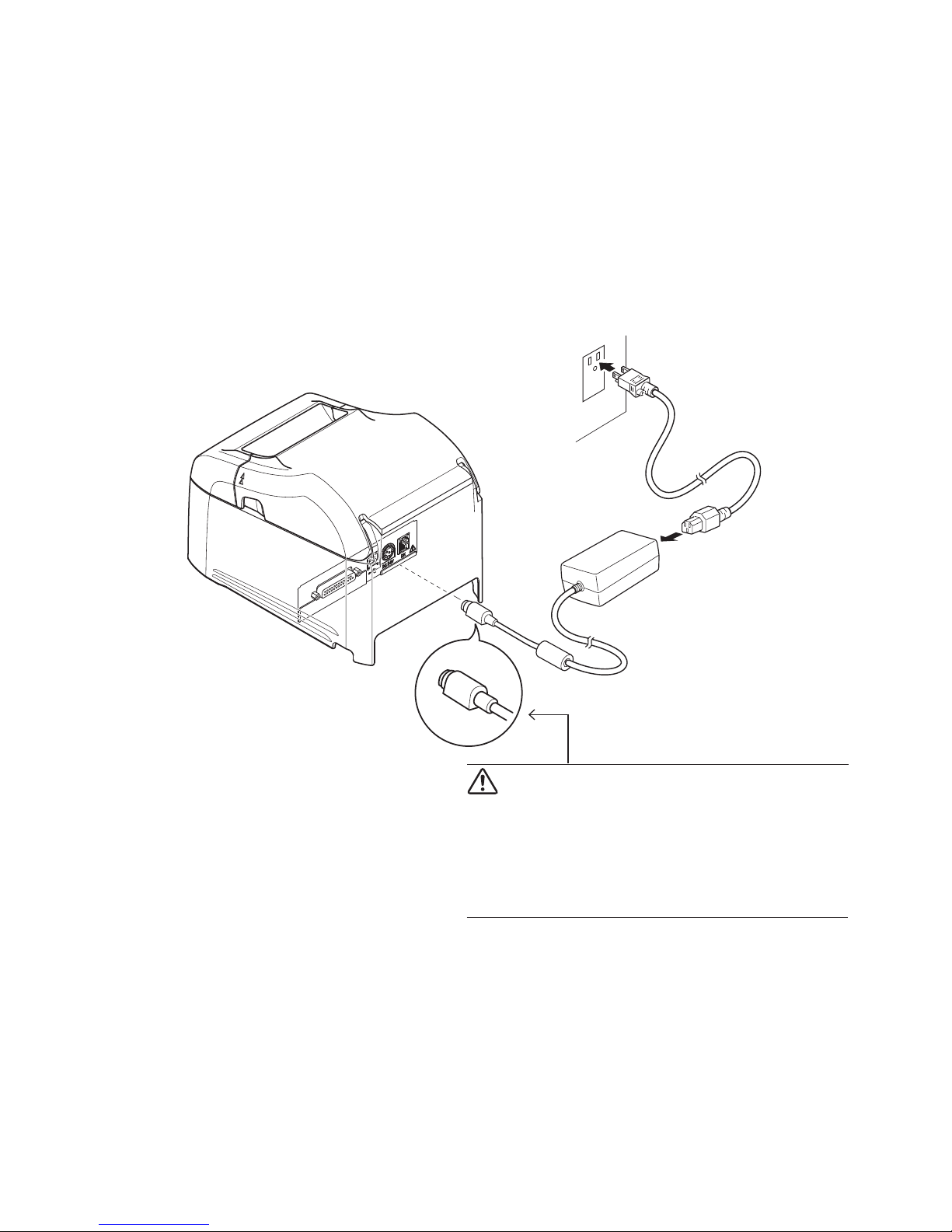
3-3. Connecting the AC Adapter
Note: Before connecting or disconnecting the AC adapter, make sure that the printer and all the devices connected to it
are turned off.
Then remove the power cord from the outlet.
1) Connect the AC adapter to the power cord.
2) Connect the AC adapter to the connector on the printer.
3) Insert the power cable plug into an AC outlet.
CAUTION
When disconnecting the cable, take hold of the cable
connector to pull it out. Releasing the lock makes it
easy to disconnect the connector.
Pulling the cable excessively could cause damage to
the connector.
Page 10
-
7
-
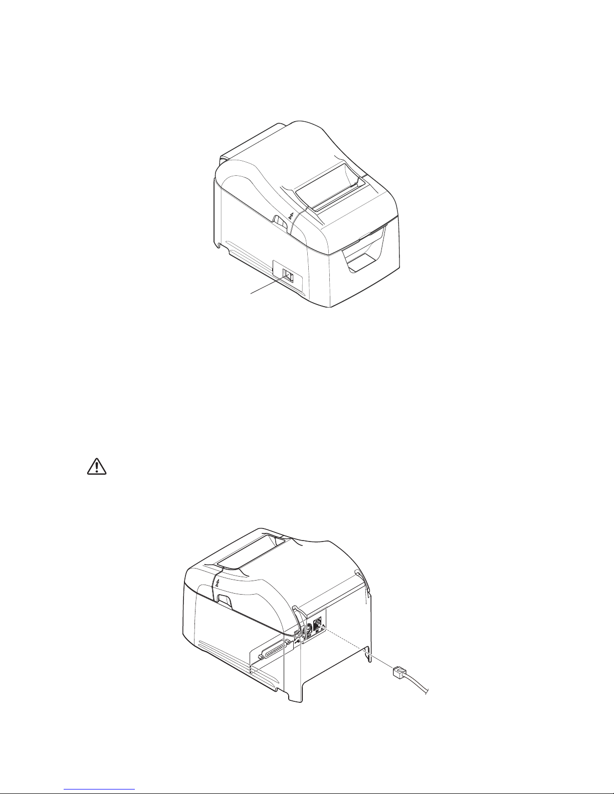
3-4. Turning the Power On
Connect the power cord according to the procedure in section 3-3, “Connecting the AC Adapter”.
Turn on the power switch, which is on the left side of the printer.
The POWER lamp on the control panel will light.
3-5. Connecting to a Peripheral Device
You can connect a peripheral device to the printer using a modular plug.
Follow the procedure given below.
1) Make sure that the AC adapter’s power cord is not connected to the outlet.
2) Connect the modular jack plug to the peripheral drive connector on the rear panel of the printer.
Connect the other end of the cable to the modular jack of the peripheral device.
CAUTION: Do not connect a telephone line to the peripheral drive connector. Doing so may cause the printer
to malfunction. Also, for safety purposes, do not connect a wire that may carry excessive voltage
to the peripheral drive connector.
Power switch
Page 11
-
8
-
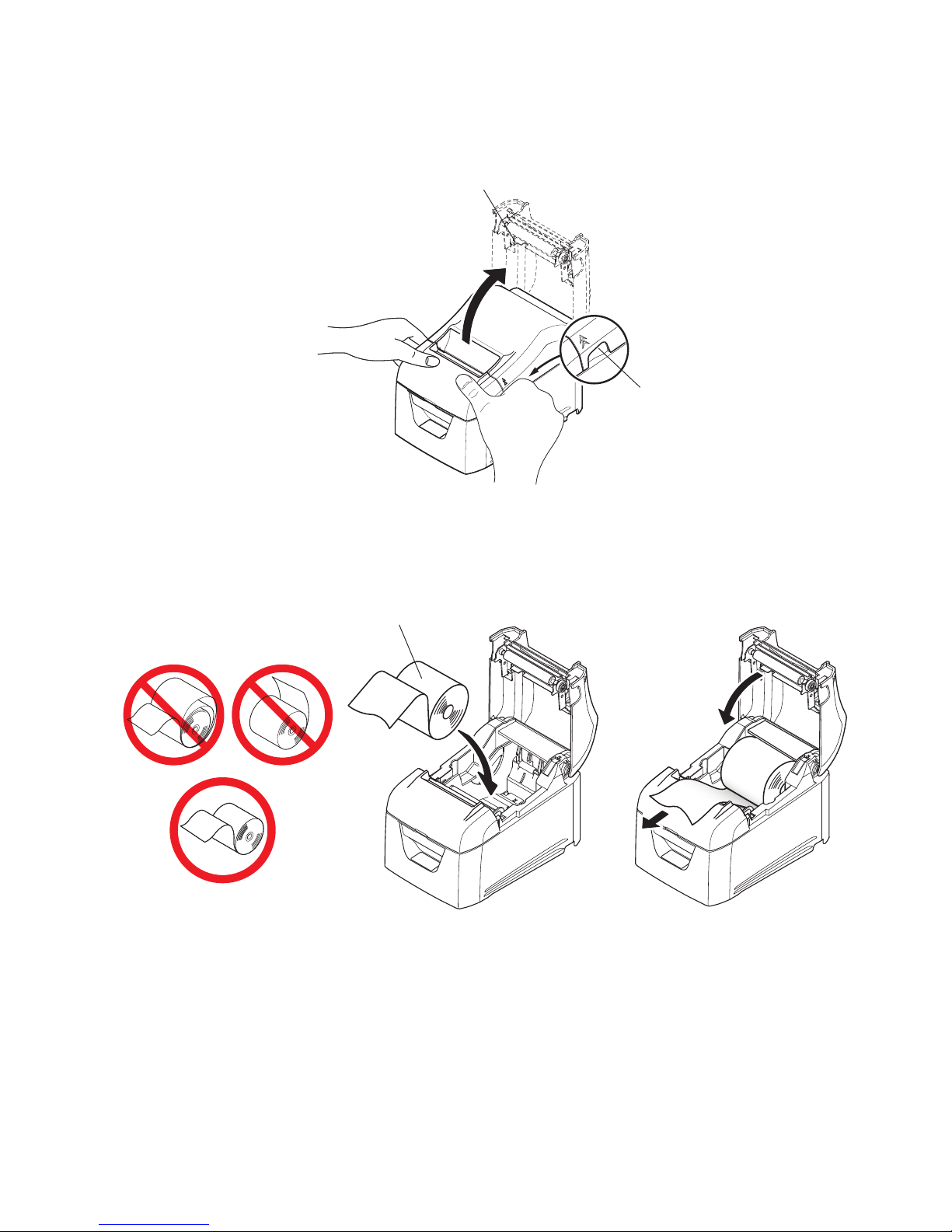
3-6. Loading a Paper Roll
Use a paper roll that complies with the printer specications. (See section 3-6-1, “Compliant Paper Roll Specications”.)
1) Put your ngers in the grooves on either side of the printer, and open the rear cover.
3) Push on both sides of the rear cover to close it.
Note 1: Be sure not to close the rear cover by pushing only one side.
2: Be careful not to get your ngers caught when opening or closing the printer’s rear cover.
3: After the rear cover is closed, the printer performs initial operations (from paper feeding to paper cutting).
Do not open the rear cover until the initial operations are complete.
2) Load the paper roll into the printer in the direction indicated by the gure, and pull the leading edge of the paper straight
toward you.
Note 1: Pull the paper straight as you pull it out.
2: Be careful not to pull the paper out at an angle, because doing so may cause the paper to jam or skew.
Paper roll
Groove
Rear cover
Page 12
-
9
-
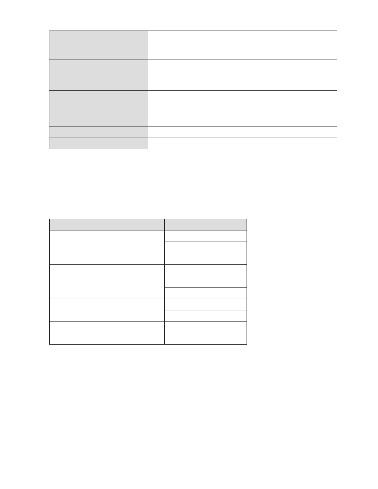
3-6-1. Compliant Paper Roll Specications
Paper thickness
65 μm to 85 μm
Note: For paper thinner than 65 μm, we recommend settings for only Mitsubishi Hitec
F5041 , Nippon Paper Industries TF50KS-E2D and KSP P30023/P31023.
Paper width
79.5
± 0.5
mm
57.5
± 0.5
mm
Note: Never change the paper width while the printer is in use.
External dimensions
• Roll diameter
Max. 80 mm
• Take up paper roll width
80
+0.5
mm / 5
8
+0.5
mm
Core inner and outer diameters
Inner diameter 12 ± 1 mm, external diameter 18 ± 1 mm
Printed surface
Outer edge of roll * You cannot use inner-wrapped paper rolls.
Note 1: Do not glue or tape the paper roll and shaft core together.
2: Do not fold the tail end of the paper.
3-6-2. Recommended Paper Roll
Manufacturer Product name
Mitsubishi Paper Mills Limited P220AG
HP220A
HP220AGB-1
Mitsubishi HiTec Paper Flensburg GmbH F5041
Oji Paper Co., Ltd. PD150R
PD160R
Nippon Paper Industries
TF50KS-E2D
TF60KS-E
KSP P30023
P31023
Note : Depending on the type and thickness of the paper, it may be necessary to change the settings for printing
darkness.
- 1
- 1
Page 13
-
10
-
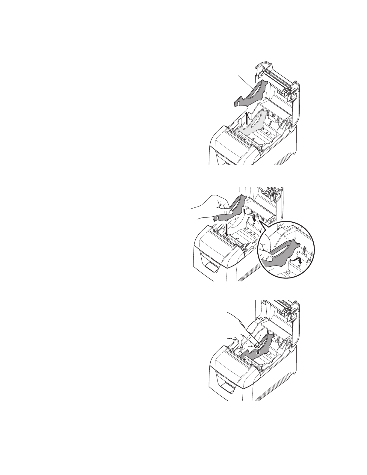
3-7. Changing the Paper Width
Move the paper roll guide to match the paper roll width. When you change the effective print width (paper roll width), change
the printer utility’s memory switch setting. For details, see the printer utility help.
* The following procedure is for changing the paper width from 79.5 mm to 57.5 mm.
1) Remove the paper roll guide.
2) As shown in the gure, insert the paper roll guide in the groove.
3) Secure the paper roll guide in place by pushing the section marked as “A” in the gure.
Note: Do not change the paper width while the printer is in use.
The amount of wear on the thermal head, rubber roller, and cutter varies depending on the paper width. This
varying amount of wear may cause problems in printing and cutting.
A
Paper roll guide
Page 14
-
11
-
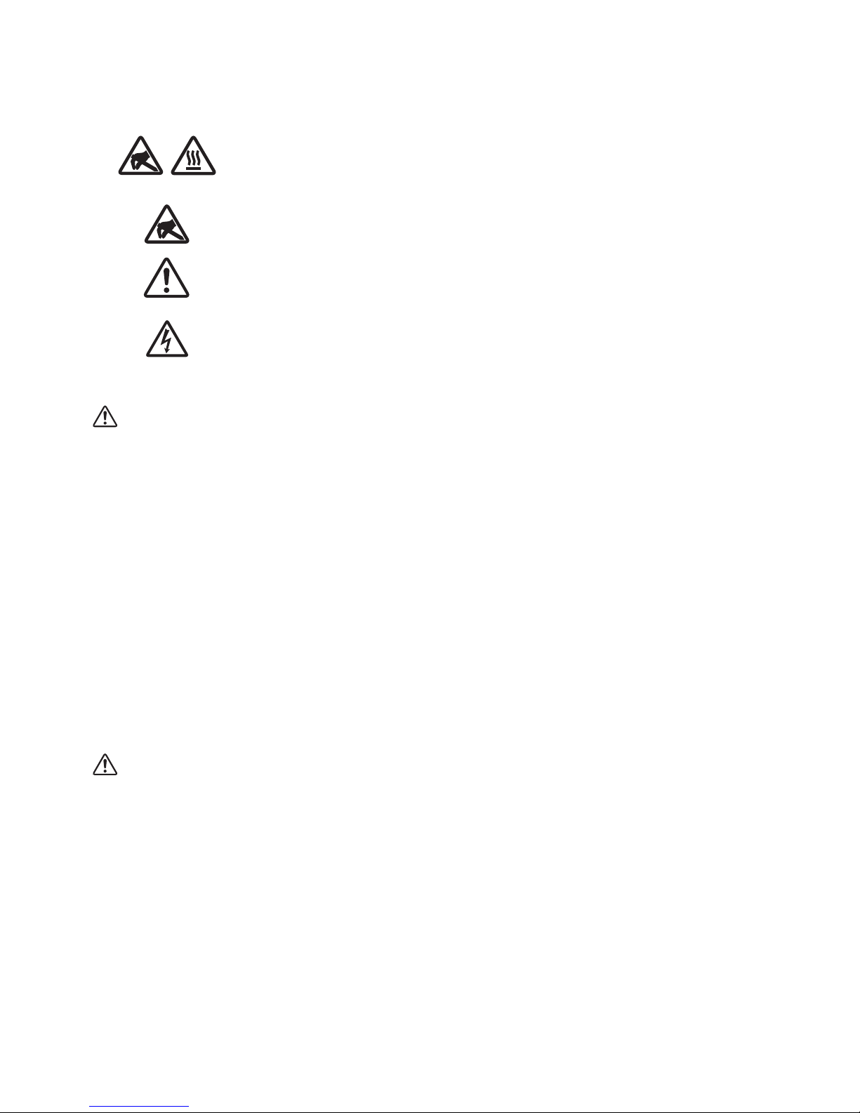
Caution Symbol
These symbols are located near the thermal print head.
Because the thermal print head is hot immediately after printing, do not touch it. Static electricity
can damage the thermal print head. To protect the thermal print head from static electricity, do
not touch it.
This symbol is located near the cutter.
Never touch the cutter blade, as you could injure your ngers.
This symbol is located near the peripheral drive connector.
Do not connect this to a telephone.
This symbol is located near the screws securing the case or the protective plate, which should not
be opened by individuals other than service personnel. Individuals, other than service personnel,
should not remove these screws. High voltage areas in the case can be dangerous.
WARNING
If you notice smoke or strange odors coming from this product, turn the power switch off immediately, and remove the
power cord from the AC outlet. For repairs, contact the dealer that you bought the product from.
Never attempt to repair the product yourself. Doing so can be dangerous.
Never disassemble or modify the product. Doing so may result in injury, re, or electric shock.
On models that have cutters or tear bars, do not touch the cutter blade or the tear bar.
-
There is a cutter or tear bar inside the paper outlet slot. Never put your hand in the slot regardless of whether or not the
printer is in operation.
-
You must open the printer cover to replace paper. However, because the cutter blade or tear bar is located inside of the
cover, be careful not to bring your face and hands too close to the blade or tear bar when the cover is open.
During and immediately after printing, the area around the print head is very hot. Don’t touch it because you could be
burned.
Be sure to turn off the printer before performing maintenance on the cutter. Failing to do so is dangerous.
CAUTION
We recommend that you unplug the printer from the power outlet whenever you do not plan to use the printer for long
periods.
Because of this, you should locate the printer so that the power outlet it is plugged into is nearby and easy to access.
If an AC cord set is supplied with the product, the power cord that is included has been specially designed for the product.
Make sure that the printer and the PC are turned off and unplugged from their AC outlets before you make connections.
Do not connect a telephone line to the peripheral drive connector, which is used for devices such as cash drawers. Doing so
may cause the printer to malfunction. Also, for safety purposes, do not connect a wire that may carry excessive voltage to
the peripheral drive connector.
3-8. Setup Precautions
Page 15

-
12
-
Do not open the printer covers while the printer is printing or cutting.
Do not pull out paper when the printer cover is closed.
If liquid or foreign objects (such as coins and paper) enter the inside of the printer, turn the power switch off, disconnect
the power cord from the AC outlet, and consult the dealer that you bought the product from.
Continuing to use the printer may lead to a short-circuit, which may cause electric shock or re.
The heating element and the driver IC of the thermal print head are easily damaged. Do not touch them with metal objects,
sandpaper, etc.
Do not touch the thermal print head heating element. Doing so may make it dirty, which will decrease the printing quality.
Static electricity can damage the driver IC and other components of the thermal print head. Avoid touching it directly.
Do not operate the printer if there is moisture (which has been caused by condensation or another factor) on the front sur-
face of the head.
The printing quality and the thermal print head’s service life cannot be guaranteed if paper other than the recommended
paper is used.
In particular, thermal paper containing Na+, K+, or C1- may drastically reduce the service life of the thermal print head.
We recommend that you use paper with the following maximum ion densities: 500 ppm of Na+, 150 ppm of K+, and 300
ppm of Cl-.
Page 16
-
13
-
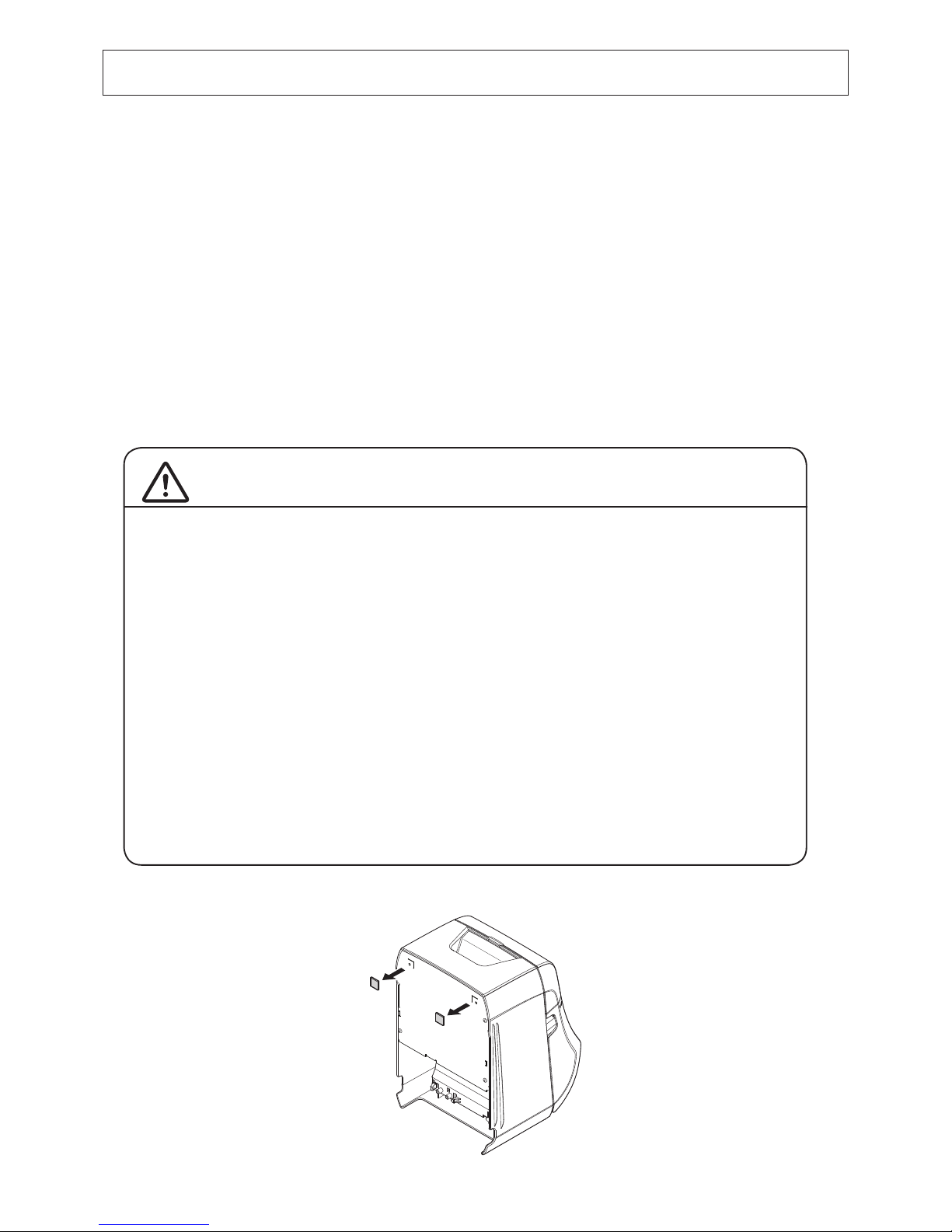
The following accessories are necessary when mounting the printer to a wall.
• Holding plate and two screws
4-1. Attaching the Holder Plate
■ The holder plate is attached to the printer using the included screws and is hooked onto screws that are
installed into the wall.
■ The screws on the wall are not included.
Use commercially available screws (4 mm diameter) that are suitable for the wall material (wood, steel
beam, concrete, etc.).
■ The printer’s weight is approximately 2.4 kg when the largest diameter roll paper is loaded.
Use screws on the wall that have both shear strength and pulling-out strength to withstand a force of at
least 12 kgf (118 N).
Precautions regarding installation
CAUTION
This caution indicates information that, if ignored, could lead to
personal injury or property damage.
• Be sure to have qualied personnel install the specied screws and printer to the wall.
Star is not responsible for any accidents or injuries that occur as a result of improper installation, misuse, or modications.
Especially when installing the printer at a high location, make sure that the printer is securely installed to the wall.
If the printer is not installed securely and falls, personal injury or damage to the printer
may result.
• Make sure that the mounting surface and installation screws are strong enough to install
the printer.
Securely install the printer so that the weight of the printer and any connected cables will
not cause the printer to fall.
Otherwise, personal injury or damage to the printer may result.
• Do not install the printer in an unstable location or a location that is exposed to vibration
and shocks.
If the printer falls, personal injury or damage to the printer may result.
(1) Remove the rubber feet from the printer unit.
4. Attaching the Accessories
Page 17
-
14
-
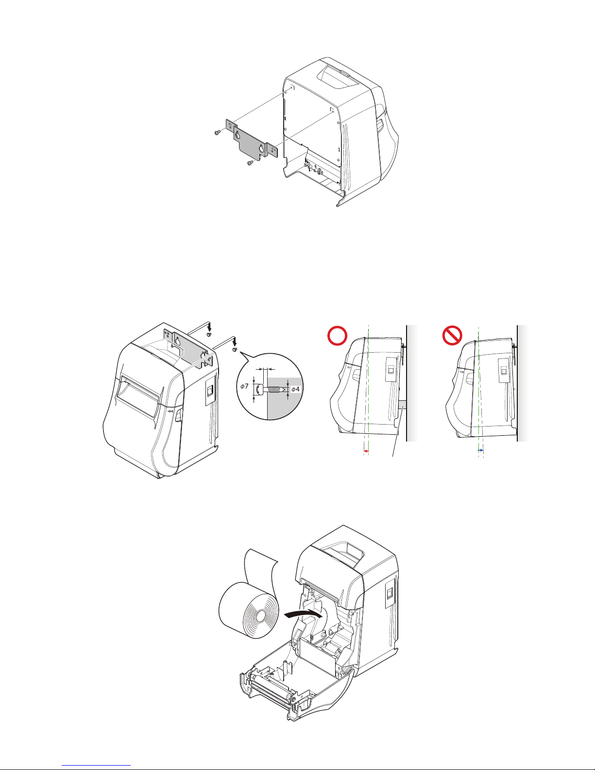
(2) Attach the holding plate to the printer. Then tighten the two screws that were supplied to secure it in place.
(3) Position the printer over the screws, etc., on the wall and then slide it downward to set it in place. After setting the printer
in place, check the screws on the wall again to make sure that they are able to support the printer’s weight.
(4) Open the printer cover.
(5) Insert the roll paper as shown.
Note 1: The printer’s weight is approximately 2.4 kg when the largest diameter roll paper is loaded. Use screws on
the wall that have both shear strength and pulling-out strength to withstand a force of at least 12 kgf (118
N).
2: When installing the printer on a wall, be sure the installation surface of the printer has an angle between
0 to +10 degrees with respect to the wall. If the installation angle of the printer with respect to the wall is
negative, paper near end may not be detected correctly.
0~+10°
2〜3mm
Rubber feet and the like
Page 18
-
15
-
5-1. Error Indicators
(1) Recoverable errors
Check the recovery conditions. The printer can be recovered while maintaining its current status.
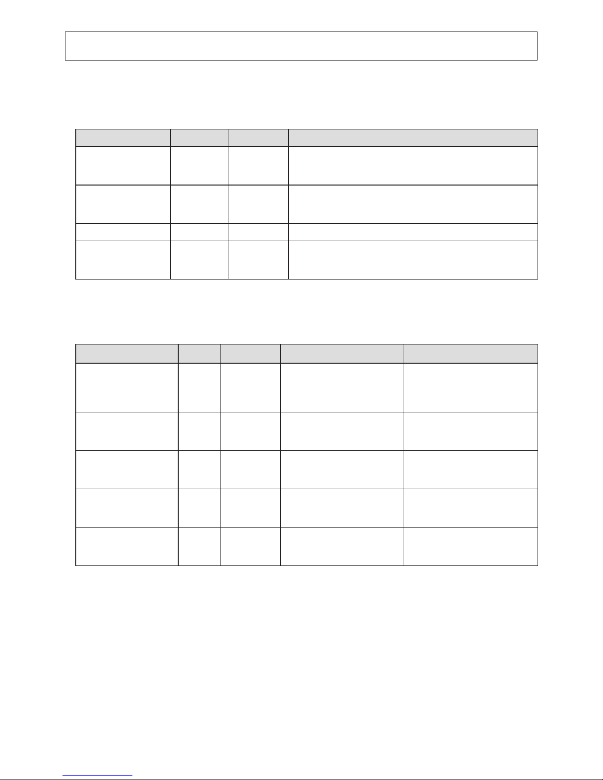
Error description POWER ERROR Recovery condition
Thermal head high
temperature detection
error
Flashes at
1-second
intervals
Off The printer recovers automatically when the thermal head cools.
Paper near end On
Flashes at
4-second
intervals
The printer recovers when you set a new paper roll and close the cover.
Cover open error On On The printer recovers when you close the cover.
Paper out error On
Flashes at
1-second
intervals
The printer recovers when you set a new paper roll and close the cover.
(2) Unrecoverable errors
Turn the printer off, check the recovery conditions, and then turn the printer back on.
If the same error occurs after you turn the printer back on, the printer needs to be repaired.
Error description POWER ERROR Cause Recovery condition
Cutter error Off
Flashes at
0.25-second
intervals
Paper cutting in progress error
After you restart the printer, the
printer recovers when the mobile
cutter returns to its home position.
(Note 3, 4)
Flash memory error Off
Flashes at
1-second
intervals
Flash memory access error -
RAM error Off
Flashes at
2-second
intervals
RAM access error -
Head thermistor error Off
Flashes at
3-second
intervals
Detection of head thermistor
error
-
Power voltage error Off
Flashes at
4-second
intervals
Detection of power voltage error
Check the condition of the power
supply, and restart the printer.
Note 1: If an unrecoverable error occurs, turn the power off immediately.
2: A power voltage error may be a result of a power supply malfunction.
3: If the paper is jammed, turn the power off, clear the jammed paper, and then turn the power back on.
For details, see section 6-2, “Removing Paper Jams”.
4: If the mobile cutter cannot return to its home position or the printer cannot perform initial operations,
manually unlock the cutter. For details, see section 6-3, “Releasing the Cutter Lock”.
If other unrecoverable errors occur, contact the dealer that you bought the product from for repairs.
5. Troubleshooting
Page 19
-
16
-
6. Preventing and Removing Paper Jams
6-1. Preventing Paper Jams
When you set the paper roll into the printer, do not pull out the end of the paper at an angle.
Do not touch the paper roll when the printer is printing or feeding paper or before the cut operation has nished completely.
Holding or pulling the paper while it is being fed may cause paper jams, improper cutting, or improper line breaks.
Note: Do not remove the paper while it is being cut. This can cause a paper jam.
6-2. Removing Paper Jams
If a paper jam occurs, remove the paper according to the procedure given below.
1) Turn the power switch off.
2) Open the rear cover.
Note 1: If you cannot open the rear cover, see section 6-3, “Releasing the
Cutter Lock”.
3) Remove the jammed paper.
Note 1: Because the thermal head is hot immediately after printing, do not
touch it.
2: Do not pull on the paper with the rear cover closed. Doing so may cause
damage to or deformation of parts such as the thermal head and the
rubber roller.
4) Load the paper roll straight, and gently close the rear cover.
Note 1: Load the paper roll straight.
If you close the rear cover with the paper roll skewed, paper jams may occur.
2: Push on both sides of the rear cover to close it securely.
Pushing the center section of the cover may cause only one side of the cover to be closed completely.
If the rear cover is not closed completely, the printer may not print.
5) Turn the power switch on.
Make sure that the ERROR lamp is not lit.
Note: When the ERROR lamp is lit, the printer will not accept any commands. Be sure to close the rear cover
completely.
CAUTION
To avoid paper jams and other problems, feed the paper at least 1 mm (8 dot lines) before printing.
If you want to use the cutter, to avoid paper jams and other problems, we recommend a margin of at least 5 mm
from the end of the printed area to the cutting position.
Thermal head
Page 20
-
17
-
6-3. Releasing the Cutter Lock
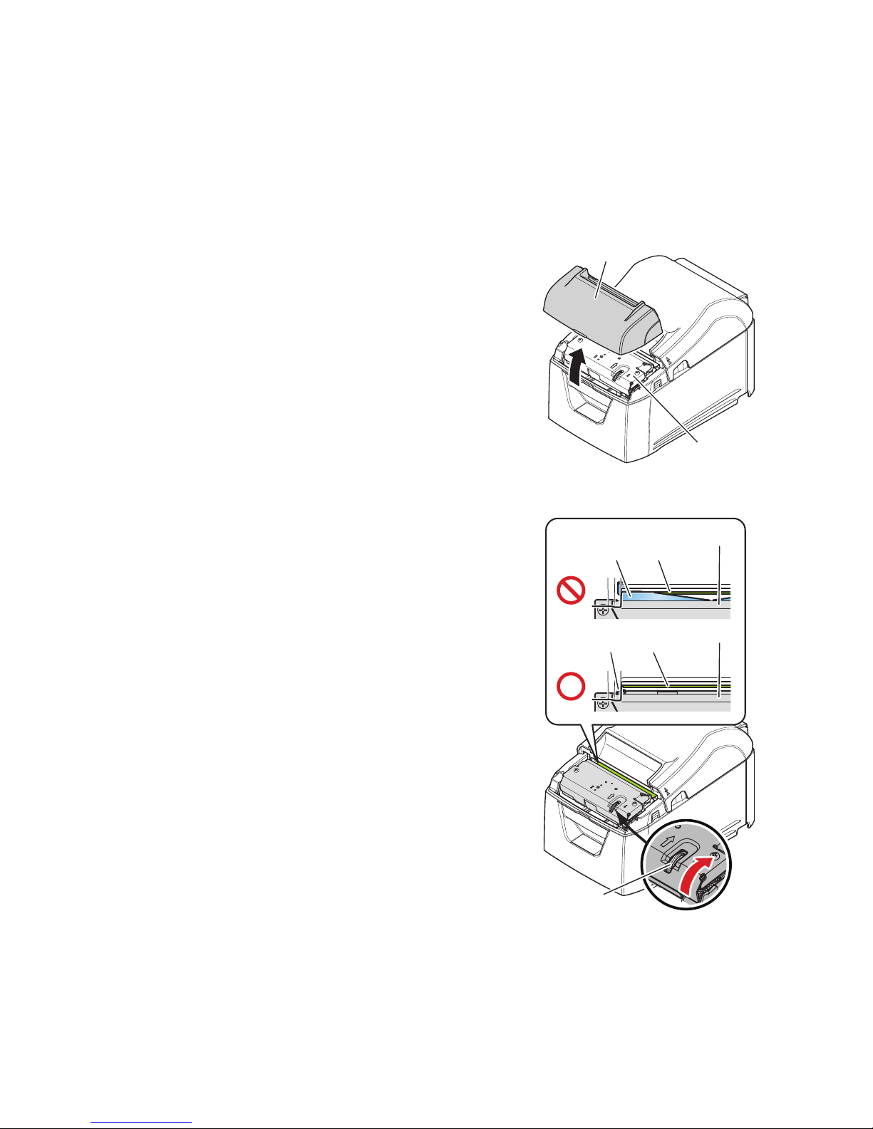
If the auto cutter locks up, restart the printer by turning the power switch off and then back on. A typical locked cutter will be
restored when you restart the printer.
If restarting the printer does not release the locked cutter, follow the procedure below.
Note: Be sure to turn off the printer before performing maintenance on the cutter.
1) Turn the power switch off.
2) Remove the front cover.
3) Remove the jammed paper.
Note: When removing jammed paper, be careful not to
damage the printer.
In particular, the thermal head is easily damaged,
so do not touch it.
4) Turn the knob in front of the cutter in the direction of the red arrow
shown on the right until the rear cover can be opened.
Note: If you can not turn the knob in the direction of
the red arrow, turn it in the opposite direction
until the rear cover can be opened.
5) Open the rear cover, remove the jammed paper, and reset the
paper.
6) Attach the front cover, and turn the power switch on.
Knob
Drive knife
Drive knife
Cutter unit
Cutter unit
Stationary knife
Stationary knife
Front cover
Cutter unit
Page 21
-
18
-
Accumulation of paper dust and dirt may cause the printer to not print portions of characters.
To prevent such problems, perform periodic maintenance, such as removing paper dust from the paper transport section and
removing the blackened paper dust from the thermal head surface.
Note: Turn the printer’s power switch off before performing maintenance.
As a guideline, clean the printer every six months.
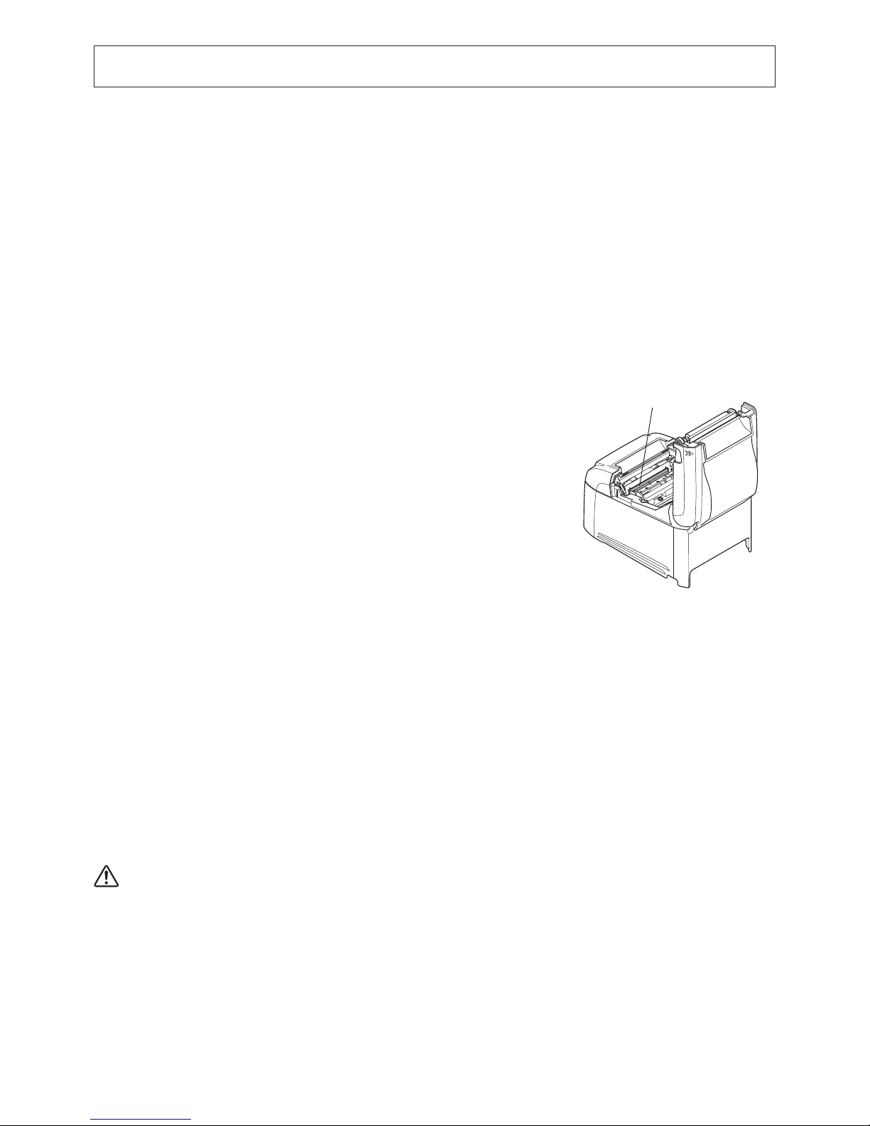
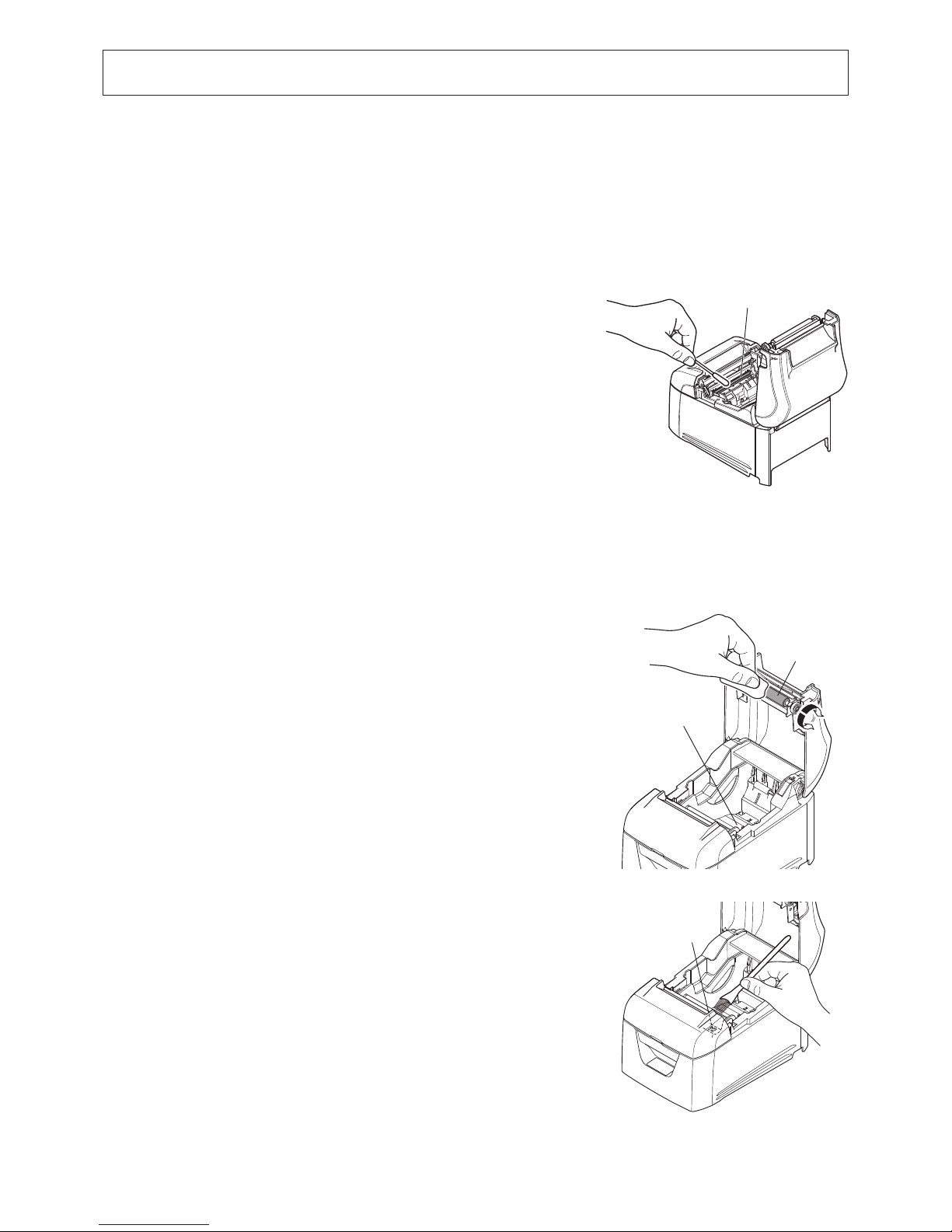
7-1. Thermal Head
7. Maintenance
To remove the blackened paper dust that has accumulated on the thermal head
surface, wipe it clean with a cotton swab (or soft cloth) dipped in alcohol
(ethanol, methanol, or isopropyl).
7-2. Platen Rubber Roller
Using a dry, soft cloth, wipe off the dirt from the rubber roller.
Clean the entire rubber roller by rotating it.
7-3. Paper Holder
Clean the paper holder of debris, dust, paper particles, etc. that may have
accumulated.
Note 1: The thermal head is easily damaged.
Be sure to clean the thermal head with a soft cloth, and be careful not to damage the head.
2: Do not clean the thermal head immediately after printing, when the thermal head is hot.
3: Be careful of static electricity while cleaning the thermal head. Static electricity can damage the head.
4: Turn the power on only after the alcohol has dried completely.
7-4. Sensors and Their Surrounding Area
Clean the sensors of debris, dust, paper particles, etc.
In particular, if the reection sensors are dirty, detection will not be performed
properly.
Cleaning is relatively easy if you use a brush or a similar tool.
Thermal head
Rubber roller
Paper holder
PE sensor
Page 22

 Loading...