

Page 1
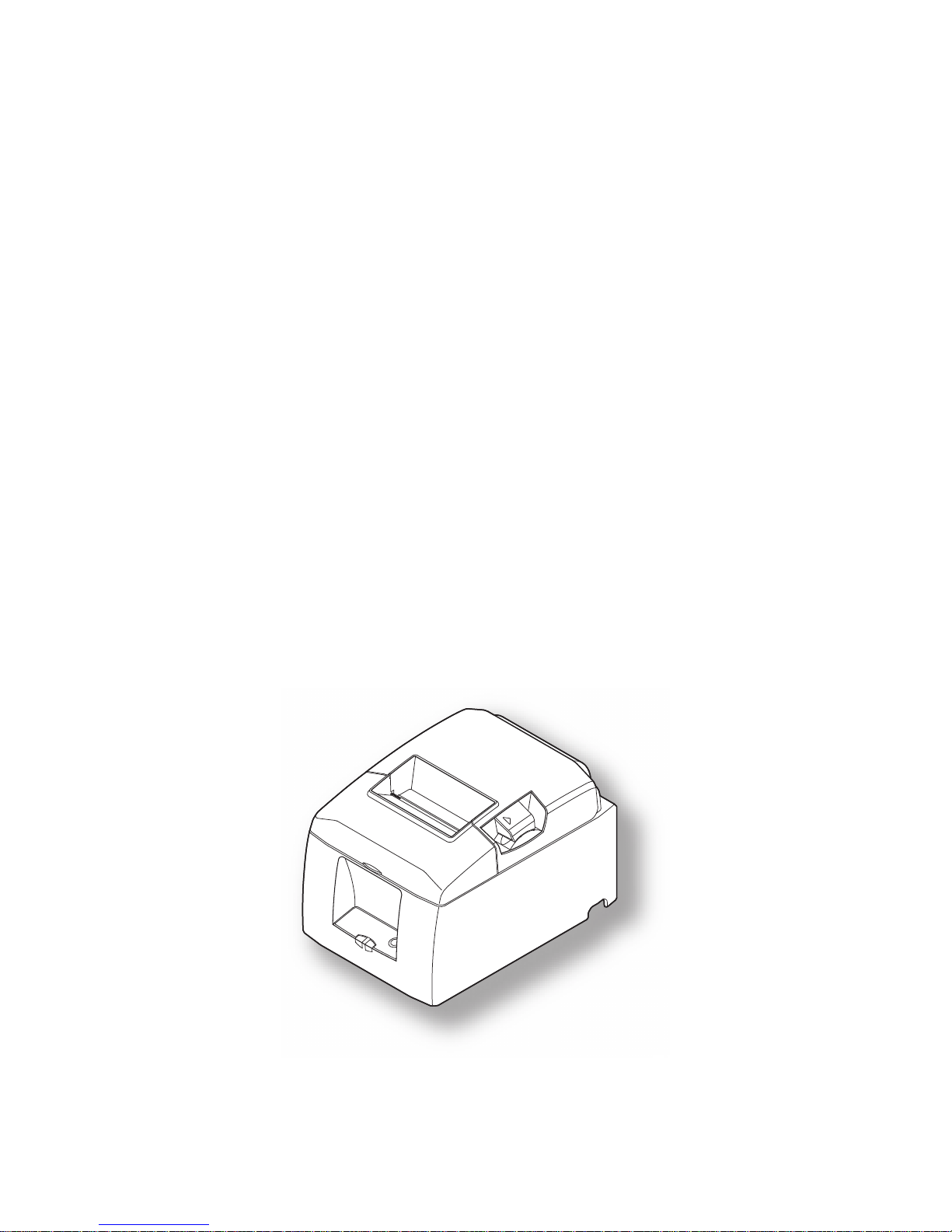
THERMAL PRINTER
PR-TB-650-N
Hardware Manual
Page 2

Federal Communications Commission
Radio Frequency Interference
Statement
This device complies with Part 15 of the FCC Rules. Operation is subject to the following two conditions: (1)
This device may not cause harmful interference, and (2) this device must accept any interference received,
including interference that may cause undesired operation.
NOTE: This equipment has been tested and found to comply with the limits for a Class A digital device,
pursuant to Part 15 of the FCC Rules. These limits are designed to provide reasonable protection against harmful
interference when the equipment is operated in a commercial environment. This equipment generates, uses and
can radiate radio frequency energy and, if not installed and used in accordance with the instruction manual, may
cause harmful interference to radio communications. Operation of this equipment in a residential area is likely to
cause harmful interference in which case the user will be required to correct the interference at his own expense.
For compliance with the Federal Noise Interference Standard, this equipment requires a shielded cable.
This statement will be applied only for the printers marketed in U.S.A.
Statement of
The Canadian Department of Communications
Radio Interference Regulationst
This Class A digital apparatus complies with Canadian ICES-003.
Cet appareil numérique de la classe A est conforme à la norme NMB-003 du Canada.
The above statement applies only to printers marketed in Canada.
Page 3

TABLE OF CONTENTS
1. Unpacking and Installation .....................................................................................................................1
1-1. Unpacking ....................................................................................................................................1
1-2. Choosing a place for the printer ...................................................................................................
2
2. Parts Identification and Nomenclature ..................................................................................................3
2-1. Cutter Model ................................................................................................................................3
2-2. Tear Bar Model
............................................................................................................................3
3. Setup ..........................................................................................................................................................4
3-1. Connecting the Cable to the PC ...................................................................................................4
3-2. Connecting the Cable to the Printer .............................................................................................
4
3-3. Installing the Printer Software
.....................................................................................................6
3-4. Connecting the Optional A
C Adapter ..........................................................................................7
3-5. Turning Po
wer On ........................................................................................................................8
3-6. Connecting to a Peripheral Unit ...................................................................................................
9
3-7. Loading the Paper Roll
..............................................................................................................10
4. Attaching the Accessories ......................................................................................................................14
4-1. Attaching the Holder Plate .........................................................................................................14
4-2. Attaching the Rubber Feet .........................................................................................................
15
4-3. Switch Cov
er Installation ...........................................................................................................16
5. Consumable Parts and AC Adapter .....................................................................................................17
5-1. Thermal Paper Roll ....................................................................................................................17
5-2. AC adapter (option)
....................................................................................................................18
6. Control Panel and Other Functions .....................................................................................................19
6-1. Control Panel..............................................................................................................................19
6-2. Errors ......................................................................................
....................................................19
6-3. Self-Printing ...............................................................................................................................
21
7. Adjusting the Near-end Sensor .............................................................................................................22
8. Preventing and Clearing Paper Jams ...................................................................................................24
8-1. Prev
enting Paper Jams ...............................................................................................................24
8-2. Removing P
aper Jam .................................................................................................................24
8-3. Releasing a Locked Cutter (Auto Cutter Mode only)
................................................................25
9. Periodical Cleaning ................................................................................................................................26
9-1. Cleaning the Thermal Head .......................................................................................................26
9-2. Cleaning the Rubber Roller .......................................................................................................
26
9-3. Cleaning the Paper Holder and the Surrounding
Area ...............................................................26
10. Specifications ........................................................................................................................................27
10-1. General Specifications ................................................................................................................27
10-2. Auto Cutter Specifications .........................................................................................................
28
10-3. Interface
.....................................................................................................................................28
10-4. Electrical Characteristics (AC adapter)
......................................................................................28
10-5. Environmental Requirements
.....................................................................................................29
10-6. Reliability Specifications ...........................................................................................................
30
11. Dip Switch Setting ................................................................................................................................31
11-1. Parallel Interface Model .............................................................................................................32
11-2. RS-232C Interface Model
..........................................................................................................34
12. Parallel Interface ..................................................................................................................................37
Page 4

13. RS-232C Serial Interface .....................................................................................................................38
13-1. Interface Specifications ..............................................................................................................38
13-2. RS-232C Connector ...................................................................................................................39
13-3.
Cable Connections .....................................................................................................................41
14. P
eripheral Unit Drive Circuit .............................................................................................................42
15. Memory Switch Settings
Page 5
– 1 –
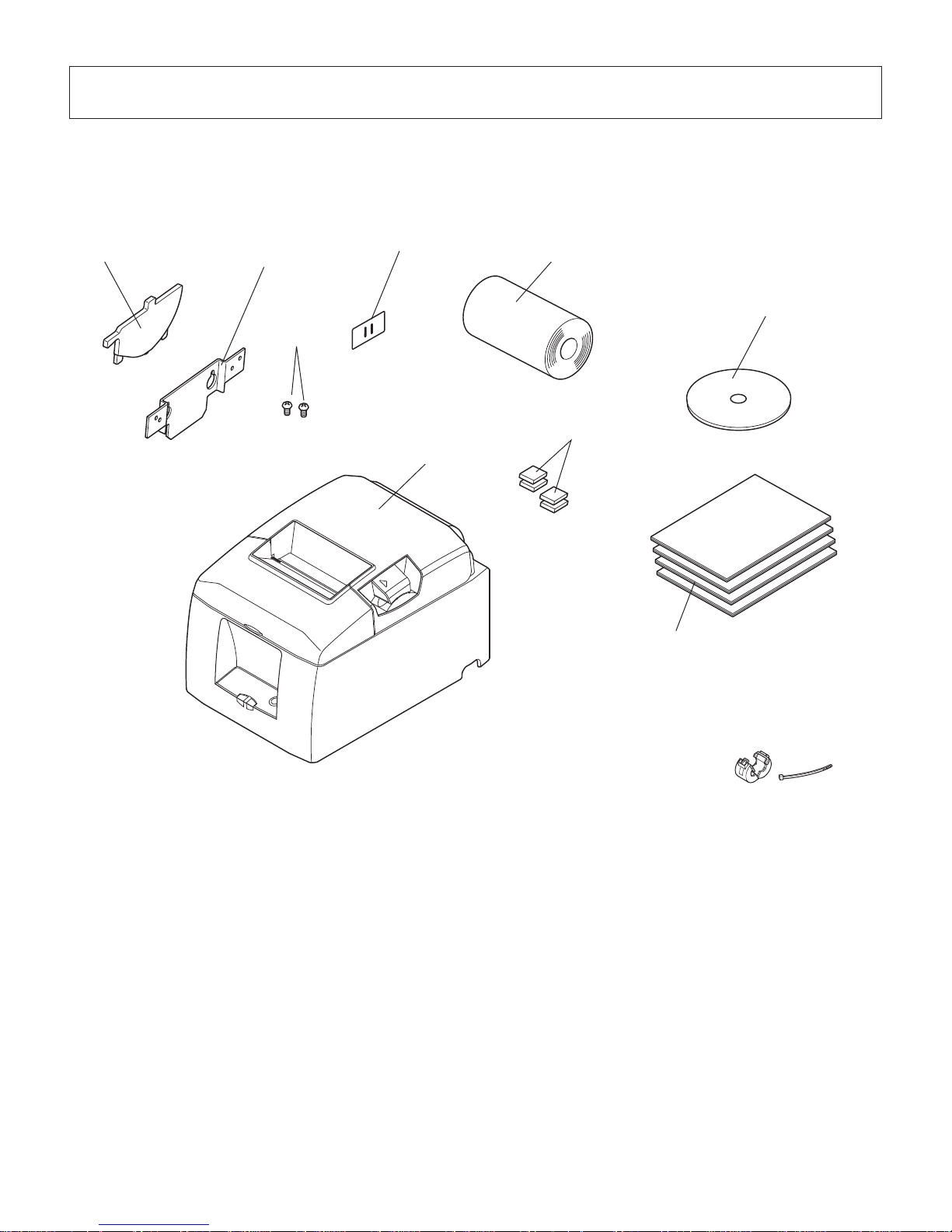
Note
Printer
Holding plate
Screws
Paper roll
Switch blind
Setup sheets
CD-ROM
Paper roll holder
Rubber feet
1. Unpacking and Installation
1-1. Unpacking
After unpacking the unit, check that all the necessary accessories are included in the package.
Note: The ferrite core and fastener provided with your
printer depend on your printer configuration.
Fig. 1-1 Unpacking
If anything is missing, contact the dealer where you bought the printer and ask them to supply
the missing part. Note that it is a good idea to keep the original box and all the packing materials
just in case you need to pack the printer up again and send it somewhere at a later date.
Page 6

– 2 –
1-2. Choosing a place for the printer
Before actually unpacking the printer, you should take a few minutes to think about where
you plan to use it. Remember the following points when doing this.
P Choose a firm, level surf
ace where the printer will not be exposed to vibration.
P The power outlet you plan to connect to for power should be nearby and unobstructed.
P Make
sure that the printer is close enough to your host computer for you to connect
the two.
P
Make sure that the printer is not exposed to direct sunlight.
P Make
sure that the printer is well away from heaters and other sources of extreme
heat.
P Make sure that the surrounding area is clean, dry
, and free of dust.
P Make
sure that the printer is connected to a reliable power outlet. It should not be on
the same
electric circuit as copiers, refrigerators, or other appliances that cause power
spikes.
P Make sure that the room where you are using the printer is not too humid.
WARNING
P Shut down your equipment immediately if it produces smoke, a strange odor, or unu-
sual noise. Immediately unplug the equipment and contact your dealer for advice.
P Never attempt to repair this product yourself. Improper repair work can be dangerous.
P Nev
er disassemble or modify this product. Tampering with this product may result in
injury, fire, or electric shock.
Page 7
– 3 –
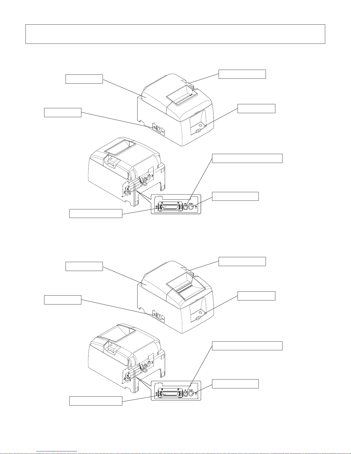
Interface connector
For connection to a
host computer.
Peripheral drive connector
Connects to peripheral units such
as cash drawers, etc.
Do not connect this to a telephone.
Power connector
For connection of the AC adapter.
Never unplug the AC adapter while
the printer is on.
Printer cover
Open this cover to
load or replace paper.
Cover open lever
Push this lever in the direction of the
arrow to open the printer cover.
Power switch
Used to turn on/off
power to the printer.
Control panel
Features LED indicators to
indicate printer status and
switches to operate the printer.
Interface connector
For connection to a
host computer.
Peripheral drive connector
Connects to peripheral units such
as cash drawers, etc.
Do not connect this to a telephone.
Power connector
For connection of the AC adapter.
Never unplug the AC adapter while
the printer is on.
Printer cover
Open this cover to
load or replace paper.
Cover open lever
Push this lever in the direction of the
arrow to open the printer cover.
Power switch
Used to turn on/off
power to the printer.
Control panel
Features LED indicators to
indicate printer status and
switches to operate the printer.
2. Parts Identication and Nomenclature
2-1. Cutter Model
2-2. Tear Bar Model
Page 8
– 4 –
3. Setup
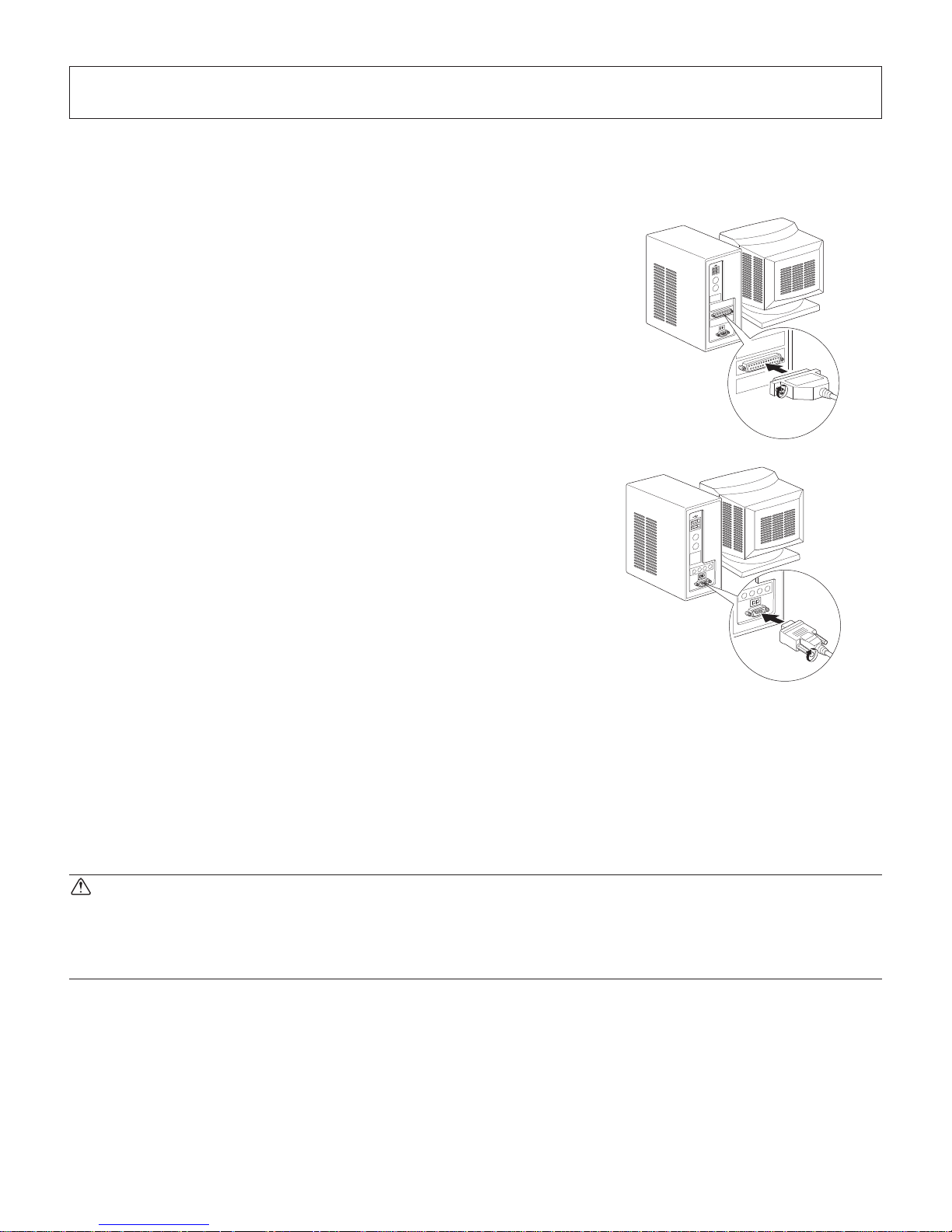
3-1. Connecting the Cable to the PC
3-1-1. Parallel Interface Cable
Connect the parallel interface cable to a parallel port
of your PC.
3-1-2. RS-232C Interface Cable
Connect the
RS-232C interface cable to a RS-232C
port of your PC.
3-2. Connecting the Cable to the Printer
Note that the interface cable is not provided. Please use a cable that meets specifications.
CAUTION
Before connecting/disconnecting the interface cable, make sure that power to the printer and
all the devices connected to the printer is turned off. Also make sure the power cable plug is
disconnected from the AC outlet.
Page 9
– 5 –
Ferrite core
Interface cable
5 cm
(maximum)
Fastener
Parallel interface
cable
RS-232C
interface
cable
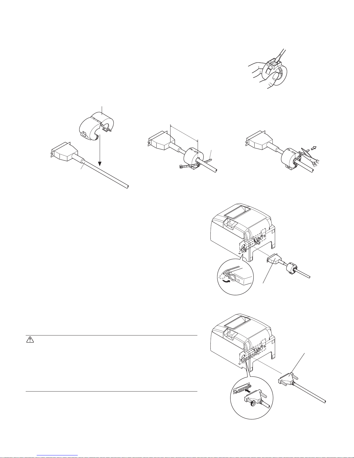
3-2-1. Parallel Interface Cable
(1) Make sure the printer is turn off.
(2) Affix the ferrite core onto the cable as shown in
the illustration.
(3) Pass the f
astener through the ferrite core.
(4) Loop the fastener around the cable and lock it.
Use scissors to cut off any excess.
(5) Connect the
interface cable to the connector on
the rear panel of the printer.
(6) Fasten the connector clasps.
3-2-2. RS-232C Interface Cable
(1) Make sure the printer is turn off.
CAUTION
Before connecting/disconnecting the interface cable, make sure that power to the printer and all the
devices connected to the printer is turned off. Also
make sure the power cable plug is disconnected
from the AC outlet.
(2) Connect the interface cable to the connector on
the rear panel of the printer.
(3) Tighten the connector scre
ws.
Page 10

– 6 –
3-3. This Page Left Intentionally Blank
Page 11
– 7 –
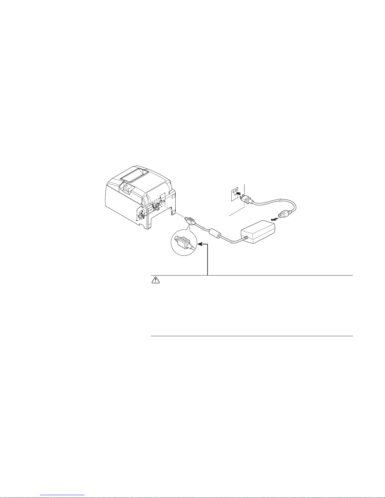
3-4. Connecting the Optional AC Adapter
Note: Before connecting/disconnecting the AC adapter, make sure that power to the printer
and all the devices connected to the printer is turned off. Also make sure the power
cable plug is disconnected from the AC outlet.
(1) Connect the A
C adapter to the power cable.
Note: Use only the standard AC adapter and power cable.
(2) Connect A
C adapter to the connector on the printer.
(3) Insert the power cable plug into an AC outlet.
CAUTION
When disconnecting the cable, take hold of the cable
connector to pull it out. Releasing the lock makes it easy
to disconnect the connector.
Pulling the cable excessively could cause damage to the
connector.
Page 12
– 8 –
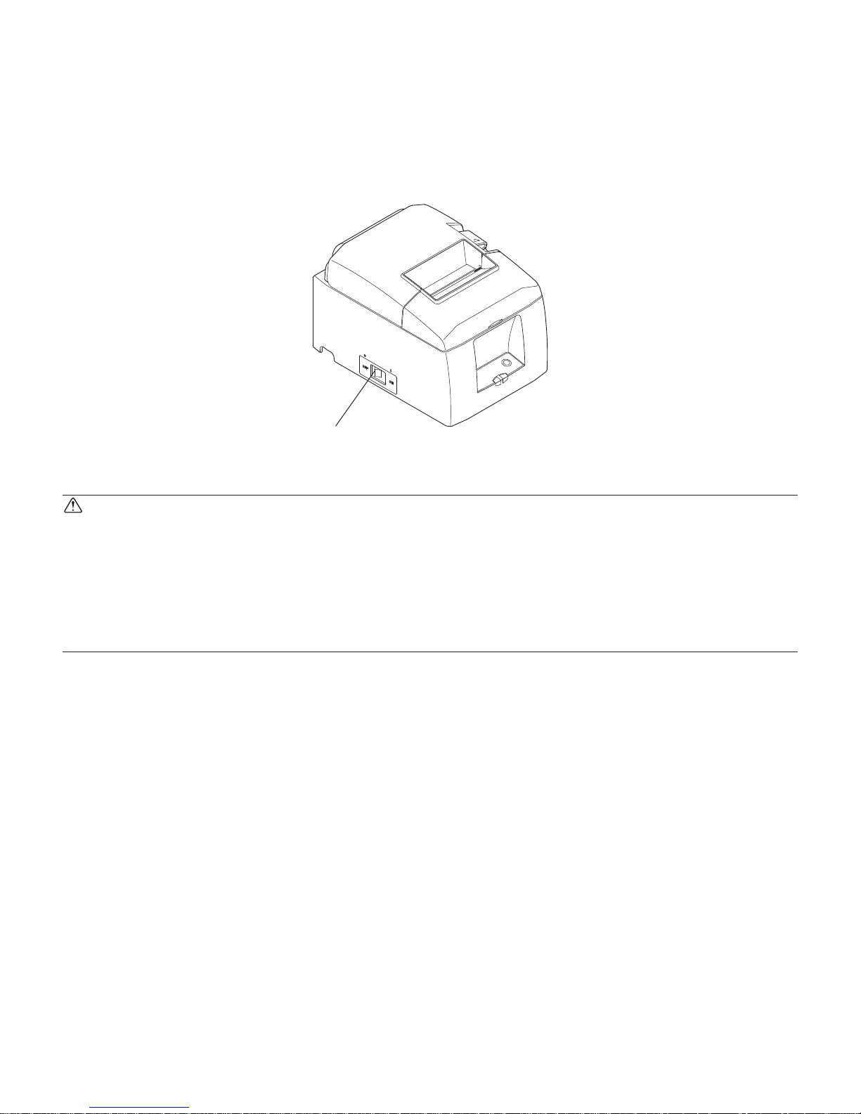
Power switch
3-5. Turning Power On
Make sure that the Power cord has been connected as described in 3-4.
Turn ON the power switch located on the front of the printer.
The POWER lamp on the control panel will light up.
CAUTION
We recommend that you unplug the printer from the power outlet whenever you do not plan to
use it for long periods. Because of this, you should locate the printer so that the power outlet it
is plugged into is nearby and easy to access.
When an Switch blind is affixed to the printer above the power switch, the ON/OFF marks of
the power switch may be hidden. If this occurs, remove the power cord from the outlet to turn
the printer OFF.
Page 13
– 9 –
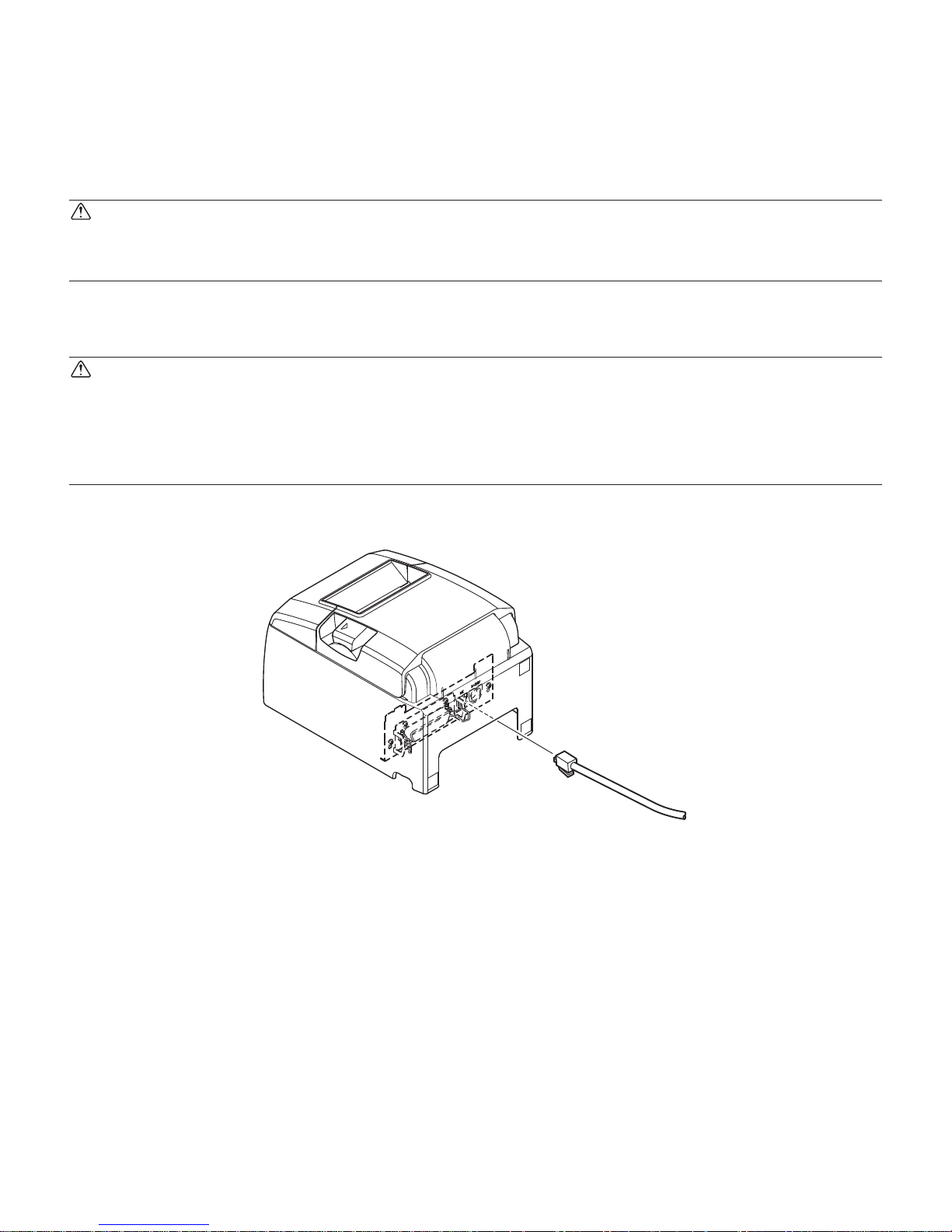
3-6. Connecting to a Peripheral Unit
You can connect a peripheral unit to the printer using a modular plug. See “Modular plug” on
page 42 for details about the type of modular plug that is required. Note that this printer does
not come with a modular plug or wire, so it is up to you to obtain one that suits your needs.
CAUTION
Make sure that the printer is turned off and unplugged from the AC outlet and that the computer
is turned off before making connections.
Connect the peripheral drive cable to the connector on the rear panel of the printer.
CAUTION
Do not connect a telephone line into the peripheral drive connector. Failure to observe this may
result in damage to the printer.
Also, for safety purposes, do not connect wiring to the external drive connector if there is a
chance it may carry peripheral voltage.
Page 14
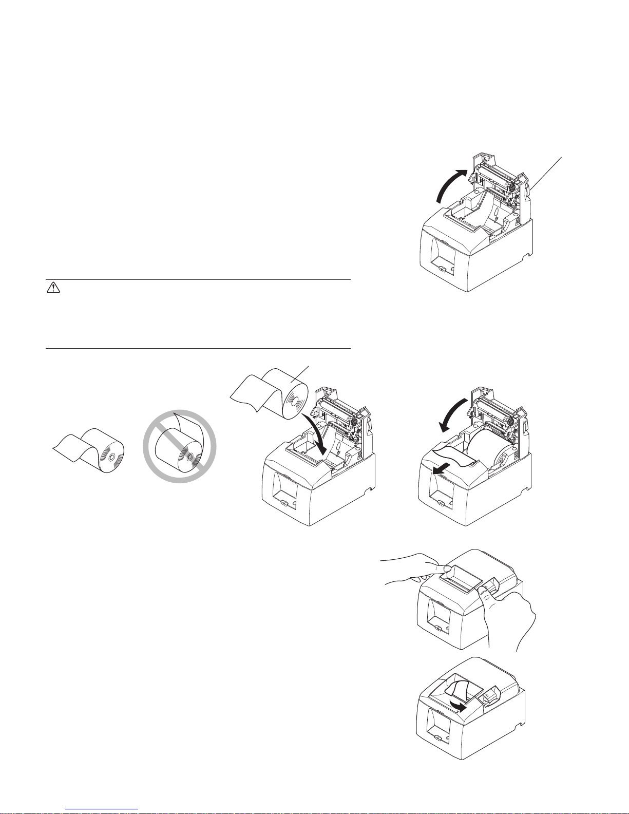
– 10 –
Cover open lever
Paper roll
Tear Bar Model
1) Push the cover open lever, and open the printer
cover.
2) While observing
the direction of the roll, set the
paper roll into the hollow, and pull on the leading
edge of the paper toward you.
CAUTION
Do not pull out the end of the paper diagonally,
as it will cause the paper to become jammed or
skewed.
3) Push down both sides of the printer cover to
close.
Note: Make sure that the printer cover is securely
closed.
4) Tear Bar Model:
Tear off the paper as sho
wn.
Auto Cutter Model:
If the printer
cover is closed after turning on the
power, the cutter operates automatically and the
front end of the paper is cut.
3-7. Loading the Paper Roll
3-7-1. Using 79.5 mm Width Paper Roll
Be sure to use roll paper that matches the printer’s specification.
When using a paper roll with an 57.5 mm width, install the paper roll holder as described on
the following page.
Page 15
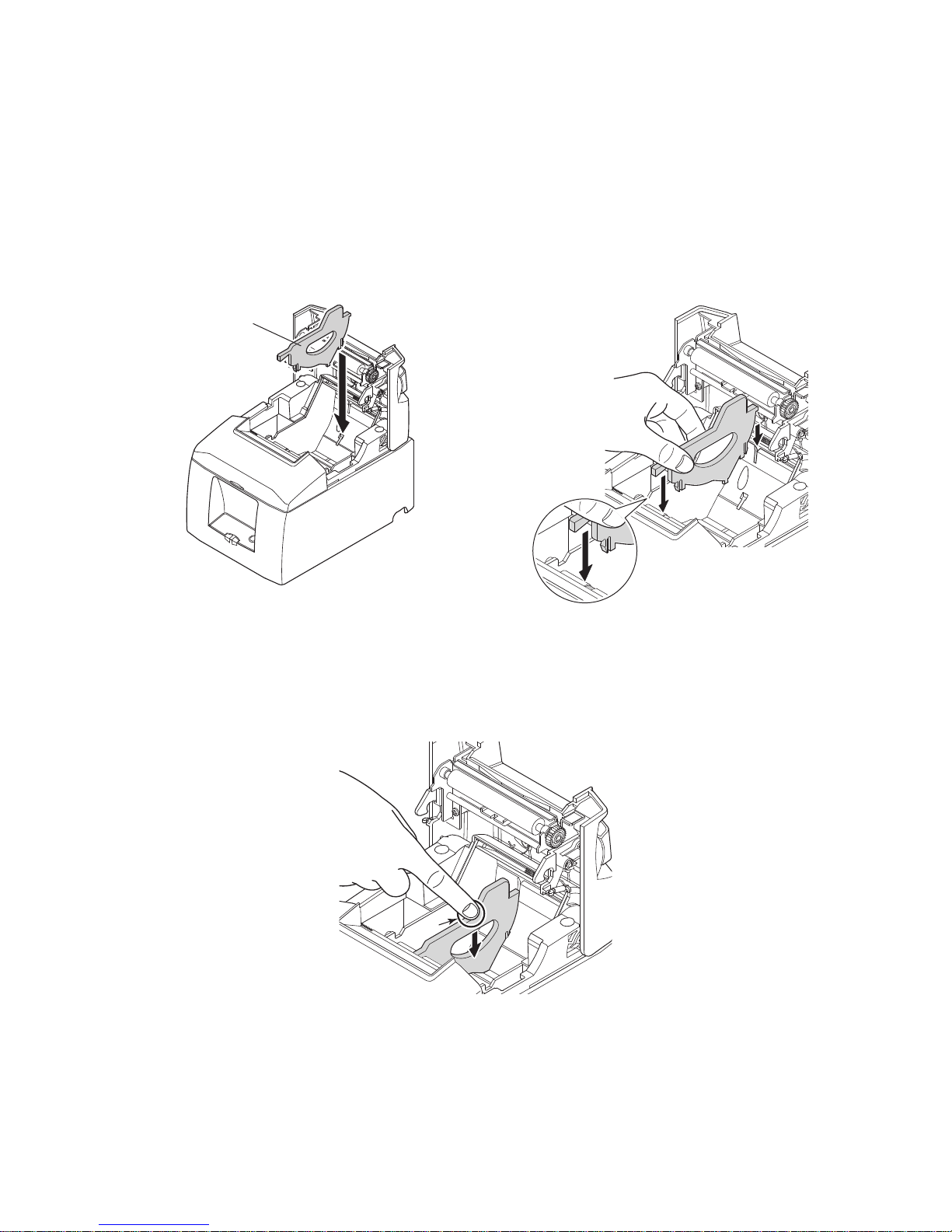
– 11 –
A
Paper Guide
3-7-2. Using 57.5 mm Width Paper Roll
When using a paper roll with 57.5 mm width, install the supplied paper guide on the printer.
To change the effective print width (roll paper width), change the setting at memory switch
configuration Utility. For details on the setting of the memory switches, refer to the software
manual located in the “Documents” folders on the CD-ROM.
1 Insert the paper guide along the groo
ve in the unit as sho
wn.
2 Insert the paper guide by pushing the area marked “A” do
wn until it clicks into place.
Note: After using a paper roll with a width of 57.5 mm, do not change to a paper roll with
a width of 79.5. (This is because the printer head has deteriorated as a result of a
portion of the head having been in direct contact with the platen.)
Page 16

– 12 –
Caution Symbol
This symbol is placed near the thermal head to indicate that it may be hot.
Never touch the thermal head immediately after the printer has been used.
Let the thermal head cool for a few minutes before touching it.
This symbol is placed near the thermal head to indicate that it is easily damaged.
Observe the precautions for handling electrostatic sensitive devices.
WARNING
1) Do not touch the cutter blade.
• There is a cutter inside the paper outlet slot. Not only should you not put your hand in the
paper outlet slot while printing is in progress, never put your hand into the outlet even
when printing is not in progress.
• The printer
cover can be opened when replacing the paper. However, since the cutter
blade is on the inside of the printer cover, be careful not to place your face or hands too
close to the cutter blade.
2) During and
immediately after printing, the area around the thermal head is very hot. Do
not touch it, as you could be burned.
CAUTION
1) Do not operate the cover open lever while pressing on the printer cover with your hand.
2) Do not push the cover open lever and open the printer cover when printing is in progress
or when the auto cutter is operating.
3) Do not push out paper while the printer cover is closed.
4)
The heating element and the driver IC of the thermal head are easily damaged. Do not
touch them with metal objects, sandpaper, etc.
5) Printing quality
may suffer if the thermal head heating element becomes soiled by being
touched with your hands. Do not touch the thermal head heating element.
6) There
is a risk of damage to the driver IC of the thermal head from static electricity. Never
directly touch the IC.
7) The printing
quality and working life of the thermal head cannot be guaranteed if any paper
other than that recommended is used. In particular, paper containing [Na+, K+, C1-] may
drastically reduce the working life of the thermal head. Please exercise caution.
8) Do not
operate the printer if there is moisture on the front surface of the head from con-
densation, etc.
9) A printed
piece of thermal paper may become electrically charged. If the printer is placed
vertically or mounted on a wall, the cut piece of paper may stick to the printer, instead of
falling. Beware that this could cause a problem if you use a stacker that stores the pieces
of paper that fall freely.
10)
Do not
change the paper width during use. The thermal printing head, rubber roller, and
cutter wear differently according to the paper width. This can cause the printing or cutter
movement to malfunction.
11) Do not transport the printer with its co
ver open and holding it by the cover.
12) Do not forcibly pull on the interface cable, power cable, or cash drawer cable that is connected. To detach a connector, make sure to grasp it at the connector portion, without applying excessive stress on the connector at the printer.
Page 17

– 13 –
Notes on Using the Auto Cutter
1) To print after a cut, feed 1 mm (8-dot line) or more of paper.
2) If the cutter is not in its home position after an error, first eliminate the cause of the error;
then, turn the power back ON.
3) A mar
gin of 5 mm or more is recommended from the end of the printed area to the cutting
position.
4) Do not attempt to remo
ve the paper during a cut, as this can cause a paper jam.
Page 18
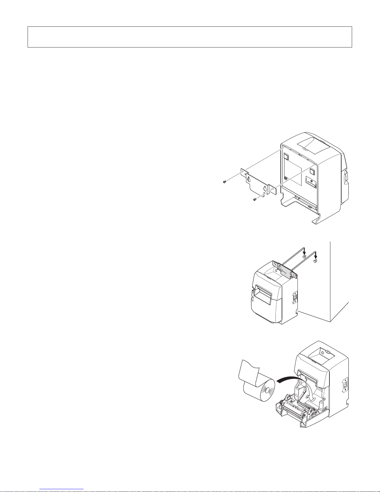
– 14 –
4. Attaching the Accessories
The following accessories do not necessarily have to be attached.
Attach them if necessary.
• Holding plate
• Rubber feet
•
Switch cover
4-1. Attaching the Holder Plate
(1) Attach the holding plate to the printer. Then tighten
the two screws that were supplied to secure it in
place.
(2) Po
sition the printer over the screws, etc., on the wall
and then slide it downward to set it in place.
(3) Push the
cover open lever, and open the printer
cover.
(4) Insert the roll paper as shown.
Page 19
– 15 –
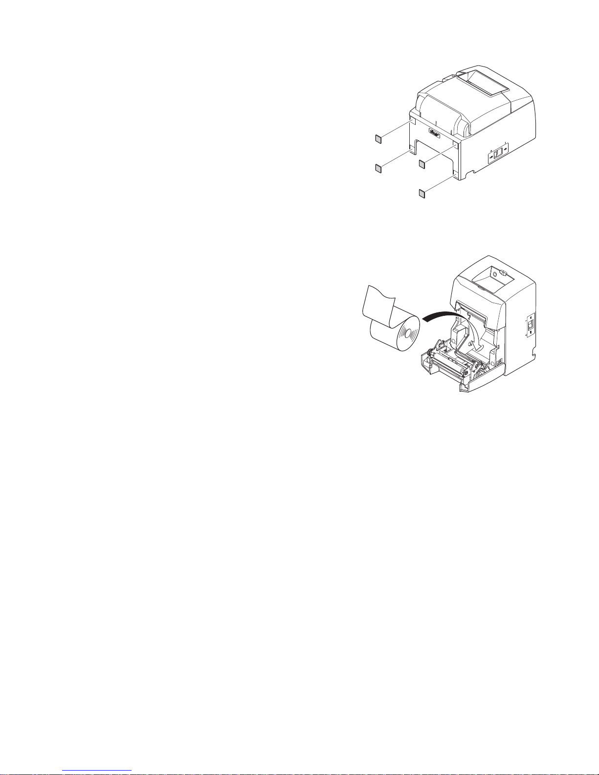
4-2. Attaching the Rubber Feet
(1) Attach the four rubber feet in the positions shown
in the figure.
Ensure that an
y soiling has been completely wiped
off before attaching the rubber feet.
(2) Push the
cover open lever, and open the printer
cover.
(3) Insert the roll paper as shown.
Note:
Depending on the connector shape, the
printer cannot
be positioned vertically when
using the parallel interface.
Page 20
– 16 –
4-3. Switch Cover Installation
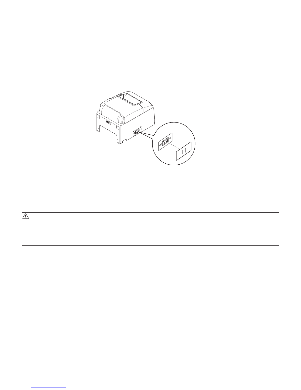
It is not necessary to install the switch cover. Only install it if it is necessary for you. By installing the switch cover, the following become possible.
• Prev
enting the power switch from being operated by mistake.
• Ensuring that other people can not easily operate the power switch.
Install the switch cover as shown in the diagram below.
The power switch can be turned ON (
|
) and OFF (O) by inserting a narrow instrument (ball
pen etc.) in the holes in the switch cover.
CAUTION
We recommend that you unplug the printer from the power outlet whenever you do not plan to
use it for long periods. Because of this, you should locate the printer so that the power outlet it
is plugged into is nearby and easy to access.
Page 21

– 17 –
5. Consumable Parts and AC Adapter
When consumable parts have run out, use those specified in the table below.
Make sure that the
AC adapter specified in the table is used.
Use of consumable parts or AC adapter which are not specified in the table may result in damage to the printer, fire or electric shock.
5-1. Thermal Paper Roll
(1) Paper roll specification
Thermal paper
Thickness: 65~85 µm (excluding Mitsubishi HiTec F5041)
Width: 79.5±0.5 mm (57.5±0.5 mm when the paper roller holder is used)
Outer roll diameter: ø83 mm or less
Take up paper roll width: 80
+0.5
-1
mm or (58
+0.5
-1
mm when the paper roller holder is used)
Core outer/inner diameter
Core outer Core inner
ø18±1 mm ø12±1 mm
Printed surface: Outer edge of roll
Tail end handling: Do not use paste or glue to secure the roll paper or its core.
Do not fold the tail end of the paper.
(2) Recommended paper
Manufacturer Product name Quality characteristics/Use
Paper thickness
(µm)
Mitsubishi Paper Mills
Limited
P220AG normal type paper 65 (thickness)
HP220A high image stability paper 65 (thickness)
HP220AB-1 high image stability paper 75 (thickness)
P220AGB normal type paper, card ticket 80 (thickness)
PB670 2 color paper: Red & Black 75 (thickness)
PB770 2 color paper: Blue & Black 75 (thickness)
Mitsubishi HiTec Paper
Flensburg GmbH
F5041 normal type paper 60 (thickness)
Oji Paper Co., Ltd. PD150R normal type paper 75 (thickness)
PD160R high image stability paper 65/75 (thickness)
PD750R 2 color paper: Red & Black 75 (thickness)
PD700R 2 color paper: Blue & Black 75 (thickness)
Nippon Paper Industries TF50KS-E2C normal type paper 65 (thickness)
Kanzaki Specialty Papers
Inc. (KSP)
P320RB 2 color paper: Red & Black 65 (thickness)
P320BB 2 color paper: Blue & Black 65 (thickness)
Page 22
– 18 –
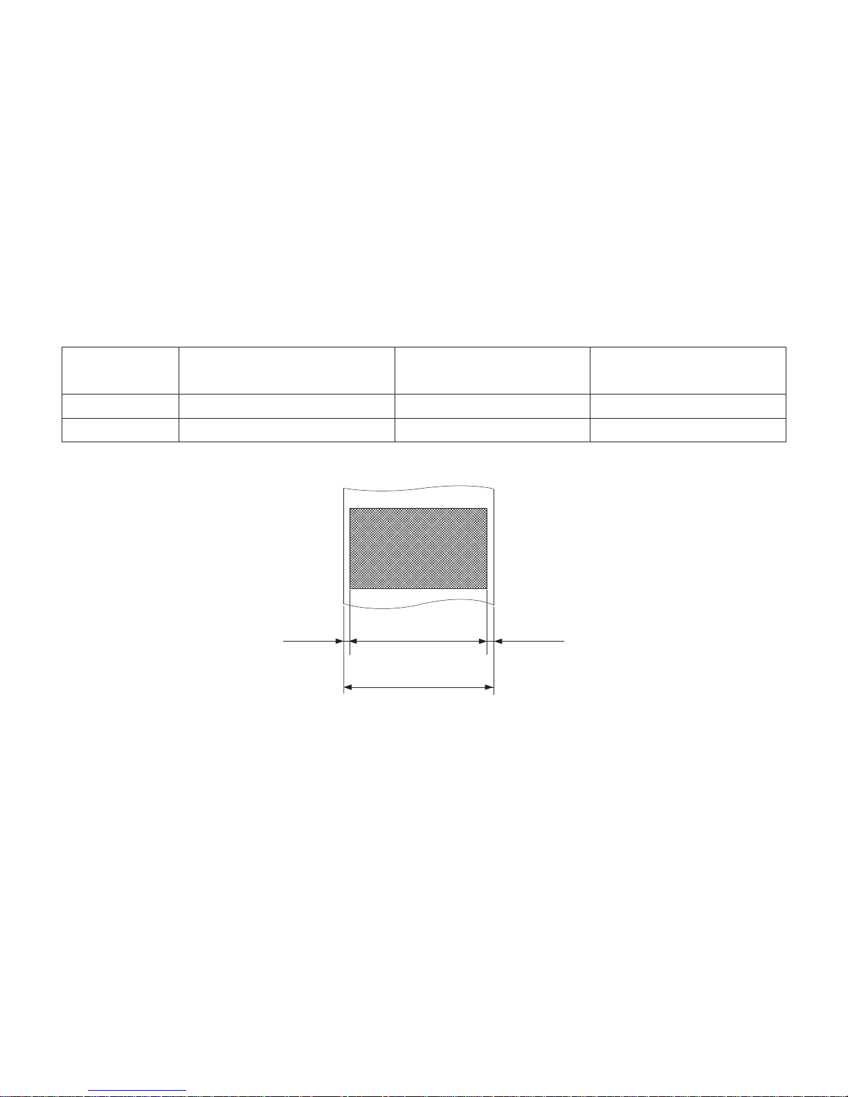
Left Margin Right MarginEffective Print Width
Paper Width
5-2. AC adapter (option)
AC adapter which are not specified may result in damage to the printer, fire or electric shock.
Model name: PS60A-24A
Input: 90 to 264 V AC, 50/60 Hz
Output: DC24 V ±5%, 2.0 A (5.0 A Load 10 sec. Max.)
Note:
1) Depending on
the type and thickness of the paper, it may be necessary to change the
settings for printing darkness. To change the darkness settings, use the printing darkness settings command <ESC><RS> ‘d’ n or the memory switch. Please consult the
dealer for details.
2)
The print
density may vary depending on the type of paper roll and operating environ-
ment.
3) A reader
or scanner may not be able to scan a printed bar code or characters depending
on the print density. Make sure that your reader or scanner is able to scan correctly
beforehand.
(3) Effecti
ve Print Width
Paper Width
(mm)
Right / Left Margin (mm) Effective Print Width
(mm)
Number of Print Columns (12 × 24 Font)
79.5 ± 0.5 3.75 72 48
57.5 ± 0.5 Left 2.75, Right 3.75 51 34
Page 23

– 19 –
ERROR
FEED
POWER
3 FEED button
2 ERROR lamp (Red LED)
1 POWER lamp (Green LED)
6. Control Panel and Other Functions
1 POWER lamp (Green LED)
Lights when the power is ON.
2 ERROR lamp (Red LED)
Indicates various errors in combination
with POWER lamp.
3
FEED b
utton
Press the FEED button to feed roll pa-
per.
Error Description POWER Lamp ERROR Lamp Recovery Conditions
Head high temperature
detection
Flashes at 0.5-second intervals
OFF Automatically recovered after
the print head has cooled.
Cover open error ON ON Automatically recovered by clos-
ing the printer cover.
Paper out error ON Flashes at 0.5
second intervals
Automatically recovered by
loading a new paper roll, then
closing the printer cover.
Paper near end ON Flashes at 2 sec-
ond intervals
Indicators show that the paper
end is approaching, but the
printer continues to print.
Paper cut error OFF Flashes at 0.125
second intervals
Recovered if the cutter returns to
the home position after turning
the power OFF and ON. (See
Notes 1 and 2.)
Note:
1) If the cutter doesn’t return to the home position or doesn’t perform the initial movement, it cannot be recovered. See “8-3. Releasing a Locked Cutter (Auto Cutter Mode
only)” on page 25 for details.
2) If the paper is
jammed, turn the power off, clear the jammed paper, then turn the power
ON.
Page 24

– 20 –
2) Non-recoverable errors
Error Description POWER Lamp ERROR Lamp
Recovery Conditions
Flash access error OFF Flashes at 0.5-
second intervals
This is not a recoverable error.
EEPROM error OFF Flashes at 0.75-
second intervals
This is not a recoverable error.
SRAM error OFF Flashes at 1-sec-
ond intervals
This is not a recoverable error.
Head thermistor error OFF Flashes at 1.5-
second intervals
This is not a recoverable error.
Power voltage error OFF Flashes at 2-sec-
ond intervals
This is not a recoverable error.
Note:
1) If a non recoverable error occurs, turn the power OFF immediately.
2) When Power supply error occurs, there is a possibility that the power supply unit has
a trouble.
For other non recov
erable errors, please consult the dealer for repairs.
Page 25
– 21 –
6-3. Self-Printing
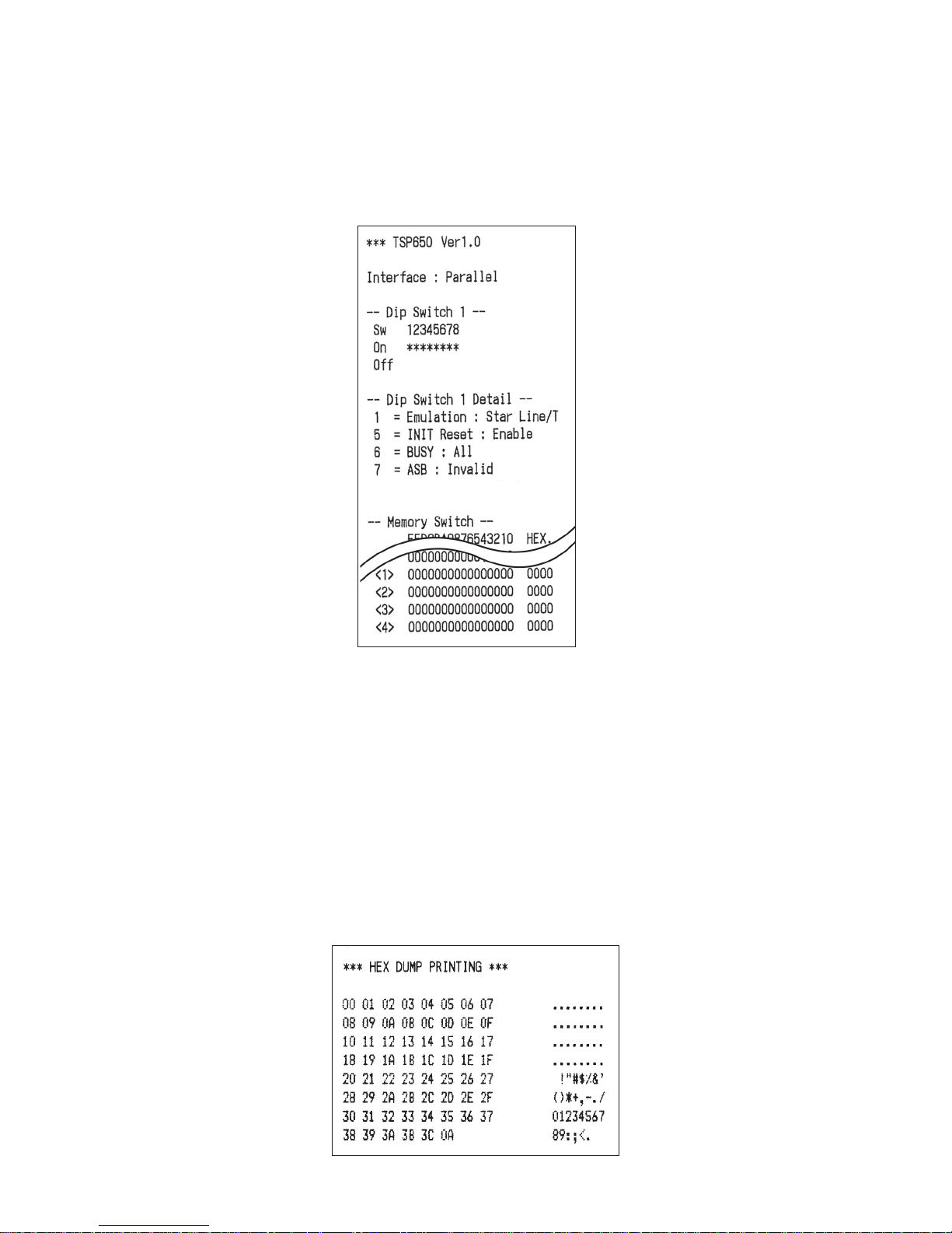
6-3-1. Test Printing
Place the thermal paper roll on the printer.
Turn the power ON while holding the FEED button depressed. The printer will run a test print
according to the Ver. No., DIP switch settings, and memory switch settings, etc.
6-3-2. Hexadecimal Dump Mode
Place the thermal paper roll on the printer.
Open the printer co
ver, then turn the power on while holding the FEED button.
When the cover is closed, “*** HEX DUMP PRINTING ***” is printed, and the printer enters
the Hexadecimal Dump Mode.
Each of the signals sent from the computer to the printer will be printed out in hexadecimal
code.
This function allows you to check if a control code sent to the printer by the program being used
is correct or not. The final line is not printed if its data is less than one full line. However, if
the FEED button is pushed, the final line is printed. To turn off the mode, it is necessary to turn
off the printer completely.
Page 26
– 22 –
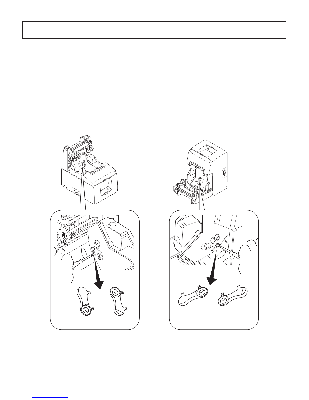
(Level 1) (Level 2)
[Horizontal Layout]
[Vertical Layout or Wall-Mount]
(Level 2) (Level 1)
7. Adjusting the Near-end Sensor
Use the following procedure to adjust the near-end sensor so it is compatible with the size of
paper roll you are using.
1 Open the printer cover
.
2 Determine the diameter
of the paper roll you are using and find the required setting in the
table below.
3 Insert the tip of a ballpoint pen or similar object into the hole of the adjuster, and then push
and slide the adjuster to the desired setting.
When changing the
setting, make sure that the position of the hole is aligned with the align-
ment mark indicated by the arrow.
Page 27
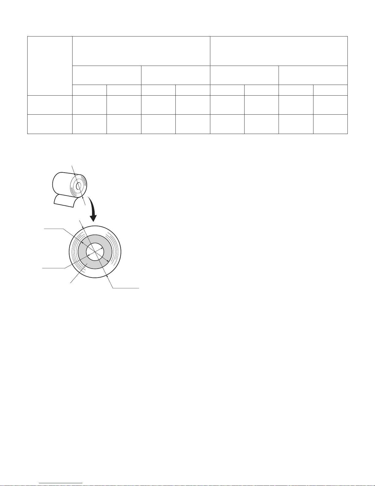
– 23 –
C
C
B
A
Paper roll core
Adjustment value according to the paper you are using
Paper Width
(µm)
Horizontal (standard) Layout
ø12 (A) inner diameter / ø18 (B) outer di-
ameter core roll paper
Vertical Layout or Wall-Mount
ø12 (A) inner diameter / ø18 (B) outer di-
ameter core roll paper
Detected diameter (C)
(mm)
Remaining paper
length (m)
Detected diameter (C)
(mm)
Remaining paper
length (m)
Level 1 Level 2 Level 1 Level 2 Level 1 Level 2 Level 1 Level 2
65 Approx.
ø23
Approx.
ø29
Approx.
2.5
Approx.
6.3
Approx.
ø23
Approx.
ø29
Approx.
2.5
Approx.
6.3
85 Approx.
ø23
Approx.
ø29
Approx.
1.9
Approx.
4.8
Approx.
ø23
Approx.
ø29
Approx.
1.9
Approx.
4.8
Notes:
1) The adjuster is factory-set at level 1.
2) The detected diameter and remained paper length given
in the table are calculated values, and there are some
variances depending on the rolled state of the paper,
the actual mechanism, or the printing pattern.
3)
If thick paper is used (paper thickness between
80 µm
and 85 µm), the paper roll may loosen and
cause variances in the detected values. Therefore,
setting the adjuster to Level 2 is recommended.
Page 28
– 24 –
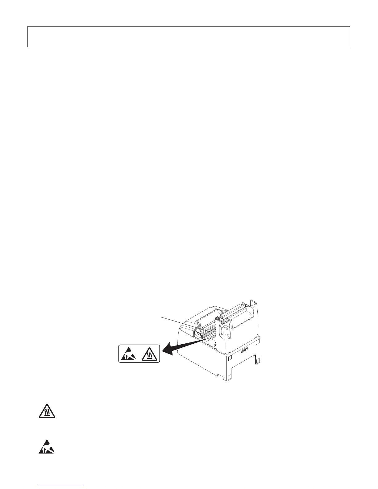
Thermal head
8. Preventing and Clearing Paper Jams
8-1. Preventing Paper Jams
The paper should not be touched during ejection and before it is cut.
Pressing or pulling the paper during ejection may cause a paper jam, paper cutting failure or
line feed failure.
8-2. Removing Paper Jam
If a paper jam occurs, clear it as described below.
(1) Set the power switch to off to turn off power to the printer.
(2) Push the lever toward you to open the printer cover.
(3) Remove the jammed paper.
Note: To prevent parts such as the thermal head or the rubber roller from damage or
deformation, do not forcibly pull on the paper with the printer cov
er closed.
(4) Position the paper roll straight and close the printer cov
er gently.
Note 1: Make sure
that the paper is positioned straight. If the printer cover is closed with
the paper skewed, a paper jam may result.
Note 2: Lock the printer
cover by pressing down on the sides. Do not try to close it by
pressing down on the centre. The cover may not lock properly.
(5) Set the
power switch to on to turn on power to the printer. Make sure that the ERROR LED
is not lit.
Note: While the ERROR LED is lit, the printer will not accept any commands such as
the print command, so make sure that the printer cover is locked properly.
Caution Symbol
This symbol is placed near the thermal head to indicate that it may be hot.
Never touch the thermal head immediately after the printer has been used.
Let the thermal head cool for a few minutes before touching it.
This symbol is placed near the thermal head to indicate that it is easily damaged.
Observe the precautions for handling electrostatic sensitive devices.
Page 29
– 25 –
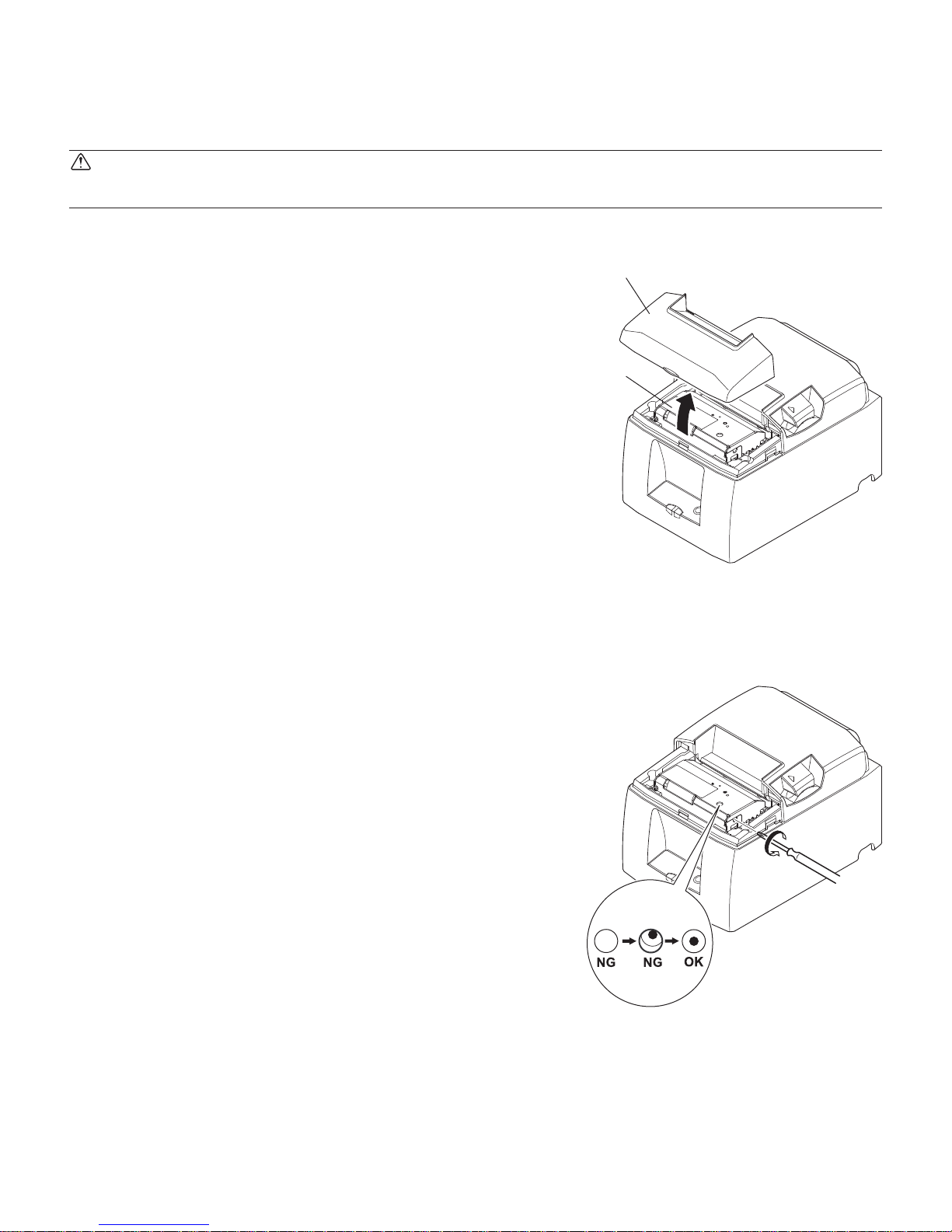
Auto cutter
Front cover
8-3. Releasing a Locked Cutter (Auto Cutter Mode only)
If the auto cutter locks up or fails to cut the paper, follow the steps below.
WARNING
Since working on the cutter may be dangerous, be sure to turn off the printer first.
(4) If the cutter is locked, insert a Philips screwdriver
into the Philips screw hole on the side of the cutter,
and turn it in the direction of the arrow shown on
the right, in order to return the cutter to its normal
position.
(5)
Open the
printer cover, remove any jammed paper,
and then reinstall the paper roll.
(6) Install the
front cover, and then set the power
switch to ON.
(1) Set the
power switch to OFF to turn off the print-
er.
(2)
Remov
e the front cover to reveal the auto cutter.
(3) Remove any jammed paper.
Note: Be careful not to damage the printer while
removing an
y jammed paper.
Since the thermal
print head is particularly
sensitive, be sure not to touch it.
Page 30
– 26 –
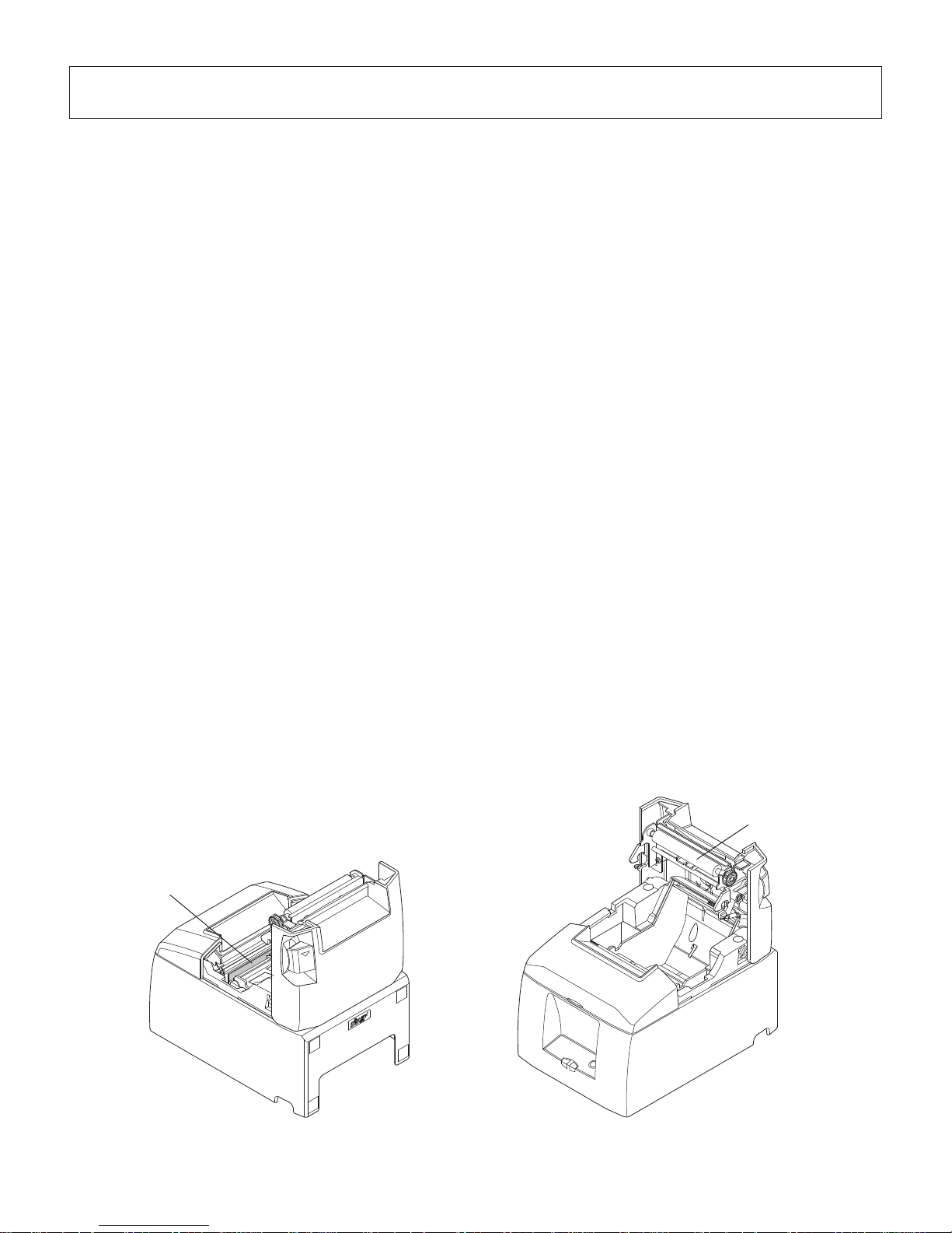
Thermal head
Rubber roller
9. Periodical Cleaning
Printed characters may become partially unclear due to accumulated paper dust and dirt. To
prevent such a problem, paper dust collected in the paper holder and paper transport section
and on the surface of the thermal head must be removed periodically.
Such cleaning is recommended to be carried out once six month or one million lines.
9-1. Cleaning the Thermal Head
To remove the dark paper dust that has accumulated on the thermal head surface, wipe it clean
with cotton swab (or soft cloth) dipped in alcohol (ethanol, methanol, or isopropyl alcohol).
Note 1: The thermal head
is easily damaged, so clean it with a soft cloth, taking care not
to scratch it.
Note 2: Do not attempt to clean the thermal head immediately after printing, when the
thermal head is hot.
Note 3: Bew
are of the risk of damaging the thermal head as a result of static electricity
that may be created during cleaning.
Note 4: Turn the po
wer ON only after the alcohol has dried completely.
9-2. Cleaning the Rubber Roller
Use a dry, soft cloth to wipe off the dust that may have accumulated on the rubber roller.
Rotate the platen to clean the entire surface.
9-3. Cleaning the Paper Holder and the Surrounding Area
Clean the paper holder of debris, dust, paper particles, glue, etc. that may have accumulated.
Page 31
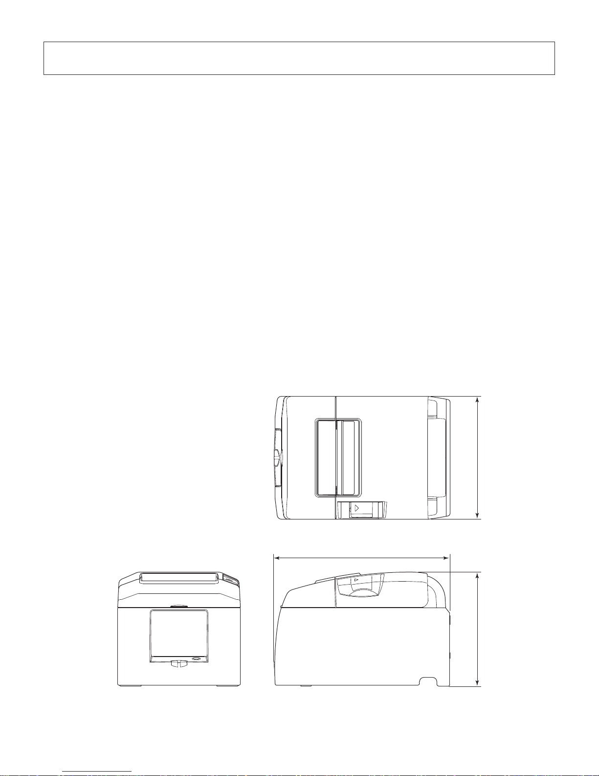
– 27 –
142 mm
132 mm
202 mm
10. Specications
10-1. General Specifications
(1) Printing method Direct line thermal printing
(2) Print speed Max. 1200 dots/sec. (150 mm/sec.)
(3) Dot density 203 dpi: 8 dots/mm (0.125 mm/dot)
(4) Printing width Max. 72 mm
(5) Number of print columns 48 (12 × 24 dots)
(6) Paper feed method Friction feed
(7) Paper roll Refer to chapter 5 for details on the recommended paper
roll.
Paper width: 79.5 ± 0.5 or 57.5 ± 0.5 mm
Roll diameter: ø83 mm or less
(8) Overall dimension 142 (W) × 202 (D) × 132 (H) mm
(9) Weight Auto cutter model : 1.72 kg (without roll paper)
Tear bar model : 1.56 kg (without roll paper)
(10) Noise Auto cutter model : Approx. 50 dB
Tear bar model : Approx. 53 dB
Page 32

– 28 –
<Viewed from Connector Surface>
10-2. Auto Cutter Specifications
(1) Cutting Modes Partial cut (leaves one uncut portion in center of paper)
(2) Cutting Duty Min. 3 seconds/cut
(3) Thickness of paper 0.065 ~ 0.085 mm
10-3. Interface
RS-232C serial interface / Two-way parallel interface (IEEE1284)
10-4. Electrical Characteristics (AC adapter)
(1) Input: 100 to 240 V AC, 50/60 Hz
(2) Output: DC 24 V ± 5%
(3) Current Consumption (DC 24 V at room temperature)
Standby: Approx. 0.15 A
ASCII printing: Approx. average 1.7 A
(Approx. 17.5% printing rate)
100% print duty: Approx. peak 9.0 A
(Solid printing): Approx. average 5.0 A
(Continuous solid printing should be 10 seconds or less.)
(4) Power Connector
Pin No. Function
1 Drive power (24 V)
2 Signal GND
3 N.C.
Shell Frame ground
Note:
• When using a printer power supply other than the optional AC adapter (PS60A-24A
series), be sure that the following cautions are observed.
• Use a
power supply of DC 24 V ± 5% and more than 2.0 A (5.0 A Load 10 sec. Min.)
with SELV output and LPS or Class 2 output approved by IEC60950.
• Be careful
about installing the printer in an area where there is noise. Take the appropri-
ate measures to protect against electrostatic AC line noise, etc.
Page 33
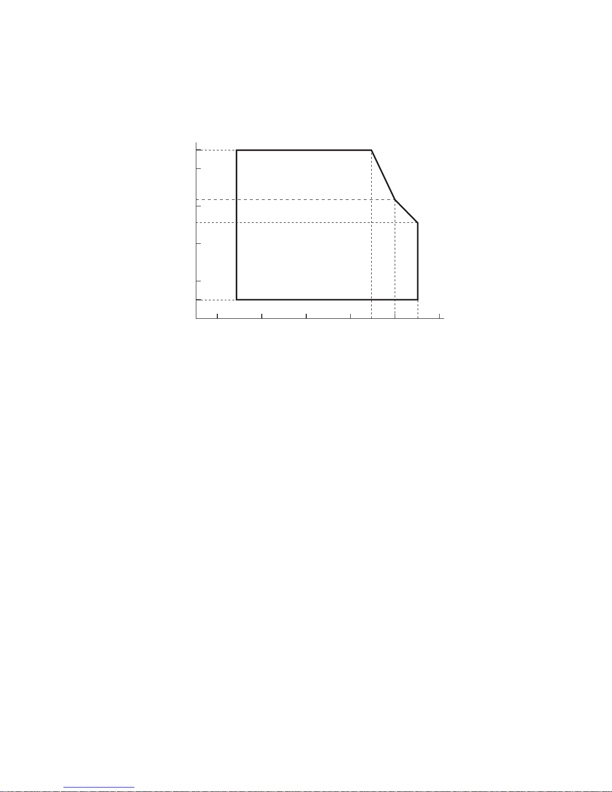
– 29 –
(%RH)
34°C90% RH
40°C65% RH
45°C50% RH
90
80
60
40
20
10
0 10 20 30 40 50
Temperature (°C)
Operating temperature and humidity range
Relative humidity
Operating environment
range
10-5. Environmental Requirements
(1) Operating
Temperature 5°C to 45°C
Humidity 10% to 90% RH (without condensation)
(2) Transport/storage (except for paper)
Temperature -20°C to 60°C
Humidity 10% to 90% RH (without condensation)
* However, the combination of 40°C and 90% RH (no condensation) is considered the worst
value regarding high temperatures and humidity.
Page 34

– 30 –
10-6. Reliability Specifications
1) Life Mechanical: 20 million lines
Head: 100 million pulses, 100 km (±15% max. average head resistance
fluctuation)
F
or 2-color printing, 50 million pulses, 50 km (±15% max. aver-
age head resistance fluctuation)
Auto cutter: 1
million cuttings (provided the paper thickness is between 65
and 85 µm)
<Conditions>
Average printing ratio:
12.5%
Recommended thermal paper: 65 µm
2) MCBF: 60 million lines
The Mean Cycle Between Failure (MCBF) is defined to be the overall failure cycle, which
includes random or wear failures that occur until the printer reaches its mechanical life of
20 million lines.
* As the
mechanical remains at 20 million lines, the MCBF of 60 million lines does not
indicate its useful life.
3) Auto Cutter (Life)
1 million cuttings (provided the paper thickness is between 65 and 85
µm)
* All the
reliability values indicated above are based on the use of the recommended thermal
paper. No reliability can be guaranteed for the use of non-recommended thermal paper.
Page 35
– 31 –
11. Dip Switch Setting
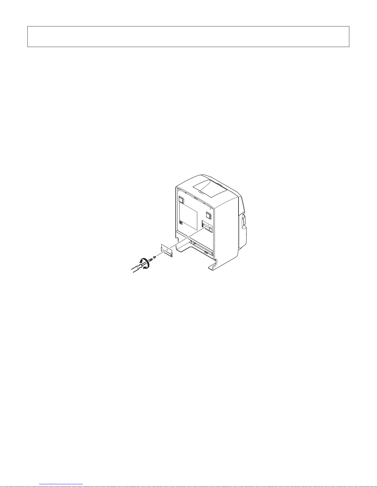
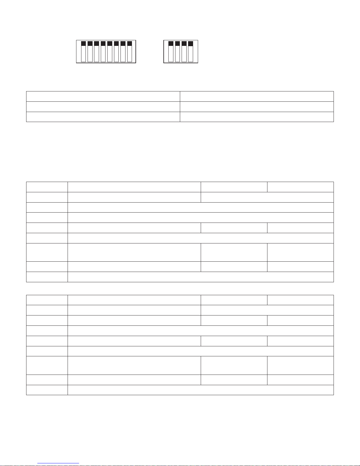
Two DIP switches are provided at the bottom of the printer, and can be set as given in the table
below. Be sure to set the power switch to off before changing the settings. It is recommended
to use a pointed item like a pen or flat-blade driver screw to change the settings. The settings
will become effective when the power switch is set to on again.
The following is the procedure for changing the settings on DIP switches.
1.
Make sure the printer is turned of
f.
2. Remove the screw from the DIP switch blind. Then take off the DIP switch blind, as shown
in the illustration below.
3. Set the switches using a pointed tool, such as a pen or flat-blade screwdri
ver.
4. Replace the DIP switch blind. Then secure it with the screw.
The new settings take effect when you turn on the printer.
Page 36
– 32 –
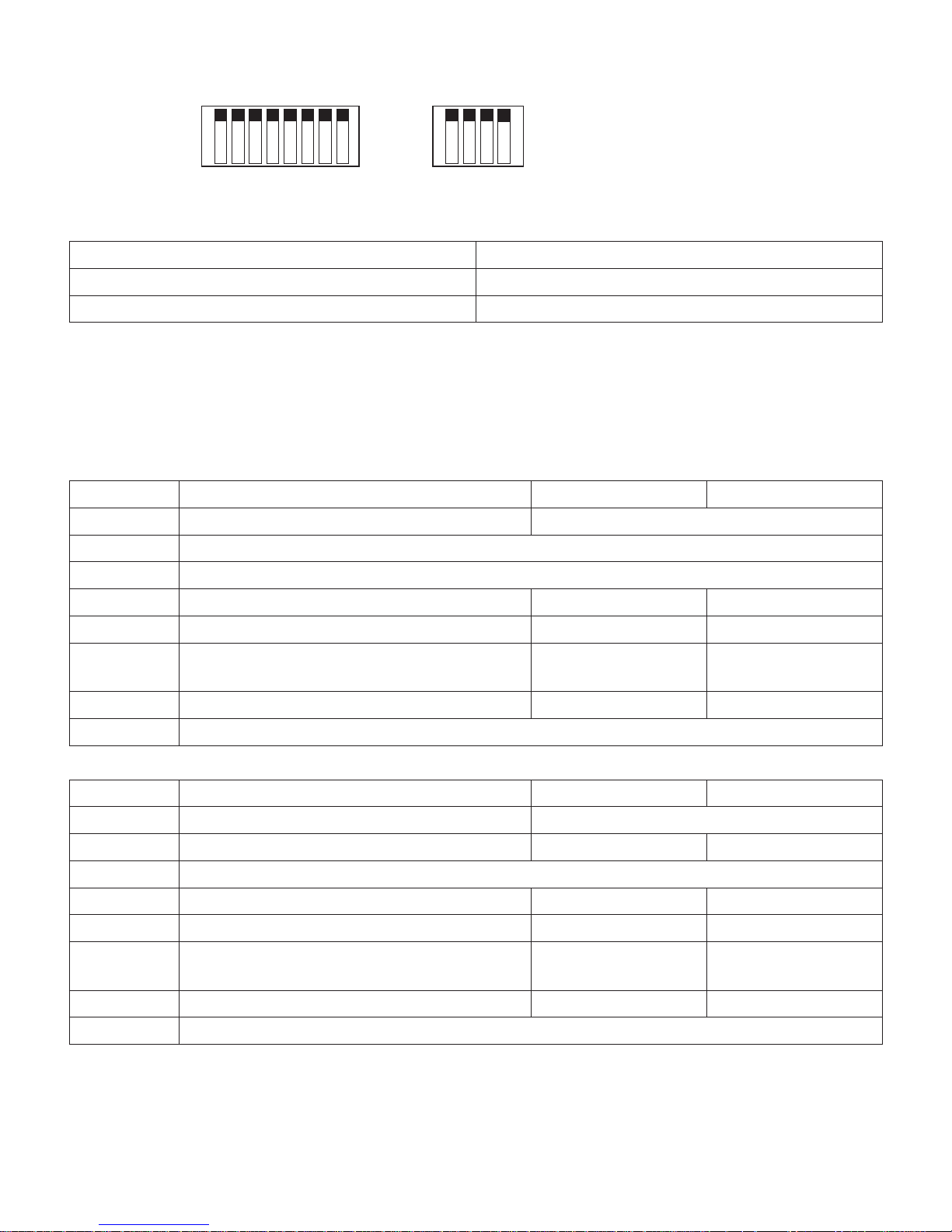
No. 1 2 3 4 5 6 7 8 No. 1 2 3 4
DIP-SW 1 DIP-SW 2
11-1. Parallel Interface Model
ON ON
OFF OFF
DIP-SW 1
Switch 1-1 Command emulation
ON Star Mode
OFF ESC/POS Mode
The factory settings of DIP switch are all on.
The functions of switches 1-2 through 1-8 will change according to the command emulation
that has been set using switch 1-1.
(1) Star mode
Switch Function ON OFF
1-1 Command emulation Always ON
1-2 Should not be changed (Should be set to on)
1-3 Should not be changed (Should be set to on)
1-4 Sensor adjustment Invalid Valid
1-5 Pin #31 (INIT) reset signal Valid Invalid
1-6 Handshaking conditions
(conditions for BUSY)
Offline or receive
buffer full
Receive buffer full
1-7 Automatic status back function Invalid Valid
1-8 Should not be changed (Should be set to on)
(2) ESC/POS mode
Switch Function ON OFF
1-1 Command emulation Always OFF
1-2 Graphic adjustment 203 DPI 180 DPI
1-3 Should not be changed (Should be set to on)
1-4 Sensor adjustment Invalid Valid
1-5 Pin #31 (INIT) reset signal Valid Invalid
1-6 Handshaking conditions
(conditions for BUSY)
Offline or receive
buffer full
Receive buffer full
1-7 Automatic status back function Invalid Valid
1-8 Should not be changed (Should be set to on)
Page 37

– 33 –
DIP-SW 2
Switch Function ON OFF
2-1
Always ON Should be set to on
2-2
2-3
2-4
The factory settings of DIP switch are all on.
Page 38
– 34 –
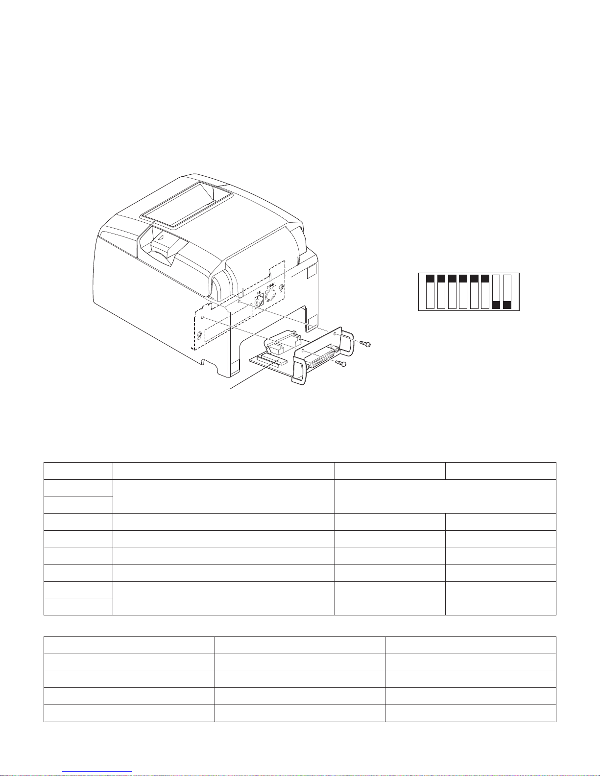
No. 1 2 3 4 5 6 7 8 No. 1 2 3 4
DIP-SW 1 DIP-SW 2
11-2. RS-232C Interface Model
ON ON
OFF OFF
DIP-SW 1
Switch 1-1 Command emulation
ON Star Mode
OFF ESC/POS Mode
The factory settings of DIP switch are all on.
The functions of switches 1-2 through 1-8 will change according to the command emulation
that has been set using switche 1-1.
(1) Star mode
Switch Function ON OFF
1-1 Command emulation Always ON
1-2 Should not be changed (Should be set to on)
1-3 Should not be changed (Should be set to on)
1-4 Sensor adjustment Invalid Valid
1-5 Should not be changed (Should be set to on)
1-6 Handshaking conditions
(conditions for BUSY)
Offline or receive
buffer full
Receive buffer full
1-7 Automatic status back function Invalid Valid
1-8 Should not be changed (Should be set to on)
(2) ESC/POS mode
Switch Function ON OFF
1-1 Command emulation Always OFF
1-2 Graphic adjustment 203 DPI 180 DPI
1-3 Should not be changed (Should be set to on)
1-4 Sensor adjustment Invalid Valid
1-5 Should not be changed (Should be set to on)
1-6 Handshaking conditions
(conditions for BUSY)
Offline or receive
buffer full
Receive buffer full
1-7 Automatic status back function Invalid Valid
1-8 Should not be changed (Should be set to on)
Page 39

– 35 –
DIP-SW 2
Switch Function ON OFF
2-1
Always ON Should be set to on
2-2
2-3
2-4
The factory settings of DIP switch are all on.
Page 40
– 36 –
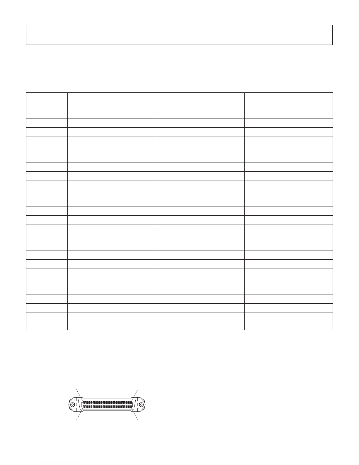
DIP switch 3
No. 1 2 3 4 5 6 7 8
ON
OFF
DIP-SW 3
The following is the procedure for changing the settings on DIP switch No. 3.
1. Turn off the printer and all components connected to it.
2. Remove the 2 screws.
3. Remove the serial interface board unit.
4. Change the setting of the DIP switches.
5. Replace the serial interface board unit.
Then secure it with the screws.
6. Turn on the printer and all components connected to it.
The factory settings of DIP switch are all on, except for switches 7 and 8.
DIP-SW 3
Switch Function ON OFF
3-1
Baud Rate See table below
3-2
3-3 Data Length 8 bits 7 bits
3-4 Parity Check Disabled Enabled
3-5 Parity Odd Even
3-6 Handshake DTR/DSR XON/XOFF
3-7
Should not be changed (Should be set to
off)
— —
3-8
Baud Rate Switch 3-1 Switch 3-2
4800BPS OFF ON
9600BPS ON ON
19200BPS ON OFF
38400BPS OFF OFF
Page 41
– 37 –
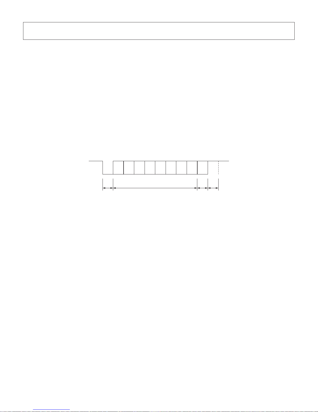
(1 9 )
(1 )
(3 6 )
(1 8 )
Parallel interface connector (printer side)
This connector mates with an
Amphenol 57-30360 connector
12. Parallel Interface
The two-way parallel interface is compatible with the IEEE1284 compatibility mode and nibble
mode. Contact your dealer for details.
Table of Connection Signals for Each Mode
Pin No. Direction
Compatibility Mode
Signal Name
Nibble Mode
Signal Name
1 In nStrobe Host Clock
2 In/Out Data0 Data0
3 In/Out Data1 Data1
4 In/Out Data2 Data2
5 In/Out Data3 Data3
6 In/Out Data4 Data4
7 In/Out Data5 Data5
8 In/Out Data6 Data6
9 In/Out Data7 Data7
10 Out nAck PtrClk
11 Out Busy PtrBusy/Data3,7
12 Out PError AckDataReq/Data2,6
13 Out Select Xflag/Data1,5
14 — HostBusy
15 — —
16 Signal GND Signal GND
17 Frame GND Flame GND
18 OUT +5 V +5 V
19~30 Twisted Pair Return Twisted Pair Return
31 In nInit nInit
32 Out nFault nDataAvail/Data0,4
33 External GND —
34 — —
35 — —
36 In nSelectIn 1284Active
Note:
1. The prefix “n” on the signal name refers to low active signals. If the host does not
have any one of the signal lines listed above, two-way communication fails.
2. For interf
acing, signal lines should always use twisted pair cables with the return
sides connected to the signal ground level.
Page 42
– 38 –
A: Start bit
B: Data bit
C: Parity bit
D: Stop bit
A B C D
b0 b1 b2 b3 b4 b5 b6 (b7)
MARK “1”
SPACE “0”
13. RS-232C Serial Interface
13-1. Interface Specifications
1 Data transmission method: Asynchronous serial interface
2 Baud rate: Selectable from 4800, 9600, 19200, 38400 bps
(Refer to “11. DIP Switch Setting”.)
3
Word length Start bit: 1 bit
Data bit: 7 or 8 bits (selectable.)
Parity bit: Odd, even or none (selectable.)
Stop bit: 1 bit length
4 Signal polarity RS-232C
MARK: Logic “1” (–3
V to –15 V)
SPACE: Logic “0” (+3 V to +15 V)
Page 43

– 39 –
13-2. RS-232C Connector
Pin No. Signal name Direction Function
1 F-GND — Frame ground
2 TXD OUT Transmission data
3 RXD IN Receive data
4 RTS OUT Always SPACE
5 N/C Not used.
6 DSR IN 1) STAR Mode
Not used.
2) ESC/POS Mode
When DIP Switch 3-7 = OFF;
A) DTR/DSR communication mode
Indicates whether data receive from host is enabled or
disabled.
Space: Receive enabled
Mark: Receive disabled
(except when transmitting data by DLE EOT, and GS a)
B) X-ON/X-OFF communication mode
Status of this signal is not checked.
When DIP Switch 3-7 = ON;
This is an externally reset signal.
A space above 1 ms pulse width engages reset.
7 S-GND — Signal ground
8~19 N/C Not used.
20 DTR OUT 1) STAR Mode
A) DTR/DSR communication mode
Indicates whether data receive from host is enabled or
disabled.
Space: Receive enabled
Mark: Receive disabled
B) X-ON/X-OFF communication mode
Alw
ays space, except during following condi-
tions:
• Period between
reset and communication ena-
bled
• During self printing
Page 44
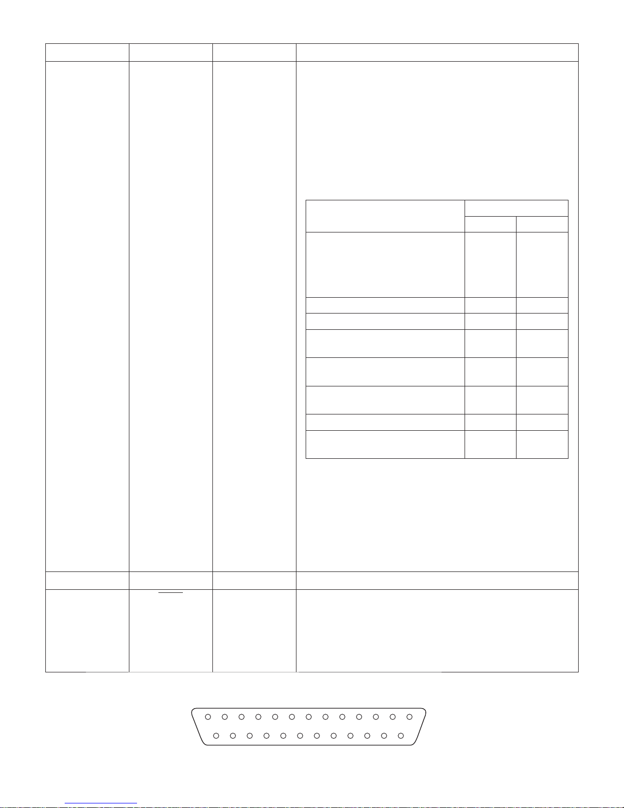
– 40 –
13
25
1
14
D-sub 25 Pin
Pin No. Signal name Direction Function
2) ESC/POS Mode
A) DTR/DSR communication mode
Indicates whether data receive from host is enabled or
disabled.
Space: Receive enabled
Mark: Receive disabled
The busy condition can be changed by using Memory
switch as follows:
Printer status
Memory SW 4-4
1 0
1. Du
ring the period from when
the power is turned on (including resetting using the interface)
to when the printer is ready to
receive data.
BUSY BUSY
2. During the self printing. BUSY
BUSY
3. When the cover is open. — BUSY
4. During the paper feeding by
FEED button.
— BUSY
5. When the printer stops printing
due to a paper-end.
— BUSY
6. During macro
executing standby
status.
— BUSY
7. When an error has occurred. — BUSY
8. When the receive buffer becomesfull.
BUSY BUSY
B) X-On/X-Off Communication Mode
Always space, except during following condi-
tions:
• Period between
reset and communication ena-
bled
• During self printing
21~24 N/C Not used.
25
INIT IN When DIP Switch 3-8 = OFF;
Status of this signal is not checked.
When DIP Switch 3-8 = ON;
This is an externally reset signal.
A space above 1 ms pulse width engages reset.
Page 45

– 41 –
1
2
3
4
5
6
1
2
3
4
5
6
7
8
20
FG FG
TXD
RXD
RTS
CTS
DSR
20
25
7
SG
DTR
INIT
3
2
7
8
6
5
1
4
TXD
RXD
RTS
CTS
DSR
SG
DCD
DTR
Printer side Host side
25 pin 9 pin
13-3. Cable Connections
The followings are a recommended interface cable connections.
Note: Use shielded wire less than 3 m in length.
Page 46
– 42 –
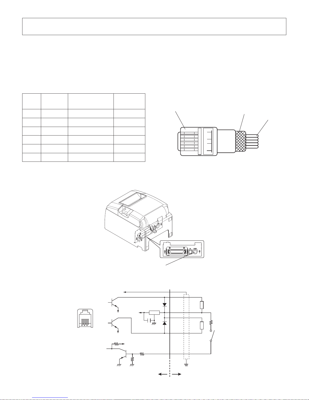
Peripheral drive connector
1 6
Wire lead
Modular plug: MOLEX 90075-0007,
AMP641337, or BURNDY B-66-4
Shield
Modular plug
Pin
No.
Signal
name
Function I/O
direction
1 FG Frame ground —
2 DRD1 Drive signal 1 OUT
3 +24 V Drive power OUT
4 +24 V Drive power OUT
5 DRD2 Drive signal 2 OUT
6 DRSNS Sense signal IN
Drive circuit
The recommended drive unit is shown below.
6 1
1
2
3
4
5
6
F.G
D1
D2
TR1
TR2
TR3
R2
+24 V
7824
R1
+5 V
M-GND
M-GND
L1
L2
6-P Modular
jack connector
With shield
Peripheral unit
Peripheral
unit 2
Compulsion
switch
Frame
ground
R3
4.7 kΩ
1/4 W
14. Peripheral Unit Drive Circuit
Peripheral unit drive circuit connector only connects to peripheral units such as cash drawers,
etc.
Do not connect it to a telephone.
Use cables which meet the following specifications.
Peripheral Drive Connector
User sidePrinter side
Page 47

– 43 –
R3 = 3.5 kΩ
R4 = 300 Ω
Drive Output: 24 V, Max. 1.0 A
TR1, TR2: Transistor 2SD 1866 or equivalent
R1=10 kW
R2=33 kW
Reference
2SD 1866 Circuit Conguration
Notes:
1. Peripheral units 1 and 2 cannot be driven simultaneously. To drive them
continuously, set the duty cycle ratio to 20% or less (excluding an externally
connected buzzer).
2. The following e
xternal buzzer is available as an option.
External buzzer model: RMB-24
Voltage rating: 24V
A
verage consumption current: Max. 21 mA (at 24V)
Sound pressure: Min. 75 dB at 1 m
Lead wires: red (+) black (-)
3. Never use the external buzzer command if you connect a device (such as a
cash drawer) other than an external buzzer. It could damage the connected
device and the printer circuit. Refer to the separate Programmer's Manual for
details on commands.
4. The status of the compulsion switch can be known from the status command.
Refer to the separate Programmer's Manual for details.
5. Minimum resistance for coils L1 and L2 is 24
W
.
6.
Absolute maximum ratings for diodes D1 and D2 (Ta = 25°C) are:
Average Rectified Current I
o
= 1A
7. Absolute maximum rating for transistors TR1 and TR2 (Ta = 25°C) are:
Collector current I
C
= 2.0 A
Page 48
– 44 –
15. Memory Switch Settings
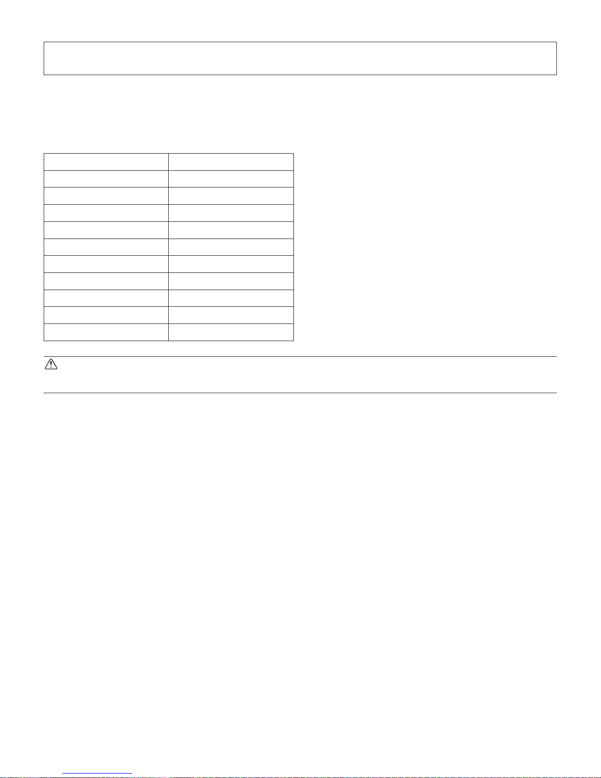
Each memory switch is stored in EEPROM. For details on the functions and settings of memory
switches, please consult the dealer.
The table below shows the factory settings for the memory switches.
Memory Switch Hexadecimal Code
0 0000
1 0000
2 0000
3 0000
4 0000
5 0000
6 0000
7 0000
8 0000
9 0000
WARNING
Changing the memory switch settings can cause the printer to fail to operate correctly.
Page 49

 Loading...