


PolyVision®
Interactive Whiteboard
Installation and Operation Guide
Part number 370-0254-00
©2008 PolyVision Corporation
All rights reserved

Information in this document is subject to change without notice.
Reproduction in any manner without written permission of PolyVision
Corporation is forbidden.
PolyVision is a registered trademark of Steelcase, Inc. Walk-and-Talk
and Lightning are trademarks of PolyVision Corporation.
PolyVision Corporation reserves the right to make changes in product
design, or detail, and to discontinue any product or material without
notice.
This product is covered by one or more of the following patents:
Canada 2,100,624; EPO 600,576; EPO 871,935; Germany
69,321,445; US 4,777,329; US 5,248,856; US 5,327,161; US
5,434,370; US 5,583,323; US 5,585,605; US 5,665,942; US
5,790,114; US 5,838,309 US 6,353,193; US 6,355,895; US
6,445,384; Other patents pending.

Table of Contents
Overview . . . . . . . . . . . . . . . . . . . . . . . . . . . . . . . . . . . . . . . . . . . . . . . . . . 3
Options and Considerations . . . . . . . . . . . . . . . . . . . . . . . . . . . . . . . . . . . . 4
Register Your PolyVision Whiteboard . . . . . . . . . . . . . . . . . . . . . . . . . . 4
Installing Your Walk-and-Talk Whiteboard . . . . . . . . . . . . . . . . . . . . . . . . . . 5
What Comes in the Box . . . . . . . . . . . . . . . . . . . . . . . . . . . . . . . . . . . 6
Preparing to Mount the Whiteboard . . . . . . . . . . . . . . . . . . . . . . . . . 6
Mounting the Whiteboard. . . . . . . . . . . . . . . . . . . . . . . . . . . . . . . . . 9
PolyVision Driver Installation (WT Models) . . . . . . . . . . . . . . . . . . . . . . 10
System Requirements . . . . . . . . . . . . . . . . . . . . . . . . . . . . . . . . . . 10
Driver Installation for Walk-and-Talk Models . . . . . . . . . . . . . . . . . . 10
LED and Status Messages on the Walk-and-Talk Whiteboard . . . . . . 12
LED Status Indicators . . . . . . . . . . . . . . . . . . . . . . . . . . . . . . . . . . 13
Sounds . . . . . . . . . . . . . . . . . . . . . . . . . . . . . . . . . . . . . . . . . . . . . 15
Adding Batteries to the Walk-and-Talk Remote . . . . . . . . . . . . . . . . . 16
Adding Batteries to the Walk-and-Talk Eraser . . . . . . . . . . . . . . . . . . 16
Installing the TS or TSL Whiteboard . . . . . . . . . . . . . . . . . . . . . . . . . . . . . 17
What Comes in the Box (TS or TSL Models). . . . . . . . . . . . . . . . . . . . 17
Mounting on the Wall . . . . . . . . . . . . . . . . . . . . . . . . . . . . . . . . . . . . . 18
PolyVision Driver Installation (TS Models) . . . . . . . . . . . . . . . . . . . . . . 19
System Requirements . . . . . . . . . . . . . . . . . . . . . . . . . . . . . . . . . . 19
Driver Installation for TS Models . . . . . . . . . . . . . . . . . . . . . . . . . . . 20
Connect Power and Data for TS or TSL Models . . . . . . . . . . . . . . . . . 20
Connections for all TSL and TS 610 or 810 Models . . . . . . . . . . . . 20
Connections for TS 600 Model. . . . . . . . . . . . . . . . . . . . . . . . . . . . 21
Using Your PolyVision Interactive Whiteboard . . . . . . . . . . . . . . . . . . . . . . 23
Using Dry-Erase Markers with Your Board . . . . . . . . . . . . . . . . . . . . . 23
Projecting Your Computer onto the Whiteboard . . . . . . . . . . . . . . . . . 24
Getting Started with Your Projector . . . . . . . . . . . . . . . . . . . . . . . . 25
Cursor Control in Projection Mode . . . . . . . . . . . . . . . . . . . . . . . . . 26
Marking-Up Your Projected Computer Desktop . . . . . . . . . . . . . . . 27
Writing Notes Next to a Projected Image . . . . . . . . . . . . . . . . . . . . 27
Using the Walk-and-Talk Remote Control. . . . . . . . . . . . . . . . . . . . . . 28
®
PolyVision
Table of Contents 1

Remote Control Options . . . . . . . . . . . . . . . . . . . . . . . . . . . . . . . . . 28
Remote Control Functions . . . . . . . . . . . . . . . . . . . . . . . . . . . . . . . 29
Using the TS Icon Strip . . . . . . . . . . . . . . . . . . . . . . . . . . . . . . . . . . . . 32
Care and Maintenance . . . . . . . . . . . . . . . . . . . . . . . . . . . . . . . . . . . . . . . 34
Replacing the Walk-and-Talk Eraser Pad . . . . . . . . . . . . . . . . . . . . . . 34
Cleaning the Walk-and-Talk WhiteBoard. . . . . . . . . . . . . . . . . . . . . . . 34
Caring for the TS or TSL Whiteboard . . . . . . . . . . . . . . . . . . . . . . . . . 34
Caring for the Markers and Eraser . . . . . . . . . . . . . . . . . . . . . . . . . . . 36
How to Obtain Replacement Parts . . . . . . . . . . . . . . . . . . . . . . . . . . . 36
Summer Maintenance. . . . . . . . . . . . . . . . . . . . . . . . . . . . . . . . . . . . . 36
Technical Support . . . . . . . . . . . . . . . . . . . . . . . . . . . . . . . . . . . . . . . 37
FCC Compliance . . . . . . . . . . . . . . . . . . . . . . . . . . . . . . . . . . . . . . . . 37
Installing the Wireless BT Option . . . . . . . . . . . . . . . . . . . . . . . . . . . . . . . . 39
Installing the Walk-and-Talk Bluetooth (BT) Adapter . . . . . . . . . . . . . . 39
Installing the TS 600 Bluetooth Adapter . . . . . . . . . . . . . . . . . . . . . . . 44
Registering the Whiteboard In Windows . . . . . . . . . . . . . . . . . . . . . . . 46
Registering the Whiteboard on a Macintosh . . . . . . . . . . . . . . . . . . 50
Confirming Bluetooth Registration . . . . . . . . . . . . . . . . . . . . . . . . . 55
FCC Identification . . . . . . . . . . . . . . . . . . . . . . . . . . . . . . . . . . . . . . 55
Warranty . . . . . . . . . . . . . . . . . . . . . . . . . . . . . . . . . . . . . . . . . . . . . . . . . . 56
®
PolyVision
2 Installation and Operation Guide
Overview
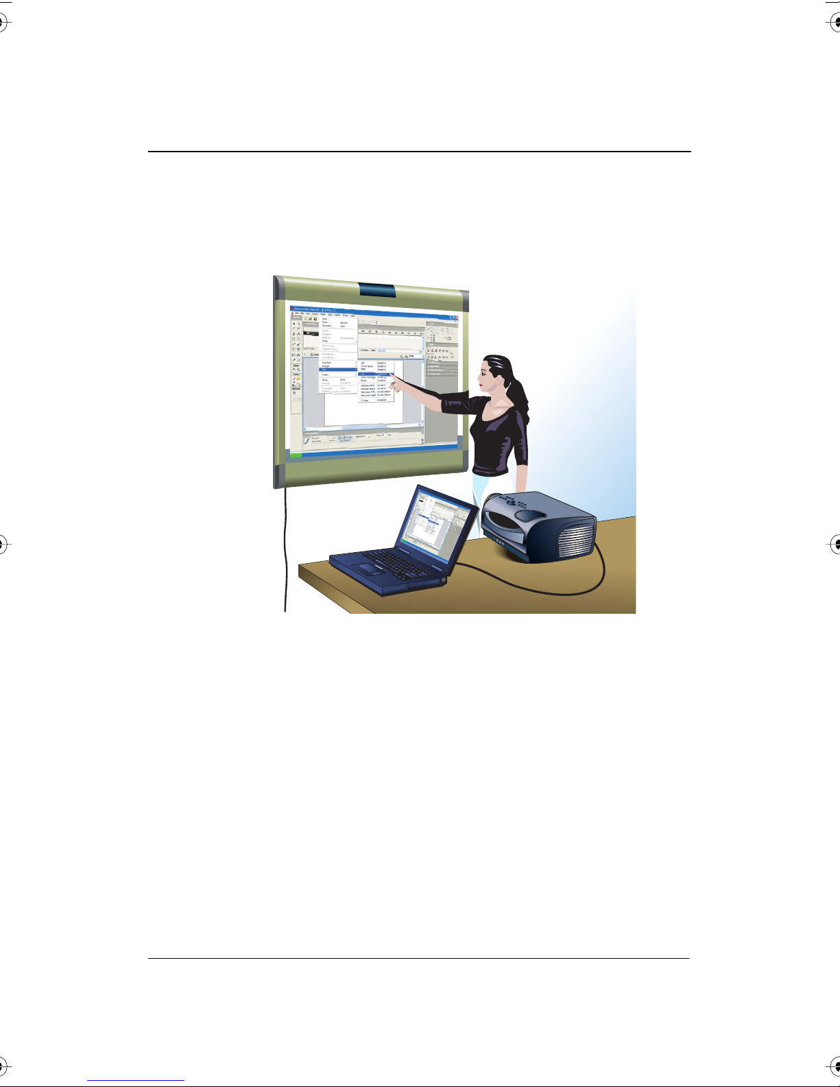
Congratulations on your purchase of a PolyVision® Walk-and-Talk™ (WT),
Walk-and-Talk Lightning, (WTL), TS, or TS Lightning (TSL) interactive
whiteboard.
This manual describes how to install and use PolyVision interactive
whiteboards. For more information about using these interactive
whiteboards, refer to the
computer with the PolyVision driver.
To view the user guide in Windows:
• Click “Start” in the lower left corner of your desktop, choose
“Programs,” then “PolyVision,” then "PolyVision driver," and then
“PolyVision User Guide.”
To view the user guide on a Macintosh:
• Navigate to the “Applications” folder on your start-up disk, and
double-click “PolyVision User Guide” in the PolyVision folder.
Overview 3
PolyVision User Guide which is installed on your
®
PolyVision

Options and Considerations
This manual describes how to install your PolyVision interactive whiteboard
and get started using it.
These options are available for mounting the PolyVision interactive
whiteboards, depending on your model.
• You can mount any PolyVision interactive whiteboard on a mobile
stand available from your PolyVision dealer. If you use this option,
follow the mounting instructions provided with the mobile stand, then
proceed to “PolyVision Driver Installation (WT Models)” on page 10
(Walk-and-Talk models) or “PolyVision Driver Installation (TS Models)”
on page 19.
• You can mount any PolyVision interactive whiteboard to a sheetrock,
brick, cinder block, plaster, or metal wall using the instructions
provided here.
• You can mount Walk-and-Talk models to the Walk-and-Talk Power
and Data Track System, a track system that enables the whiteboard
to slide over an existing whiteboard or a blank wall.
Before using your PolyVision interactive whiteboard, first install the
PolyVision driver on your computer. Refer to “PolyVision Driver Installation
(WT Models)” on page 10 or “PolyVision Driver Installation (TS Models)” on
page 19.
®
PolyVision
Register Your PolyVision Whiteboard
By registering your product, your warranty is automatically extended by
three years and you will receive enhanced customer service with
information on software upgrades.
To register your PolyVision product:
• Register on-line at:
www.polyvision.com/support/register.asp
4 Installation and Operation Guide
Installing Your Walk-and-Talk Whiteboard
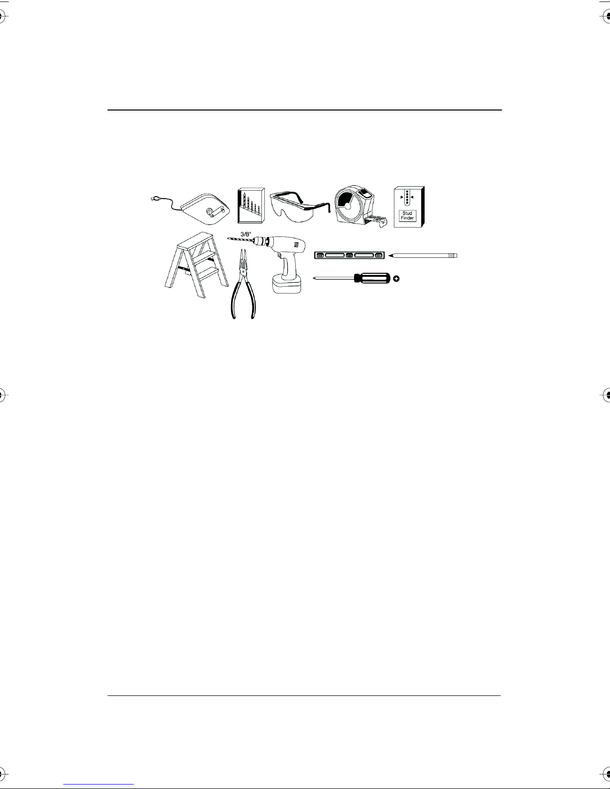
Each board weighs 77 to 102 pounds (35 to 46 kg). Plan your installation
work accordingly. Two people are needed for portions of this installation.
You will need to provide these tools:
Installing Your Walk-and-Talk Whiteboard 5
®
PolyVision
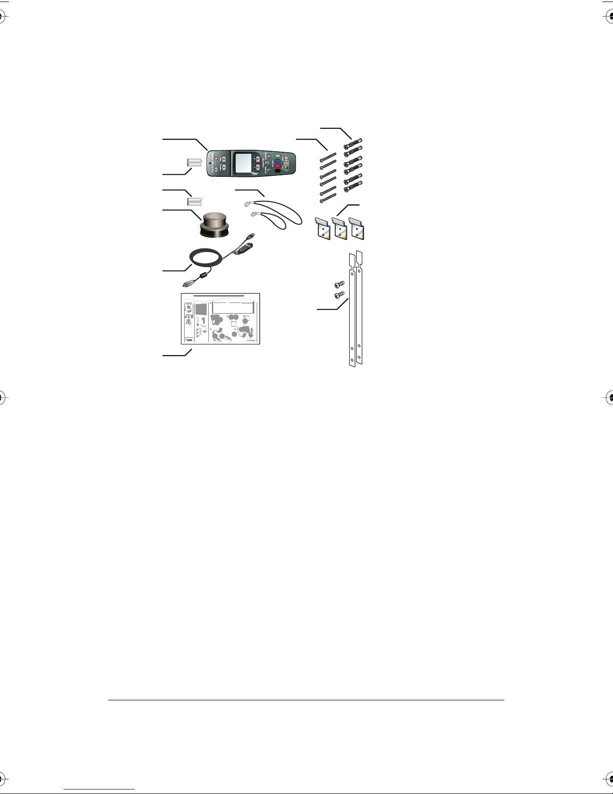
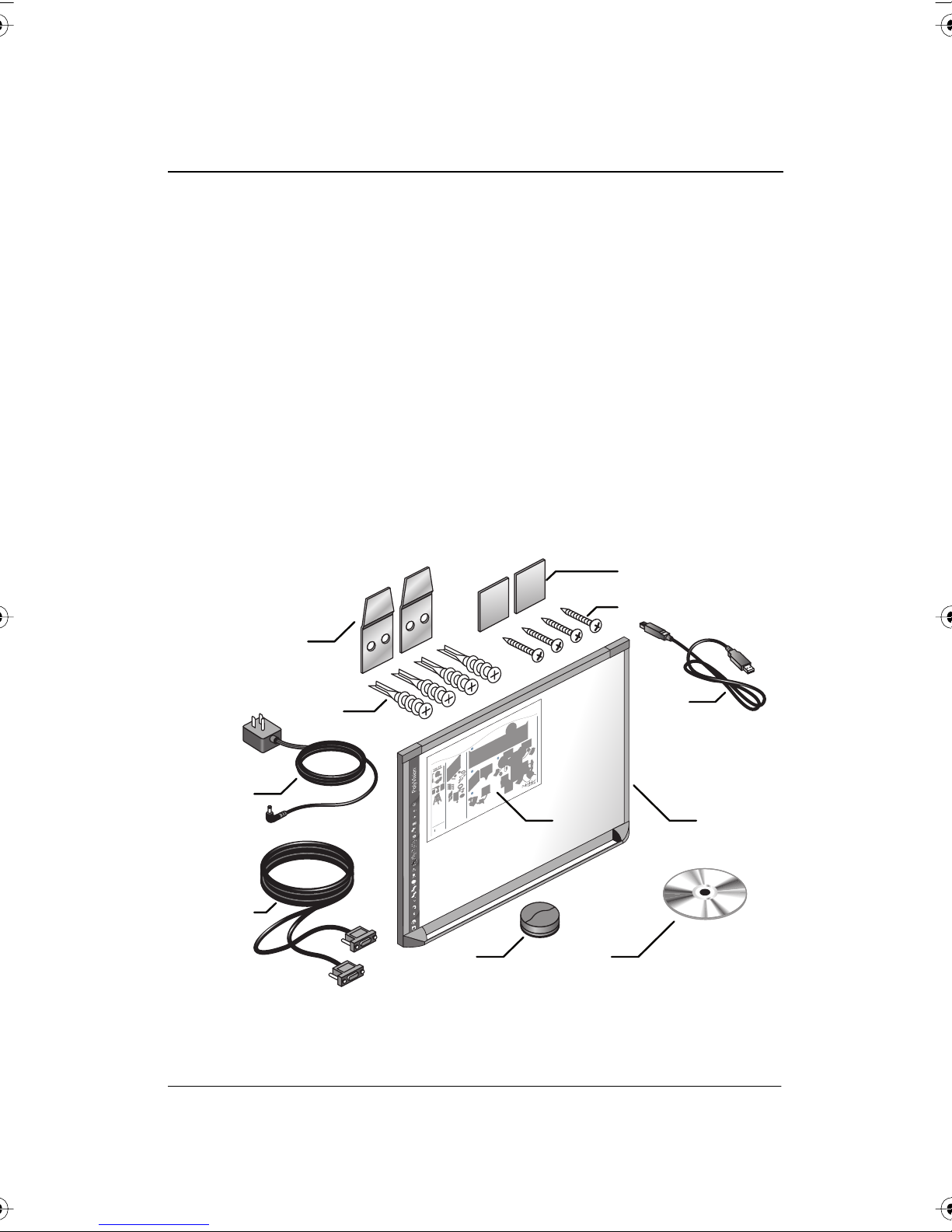
What Comes in the Box
1 8
2
3
7
4
5
Quickstart Installation Guide
18XX
14XX
16XX
1
#2
3/8"
T
e
chn
P
l
u
I
g
o
n
l
s
o
a
t
nd
g
a
y
nt
P
l
a
y
P
o
ly
K
e
y
T
M
5
ab
4 32
6
6
9
10
11
®
PolyVision
1 remote control
2 remote control batteries (AAA)
3 eraser batteries (AAA)
4 eraser
5 USB cable with PolyKey for driver installation
6 Installation Quick Start
7 two remote control lanyards: one wrist-sized, one neck-sized
8 six (16xx models) or eight (18xx models) screws
9 six (16xx models) or eight (18xx models) sheet rock anchors
10 three (16xx models) or four (18xx models) wall brackets
11 two safety straps and screws
Preparing to Mount the Whiteboard
These instructions guide you through installing your interactive whiteboard
on a sheetrock wall. If your wall material is some other substance, such as
concrete or brick, use these instructions as a guideline but install
appropriate anchors to secure the unit to the wall.
6 Installation and Operation Guide

note:NOTE:
Locate and have ready to use:
• tape measure
• phillips screwdriver
• drill
• level
• safety glasses
• pencil
• stud finder
• step stool
• models WT or WTL 16xx: three wall brackets and six sheetrock
anchors with screws
• models WT or WTL18xx: four wall brackets and eight sheetrock
anchors with screws
• safety straps and screws
Instructions and fasteners are provided to help you install the whiteboard
when walls have metal or wood studs. Be sure to locate wall studs and use
them to drive mounting screws whenever possible.
To position the wall brackets:
1 Choose a location on the wall with convenient access to your
computer, an AC power outlet, and a projector or network connection,
as appropriate.
2 Where possible, locate wall studs and select drill hole locations that
align with wall studs. Sheetrock anchors are provided in case studs
cannot be used.
Installing Your Walk-and-Talk Whiteboard 7
®
PolyVision
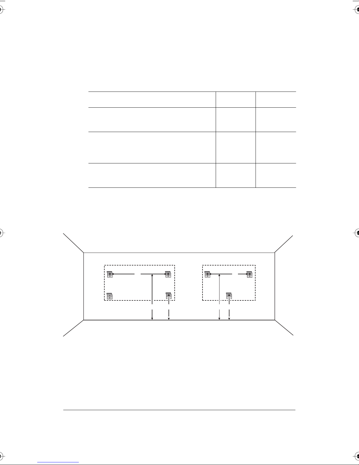
3 Carefully mark three (WT or WTL16xx) or four (WT or WTL 18xx) drill
hole locations as indicated in the table and illustration below, based on
your Walk-and-Talk model. Measurements are for a standard (adult)
height whiteboard*:
Model 16xx 18xx
A: Distance from floor to top holes in upper
brackets*
B: Distance between holes
C: Distance from floor to top holes in lower
brackets*
75"
1905 mm
48"
1219 mm
36.25"
920 mm
75"
1905 mm
72" or 80"**
1823 mm or
2032 mm
36.25"
920 mm
*To enable access for young children, reduce vertical measurements by
6 inches (152 mm).
**Choose either 72" or 80" (1823 mm or 2032 mm), whichever distance
enables you to fasten the wall bracket to a wall stud.
18xx 16xx
B
B
®
4 Using a wall bracket as a template, mark the screw hole locations for
each wall bracket.
5 If installing in sheetrock, install six (WT or WTL 16xx) or eight (WT or
WTL 18xx) sheetrock anchors in the wall at the marked hole locations.
PolyVision
8 Installation and Operation Guide
A A CC
If installing on some other substance such as concrete or brick, use
appropriate anchors.
Mounting the Whiteboard
To mount the wall brackets:
1 Fasten the two top wall brackets to the wall anchors with a safety
strap sandwiched between the wall bracket and the wall.
2 Fasten the bottom wall bracket(s) to the wall.
3 Ensure that the screws are snug.
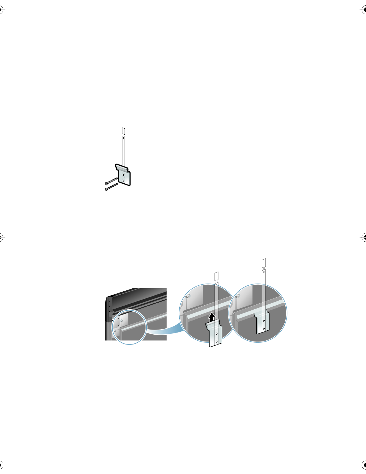
To mount the whiteboard:
1 With the help of an assistant, lift the whiteboard and hang it on the wall
brackets.
2 Slide the whiteboard carefully to align the safety straps with the holes
in the top of the whiteboard.
®
PolyVision
Installing Your Walk-and-Talk Whiteboard 9
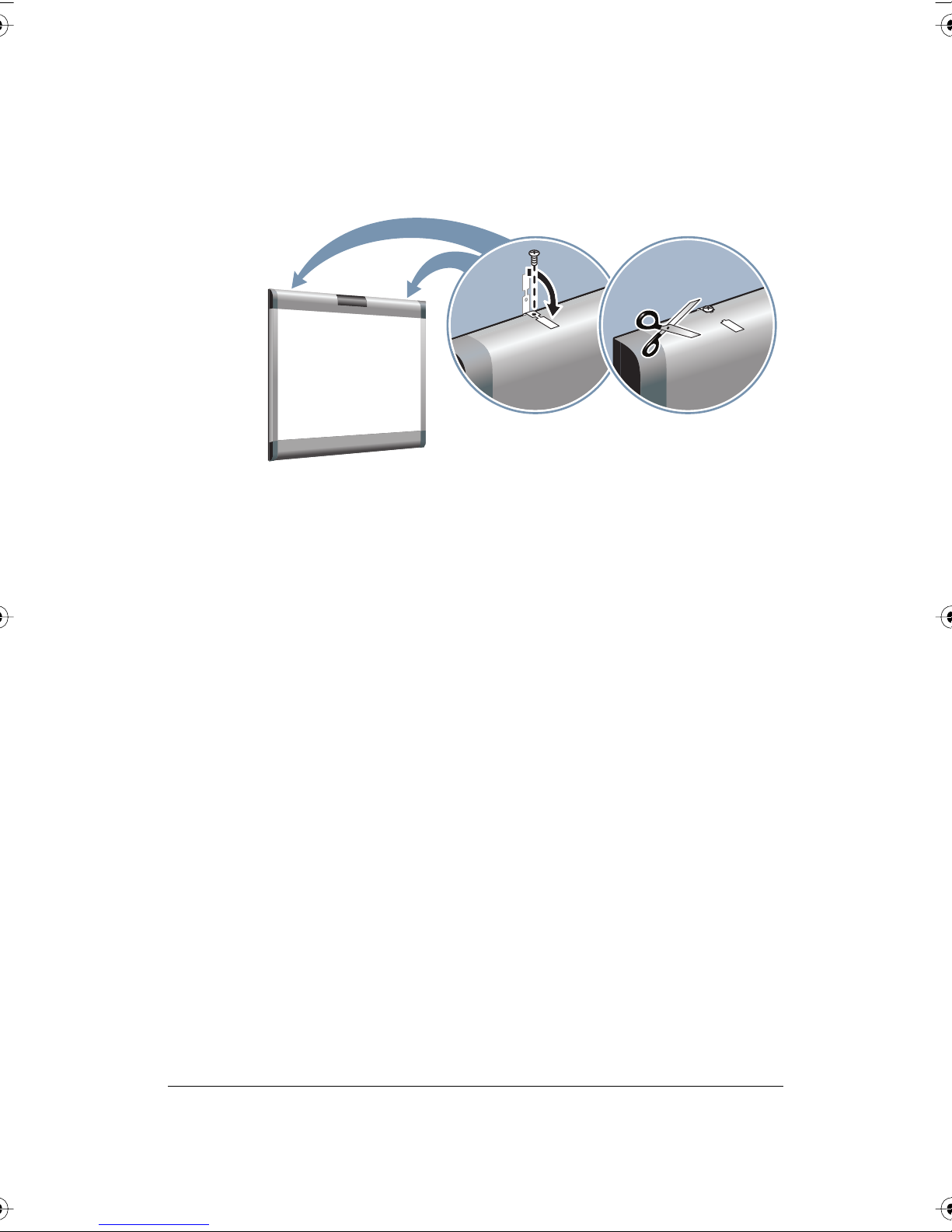
3 Fold over and fasten the two safety straps to the whiteboard using the
screws provided.
4 Using scissors, snip off the safety straps’ finger tabs.
PolyVision Driver Installation (WT Models)
®
PolyVision
System Requirements
Your Windows-based computer must have:
• Windows 2000, XP, Tablet XP, or Vista
• VGA HD-15 video port
• USB port
Your Macintosh computer must have:
• PowerPC G3 or higher or Intel-based processor
• Mac OS X 10.2 or higher
• VGA HD-15 video port
• USB port
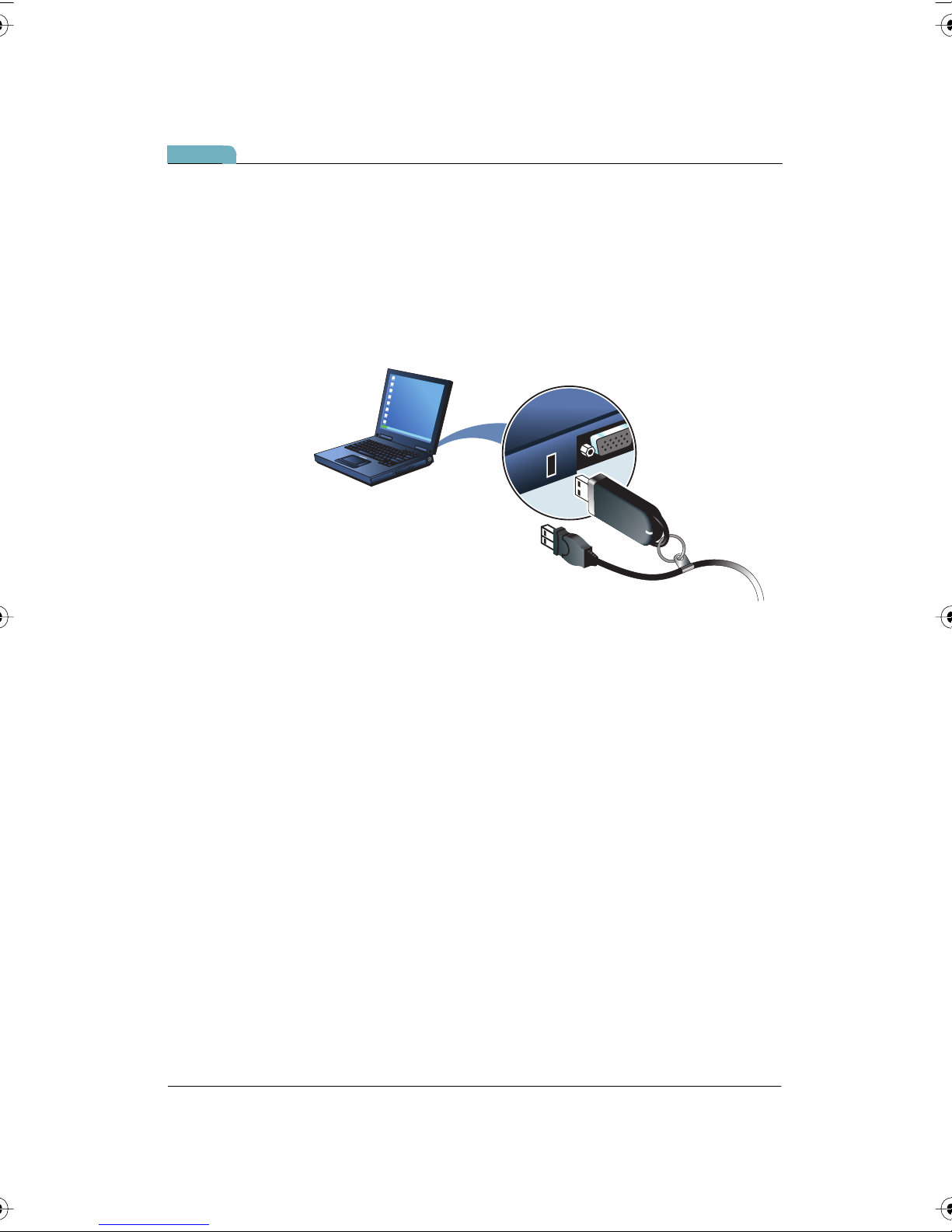
Driver Installation for Walk-and-Talk Models
The PolyVision driver is always close at hand. You need no installation disk
or CD-ROM. Driver installation takes place when you connect the PolyKey
on the Walk-and-Talk USB cable to your computer’s USB port.
10 Installation and Operation Guide
note:NOTE:
The Power/Status LED on the lower left corner of the WT board glows solid
yellow until the PolyVision driver on your computer is communicating with
the board, then it turns green. Refer to “LED and Status Messages on the
Walk-and-Talk Whiteboard” on page 12.
To install the PolyVision driver on your computer:
1 Locate the Walk-and-Talk USB cable.
2 Connect the PolyKey on the USB cable to your computer’s USB port.
3 Installation should begin automatically. If it does not:
Windows: double-click “My Computer” on your desktop and double-
click the removable disk named “PolyKey.” Installation begins.
Macintosh: double-click the PolyKey icon on your desktop, double-
click the “Macintosh” folder, and double-click “the PolyVision driver
Installer.” Installation begins.
4 Follow the prompts you see on the screen to complete the installation.
On a Macintosh, your system automatically reboots.
When installation is complete, a message appears on your computer
screen and the PolyVision driver icon appears in your system tray
®
PolyVision
Installing Your Walk-and-Talk Whiteboard 11
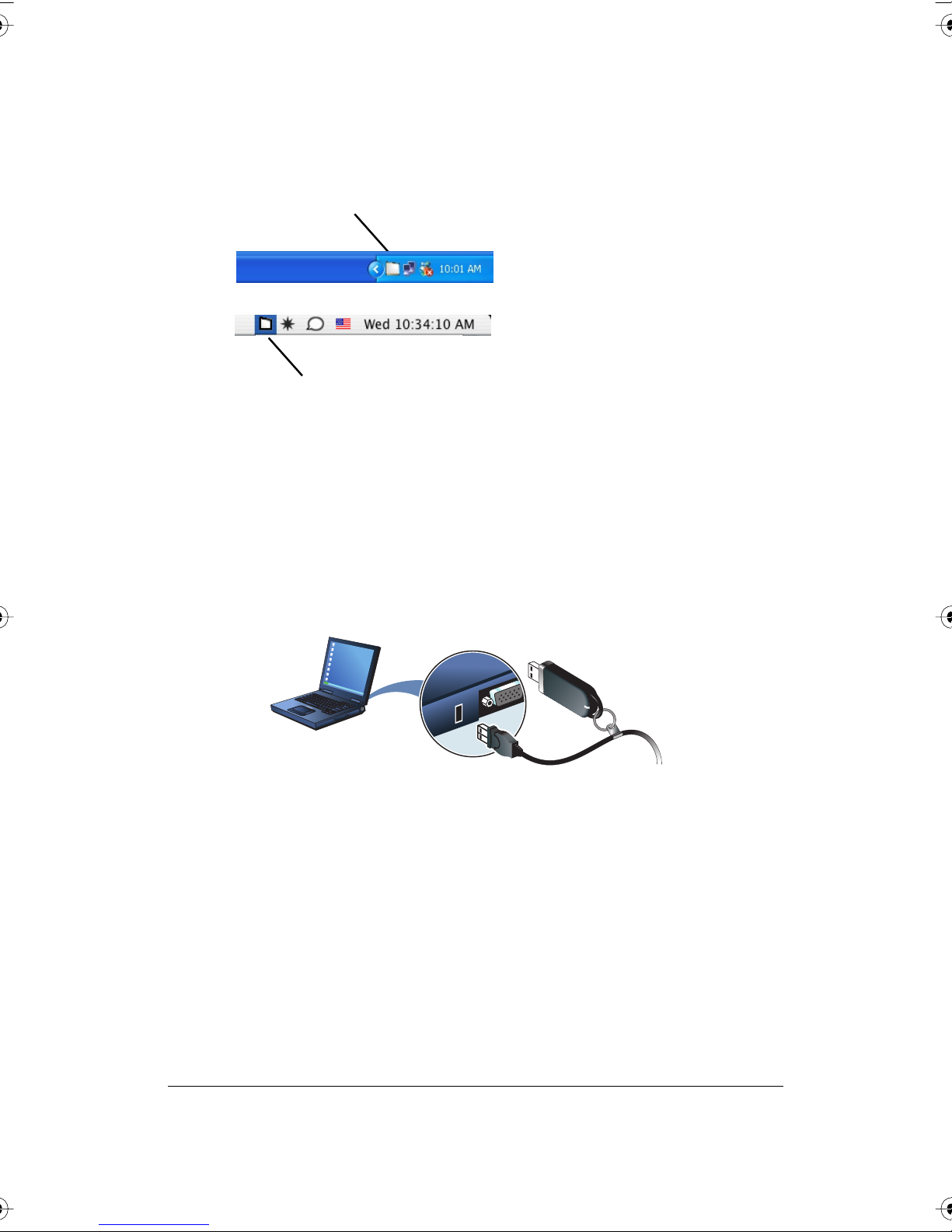
(Windows) or system menu (Macintosh). For more information about
operating your whiteboard, refer to the
PolyVision driver icon
PolyVision driver icon
To start using the PolyVision driver and interactive whiteboard:
1 Windows: disconnect the PolyKey.
Macintosh: drag the PolyKey icon to the Trash or choose “Eject” from
the File menu, then disconnect the PolyKey.
2 Connect the USB cable to your computer’s USB port and the other
cable end to your interactive whiteboard. The whiteboard’s Power/
Status LED should turn green. If it remains yellow, the driver is not
properly installed.
PolyVision User Guide.
system tray (Windows)
system menu bar (Macintosh)
®
The PolyVision driver runs unobtrusively in the background whenever your
computer is on and connected to the interactive whiteboard via the USB
cable.
LED and Status Messages on the Walk-and-Talk Whiteboard
Your Walk-and-Talk whiteboard provides both LED and audible feedback to
PolyVision
12 Installation and Operation Guide
indicate the status of your system.
note:NOTE:
WT and WTL whiteboards obtain power and data through the USB
connection to your computer. If you are using the BT wireless option, refer
to “Installing the Wireless BT Option” on page 39.
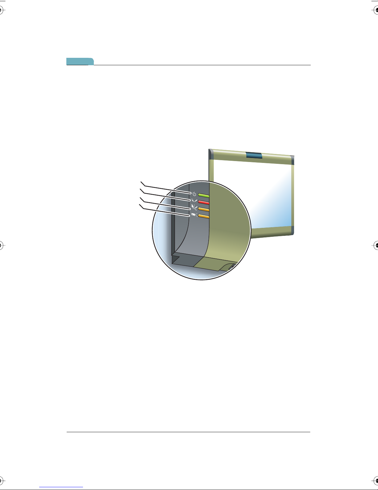
LED Status Indicators
LED indicators on the lower left edge of the board provide information
about the status of the board.
Power/Status
Ink Recorded
Pen Mode Active
Projection
Installing Your Walk-and-Talk Whiteboard 13
®
PolyVision

The table below explains the Power/Status LED indications.
Power/Status LED Meaning
Off No power to the board.
Solid yellow Hardware is working, but the PolyVision driver is not
communicating.
Blinking yellow Processing a command.
Green Ready to use.
Hardware is working, communicating with the PolyVision
driver.
Red Hardware problem.
The table below explains the Ink Recorded LED indications.
Ink Recorded LED Meaning
Off The PolyVision driver believes there is no dry-erase ink on
the whiteboard.
Red The PolyVision driver believes there is dry-erase ink on
the board. Press the Erase All button on the remote
control if this LED is red and there is no dry-erase ink on
the board.
®
PolyVision
The table below explains the Pen Mode Active LED indications.
Pen Mode Active
LED
Off The Walk-and-Talk whiteboard is not in projection mode,
or while in projection mode, the cursor is active. Tap on
the board to move the computer’s mouse cursor.
Yellow The board is in pen mode. Use a finger to draw on top of
the projected image.
Meaning
14 Installation and Operation Guide

The table below explains the Projection Mode Active LED indications.
Projection Mode
Active LED
Off The Walk-and-Talk whiteboard is capturing dry-
erase ink over the entire surface of the board and is
not controlling the computer.
Yellow The Walk-and-Talk whiteboard is controlling the
computer where the image is projected and
capturing dry-erase ink elsewhere.
Blinking yellow Projection alignment is needed. Press the Projection
button on the remote control to re-align the image.
Meaning
Sounds
While you use your whiteboard, sounds indicate the status of the system.
You can disable or enable sounds; refer to the on-line
Guide
for information about sounds and other driver options.
The following sounds indicate the whiteboard status:
Sound Condition
Fanfare Software launch or power on
Polyvision User
Flop Software exit or critical hardware errors
Click Alignment point tapped or remote button pressed
Installing Your Walk-and-Talk Whiteboard 15
®
PolyVision
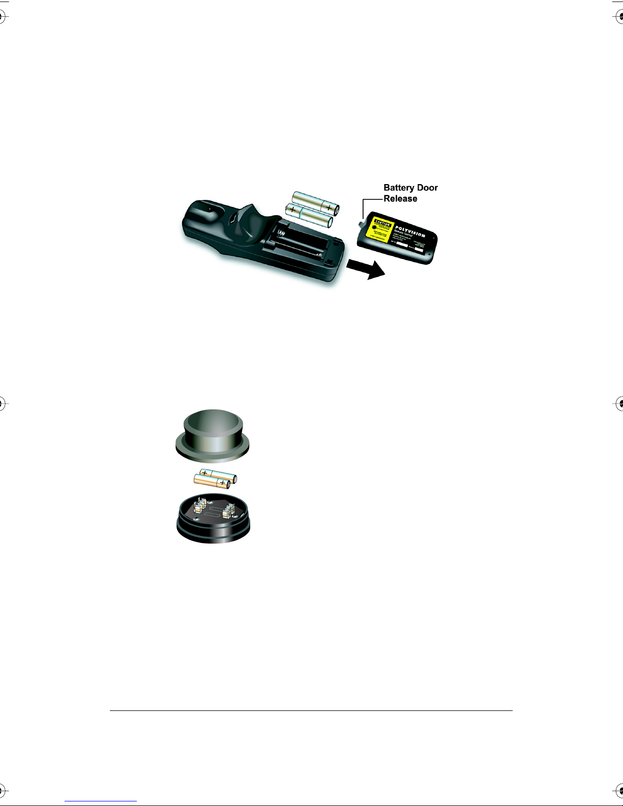
Adding Batteries to the Walk-and-Talk Remote
The Walk-and-Talk infrared remote control uses two AA batteries
(provided).
To add batteries:
• Press down and pull back to release the battery compartment door.
Adding Batteries to the Walk-and-Talk Eraser
The Walk-and-Talk eraser uses two AAA batteries (provided).
To add batteries:
1 Gently peel back the soft eraser handle to expose the battery
compartment.
®
2 Insert the batteries as marked. Make sure that you place the batteries
in with the positive terminals on the positive (+) side.
PolyVision
16 Installation and Operation Guide
Installing the TS or TSL Whiteboard
To mount your whiteboard on an optional mobile stand, see the instructions
included with your mobile stand or visit www.polyvision.com.
What Comes in the Box (TS or TSL Models)
1 1 whiteboard
2 1 peel-off quick start
3 1 serial port cable (TS 600 models)
4 1 AC power cord (TS 600)
5 4 self-tapping sheet rock anchors
6 4 Phillips screws
7 2 mounting brackets
8 2 Velcro strips
9 1 USB cable (TS 610 or 810 and all TSL models)
10 1 round eraser
11 1 software CD (Mac/Windows)
8
4
3
7
5
ojection
r
P
vious
e
r
P
Next
d
r
Keyboa
en / Cursor
P
en Style
P
en
P
Red
en
P
Blue
n
e
P
en
e
r
G
en
P
Black
en
P
ow
r
Nar
en
P
Medium
en
P
de
Wi
en
P
Solid
en
P
Dashed
aser
r
Small E
aser
r
Large E
ase All
r
E
rint
P
e
v
Sa
PolyVision TS and TS Lightning Interactive Whiteboard
PolyVision TS Lightning Interactive Whiteboard
Quickstart Installation Guide
8
9
3
2
10
5
8
/
3
4
6
12
7
11
1 whiteboard
1
1 whiteboard stylus
2
1 round eraser
3
L
4 self-tapping sheet rock anchors (varies by model)
4
4 Phillips screws
5
2 mounting brackets
6
2 Velcro strips
7
1 AC power cord (TS400, 600, or 800 models)
8
1 USB cable (TS 410, 610 or 810 and all TS
9
models)
1 serial port cable (TS400, 600, or 800 models)
10
1 user guide
11
1 Webster software CD (Mac/Windows)
12
Y
1 peel-off quick start
L
O
13
800.620.P
678.542.3100
+32.089.32.31.30
TM TM
1
2
4
6
0140-00
N 580P
3
5
2
9
1
®
1110
PolyVision
Installing the TS or TSL Whiteboard 17

Mounting on the Wall
You will need a tape measure, Phillips screwdriver, and drill.
To mount any TS or TSL whiteboard on a wall:
1 Choose a location with convenient access to your computer, an AC
power outlet, and any network connections or projectors you are
using.
2 Carefully mark two drill hole locations as indicated below, based on
your TS whiteboard model:
TS/TSL 8XX TS/TSL 6XX
®
92"
(2335 mm)
77" (1950 mm)
Model
TS or TSL
600/610
TS or TSL
800/810
3 Using the mounting plates as a template, mark two additional drill hole
locations that are 3/4
4 For sheet rock walls, screw the self-tapping sheet rock anchors into
note:NOTE:
the wall using a power driver, if available.
Distance from the floor to the
holes
77"
(1950 mm)
77"
(1950 mm)
" (19 mm) from the original hole.
62"
(1575 mm)
77" (1950 mm)
Distance between hole
locations
62"
(1575 mm)
92"
(2335 mm)
If you are not installing on a sheet rock wall, you must provide your own
fasteners.
5 Attach the mounting bracket to the wall anchors on the wall using the
four Phillips screws provided. Assure that the screws are snug.
PolyVision
18 Installation and Operation Guide

6 With the help of an assistant, lift the board and hang it on the
mounting plates using the slots at the top corners of the board.
7 Peel the backing off the front and back of the two Velcro strips.
8 Attach Velcro strips to lower right and left corners on the back of
whiteboard and press against the wall.
PolyVision Driver Installation (TS Models)
System Requirements
Your Windows-based computer must have:
• Windows 2000, XP, Tablet XP, or Vista
• VGA HD-15 video port
• USB port
Your Macintosh computer must have:
• PowerPC G3 or higher or Intel-based processor
• Mac OS X 10.2 or higher
• VGA HD-15 video port
• USB port
®
PolyVision
Installing the TS or TSL Whiteboard 19

Driver Installation for TS Models
To install the PolyVision driver:
1 Locate the installation CD provided with your whiteboard.
2 Insert the CD into your computer disk drive.
3 Installation should begin automatically. If it does not:
Windows: double-click “My Computer” on your desktop, double-click
the disk named “PolyVision driver,” double-click the Windows folder,
and double-click “PolyVision driver installation.” Installation begins.
Macintosh: double-click the PolyVision driver icon on your desktop,
double-click the Macintosh folder, and double-click “PolyVision driver
installation.” Installation begins.
4 Follow the prompts you see on the screen to complete the installation.
On a Macintosh, you must re-boot your system.
When installation is complete, a message appears on your computer
screen and the PolyVision icon appears in your system tray (Windows) or
system menu (Macintosh). For more information about operating your
whiteboard, refer to the
PolyVision User Guide.
Connect Power and Data for TS or TSL Models
®
PolyVision
After you install the PolyVision driver on your computer, connect the
whiteboard and computer. Ensure that both your computer and whiteboard
are powered off before you make connections.
note:NOTE:
If you are using the wireless option, refer to “Installing the Wireless BT
Option” on page 39.
Connections for all TSL and TS 610 or 810 Models
To connect the whiteboard to your computer:
1 Plug the USB cable to the USB port on your computer.
20 Installation and Operation Guide

2 Plug the other end of the USB cable to the USB port on the
whiteboard.
Connections for TS 600 Model
To connect the whiteboard to your computer:
1 Plug the AC power cord into the power connector on the bottom of
the whiteboard, next to the serial port.
9-Pin Serial Cable
AC Power Cord
®
PolyVision
Installing the TS or TSL Whiteboard 21

note:NOTE:
2 Plug the power cord into an electrical outlet.
3 Plug the 9-pin male end of the serial port cable into the whiteboard
and tighten the screws.
4 Plug the other end into your computer’s serial port (if necessary, use a
USB to 9-pin serial adapter available from your PolyVision dealer).
The maximum serial port cable length is 25 feet (7.5 meters). For greater
distances, a serial amplifier is required (available at computer networking
suppliers).
®
PolyVision
22 Installation and Operation Guide

Using Your PolyVision Interactive Whiteboard
Using Dry-Erase Markers with Your Board
Your PolyVision whiteboard senses writing and erasing that you can print or
save by detecting pressure.
• Use only the eraser provided with your whiteboard.
• Use firm consistent pressure.
• Make sure there is only one point of contact at a time.
note:NOTE:
The whiteboard surface can be damaged by sharp objects such as
ballpoint pens and rulers.
To write on the board so it can be saved or printed:
1 Choose a dry-erase marker.
2 Press an ink color button on the remote control (Walk-and-Talk
models) or tap a pen color icon on the whiteboard (TS models)
corresponding to the marker color.
3 Write on the board.
When you write on the board:
• Walk-and-Talk models: the red “Ink Recorded” LED glows to indicate
that the computer has detected your writing. Refer to “LED and Status
Messages on the Walk-and-Talk Whiteboard” on page 12.
• TS models: the whiteboard provides audible feedback and the green
LED glows brighter to indicate that it recognizes your strokes.
You can print or save your notes as a digital image on your computer. To
save your writing:
• Press the Print or Save button on the remote control (Walk-and-Talk
models) or tap the Print or Save icon on the whiteboard (TS models).
A snapshot of the writing is saved on your computer.
To erase so it is recorded:
• Walk-and-Talk models: erase using the large circular felt eraser
provided. The battery-operated eraser sends infrared data to the
computer through the whiteboard.
®
PolyVision
Using Your PolyVision Interactive Whiteboard 23

• TS models: tap the Large or Small Eraser icon on the board and erase
using the circular felt eraser provided, or using your finger for small
erasures.
• To erase everything and start fresh, press the Erase All button on the
remote control (Walk-and-Talk models) or tap the Erase All icon on the
whiteboard (TS models).
Projecting Your Computer onto the Whiteboard
When you use the PolyVision interactive whiteboard with a projector
connected to your computer, a variety of powerful options becomes
available. You can:
• Control your computer from the whiteboard. For Walk-and -Talk
products, you can also roam freely about the room and interact with
the computer using the remote control.
• Run slide presentations and other software.
• Make notes and drawings over your computer’s projected screen that
you can print or save.
®
PolyVision
24 Installation and Operation Guide

Getting Started with Your Projector
Cable connections between your computer, the board, and the projector
enable you to control your computer from the Walk-and-Talk whiteboard.
Getting started is simply a matter of connecting your projector to your
computer using the video cable that is provided with your projector.
To set up the projector:
1 Locate your projector’s video cable and connect it to the video port of
your computer.
2 Connect the other end of the video cable to your projector.
3 Connect the projector’s power cord to an outlet.
4 Turn on the projector and focus your computer screen squarely onto
your whiteboard. The projected image does not need to fill the white
area.
To align the projected image with a Lightning (TSL or WTL) whiteboard:
1 Assure that at least half of the projected image is actually projected
onto the board.
2 Press the Projection button on the remote control (WTL models) or tap
the Projection icon on the whiteboard (TSL models) one time.
Using Your PolyVision Interactive Whiteboard 25
®
PolyVision

To align the projected image with WT or TS models:
1 Move the projector physically so that the entire solid-colored
background is positioned inside the borders of the whiteboard.
2 Press the Projection button on the remote control (Walk-and-Talk
models) or tap the Projection icon on the whiteboard (TS models). The
following alignment window projects from the computer to the board.
3 Using your finger, tap the board exactly on each target, following
instructions you see on the board.
®
PolyVision
When alignment is complete, you are ready to begin using your computer
and whiteboard in projection mode.
To exit projection mode when you are finished operating your computer
from the board:
• Press the Projection button on the remote control (Walk-and-Talk
models) or tap the Projection icon on the whiteboard (TS models).
Cursor Control in Projection Mode
PolyVision products display your projected computer image and enable
you to control your computer using:
• your finger
• the remote control (Walk-and-Talk models)
When you want to control your computer, always touch the whiteboard
inside the borders of the projected computer image:
• To click, tap the display once.
26 Installation and Operation Guide

• To double-click, tap the display twice rapidly.
• For a right-click (Windows) or control-click (Macintosh), hold your
finger to the display for one second.
• To page up or down through a document, press the “Next” or
“Previous” button on the remote control (Walk-and-Talk models) or the
“Next” or “Previous” icon on the board (TS models).
Walk-and-Talk models: you can roam freely about the room and control the
projected computer screen using the remote control. To operate your
computer with the remote control, point it toward the infrared receiver on
the whiteboard:
• To click or double-click, press the “L” button or the click trigger once
or twice, or tap once or twice on the remote control touch pad.
• For a right-click (Windows) or control-click (Macintosh), press the “R”
button.
Marking-Up Your Projected Computer Desktop
While your computer desktop is projected on the interactive whiteboard,
the PolyVision driver enables you to draw, highlight, and write over the
projected image using your finger. This type of writing is called “mark-up”
and it is part of the projected image, not physical ink.
To mark-up the projected computer image:
1 Press the Cursor/Pen button on the remote control (Walk-and-Talk
models) or tap the Pen Cursor icon on the whiteboard (TS models) to
toggle between writing with the pen or controlling the computer
mouse. The cursor changes from an arrow to a pen.
2 Write over the projected computer image on the board using your
finger.
Writing Notes Next to a Projected Image
While in projection mode, you can also use a dry-erase marker to write
notes on the board beside the projected image from your computer.
Snapshots include everything you see, including any writing, the computer
projection, and mark-ups.
®
PolyVision
Using Your PolyVision Interactive Whiteboard 27

Using the Walk-and-Talk Remote Control
The Walk-and-Talk remote control operates at a distance of up to 40 feet
(12 m) from the infrared receiver, enabling you to roam freely away from
your computer while you give your presentation.
Always point the remote control toward the infrared receiver at the top of
the interactive whiteboard.
Remote Control Options
The remote control functions equally well in various locations.
• Carry the remote control with you using the wrist or neck lanyard
provided.
• Place the remote control near you on a desk or table top pointed
toward the infrared receiver.
®
PolyVision
28 Installation and Operation Guide

Remote Control Functions
Using Your PolyVision Interactive Whiteboard 29
®
PolyVision

Erase All
r
Previous
Projection
Next
L R
Projection
When a projector is connected
to your computer and focused on
the board, press this button to
enter projection mode so you can
control the computer from the board.
Next
When the cursor is active, press this
button to page down or move to
the next slide or web page.
When the pen is active, this button
returns to the computer mark-up screen.
Previous
When the cursor is active, press this
button to page up or move
to the previous slide or web page.
When the pen is active, press this button
to display a blank mark-up screen.
Touch pad
In projection mode, use the touch pad
to control your computer cursor just as
you would on a laptop computer
touch pad. Tap once to click and twice
to double-click. Always use the tip of you
thumb or your forefinger. Never use the
flat of your thumb.
®
PolyVision
Click trigger
YES
L and R
In projection mode, press L for
a left mouse click and R for a
right mouse click (Windows) or
control click (Macintosh). You
can also use the click trigger on
the bottom of the remote
control for a left mouse click or
double-click.
NO
30 Installation and Operation Guide

Using Your PolyVision Interactive Whiteboard 31
®
PolyVision

Using the TS Icon Strip
The TS and TSL Interactive Whiteboards include a touch-sensitive icon
strip along the edge of the board that provides the same functions as the
Walk-and-Talk remote control.
®
PolyVision
32 Installation and Operation Guide

TS Icon Operation
Togg les “projection mode” on and off. The first use starts the onscreen
alignment (calibration) process.
Goes to the previous PowerPoint slide or PgUp.
Goes to the next PowerPoint slide or PgDown.
Displays the on-screen keyboard.
Toggles between writing and cursor control.
Displays all pen size and color options.
The current pen color for writing on the board.
The current pen width.
Sets the pen to a solid line.
Sets the pen to a dashed line.
Small eraser width using the pen.
Large eraser width using the pen.
Clears all the writing.
Prints a copy of the whiteboard.
Saves a copy of the whiteboard.
Using Your PolyVision Interactive Whiteboard 33
®
PolyVision

Care and Maintenance
Replacing the Walk-and-Talk Eraser Pad
To replace eraser pads:
1 Peel off the old eraser pad.
2 Remove backing from the self-adhesive replacement pad.
3 Position the replacement pad over the eraser and press firmly.
Cleaning the Walk-and-Talk WhiteBoard
®
PolyVision
We recommend an initial cleaning of the board to remove any residue left
behind during manufacture.
1 For the initial cleaning, wipe your board with a clean cloth moistened
by a commercially available whiteboard cleaner.
2 Rinse with clear water to avoid future smearing. This step is simple but
very important.
3 Wipe dry with a clean cloth.
note:NOTE:
Do not let water seep into the sensitive Walk-and-Talk whiteboard
electronics. Your warranty does not cover damage caused by liquids.
Caring for the TS or TSL Whiteboard
Your whiteboard can have one of two possible surfaces. The appropriate
care of each surface is very different. To determine which whiteboard
surface you have, find the serial number located on the underside of the
whiteboard tray next to the power connection.
34 Installation and Operation Guide

Use the care instructions below if your board’s serial number begins with
“A” or “B”:
• Wipe the whiteboard with a clean, soft, dry cloth or a duster.
• Clean whiteboard parts with a cloth dampened with mild soap and
water. Stubborn stains can be removed using isopropyl alcohol.
• Do not use spray cleaners (such as whiteboard cleaner). Spray cleaners
will damage the board.
• Do not use abrasive cleaners or cloths.
Use the care instructions below if your board’s serial number begins with
any other letter:
• For daily cleaning or as needed, rinse surfaces with water using a soft
cloth or sponge. Dry with a soft cloth prior to writing.
• Remove any remaining marks with Sanford Expo Towelettes or
equivalent. Whiteboard cleaners available from PolyVision or at office
supply stores can also be used.
• Important! Always rinse with water and dry with a soft cloth to prevent
future markers from smearing.
• For stubborn stains, you can use a paint/stain remover such as Goof
For all TS and TSL whiteboards:
• Use only the dry-erase markers and erasers recommended by
• Change erasers when they become dirty to leave less ink residue on
• Do not use ballpoint pens or other pointed instruments on the surface.
• Do not use abrasive cleaners on the surface.
• To erase pen strokes made with permanent markers, write over the
®
Off
. After the stain has been removed, rinse with clean water and dry
with a soft cloth.
PolyVision. To order markers, call 1.800.620.POLY (7659) in the USA,
1.678.542.3100 outside the USA, or +32 (0)89 32 31 30 in Europe, or
go to:
• www.polyvision.com
your board. Replacement erasers are available directly from PolyVision.
Call 1.800.620.POLY (7659) in the USA, 1.678.542.3100 outside the
USA, or +32 (0)89 32 31 30 in Europe, or go to:
• www.polyvision.com
marks with a dry-erase marker of the same or similar color, then erase.
®
PolyVision
Care and Maintenance 35

• To avoid damage, use only the power supply or cord that came with
your whiteboard.
• To store your whiteboard for prolonged periods, place it in a vertical
position. Do not store flat.
• Keep all shipping cartons in case you need to return your board for
repair.
Caring for the Markers and Eraser
• Cover the markers when not in use.
• Store the markers horizontally.
• Rub the eraser against a towel to remove ink residues. If excessive ink
buildup occurs, contact PolyVision for a replacement. Call
1.800.620.POLY (7659) in the USA, 1.678.542.3100 outside the USA,
or +32 (0)89 32 31 30 in Europe, or go to:
• www.polyvision.com
How to Obtain Replacement Parts
Replacement parts are available directly from PolyVision. Call
1.800.620.POLY (7659) in the USA, 678.542.3100 from elsewhere in North
America, or +32 (0)89 32 31 30 in Europe. You can also send e-mail to
info@polyvision.com.
®
PolyVision
Summer Maintenance
• Gather all items that are loose and can be easily disconnected from
the board and/or computer. Store all items in a safe and secure place.
(For example, the USB cable, wireless receivers, USB hubs, stylus,
and eraser.)
• Tape a sign to top frame of board to say:
• This board is not a markerboard.
• Do not wash the board. Clean ONLY with a soft dampened cloth.
• Back up your work. Any files you have created or images stored on
your computer should be saved onto disk, USB drive, or network
server. Coordinate storage of data with your IT Department.
36 Installation and Operation Guide

When preparing for Fall classes:
• Test the board early in the Fall preparation process. Connect the
computer to the Internet so that the PolyVision driver can acquire
automatic software updates that may have been issued during the
Summer break.
• If you are unable to acquire any released software updates, please
request your IT Department to provide support early in the back-toschool process.
• Testing the board well before it is needed assures that there is time for
any technical support you may need as well as time for you to try out
new practices.
• Toll free technical support: 1-800-620-POLY
Technical Support
If reviewing the above sections fails to resolve your hardware or driver
problem, contact PolyVision USA Technical Support:
• Phone: 1.800.620.POLY (7659), 678.542.3100
Technical support representatives are available Monday through Friday from 8 AM Eastern time to 8 PM Eastern time.
• E-mail: support@polyvision.com
• Internet: www.polyvision.com
Or, outside the USA contact PolyVision Europe/Asia Technical Support:
• Phone: +32 (0)89 32 31 30
• E-mail: business.center@polyvision.com
• Internet: www.polyvision.com
FCC Compliance
This equipment has been tested and found to comply with the limits for a
Class A digital device, pursuant to Part 15 of the FCC Rules. These limits
are designed to provide reasonable protection against harmful interference
when the equipment is operated in a commercial environment. This
equipment generates, uses, and can radiate radio frequency energy and, if
not installed and used in accordance with the instruction manual, may
cause harmful interference to radio communications. Operation of this
equipment in a residential area is likely to cause harmful interference in
®
PolyVision
Care and Maintenance 37

which case the user will be required to correct the interference at his own
expense. Changes or modifications not expressly approved by the party
responsible for compliance could void the user’s authority to operate the
equipment.
®
PolyVision
38 Installation and Operation Guide

Installing the Wireless BT Option
Installing the Walk-and-Talk Bluetooth (BT) Adapter
The Bluetooth adapter kit includes the following:
1 WT Bluetooth adapter
2 Screw
3 Jumper Cable
4 Walk-and-Talk Power Supply
5 WT BT label
1
note:NOTE:
2
3
4
Your computer must include Bluetooth capability.
5
®
PolyVision
Installing the Wireless BT Option 39

WARNING
To install the WT Bluetooth adapter:
1 Write down the number printed on the adapter’s label (PV 00500, for
example). You will need that number in a later step.
The plug-in card is sensitive to electrostatic discharge. To prevent
possible damage to the card, touch a grounded object such as the
screw on a wall plate before handling the card.
2 Unplug power from the whiteboard, if necessary.
®
PolyVision
3 Disconnect the USB cable from the whiteboard and from your
computer, and store the cable in a safe place.
4 Open the whiteboard header by sliding the header compartment cover
up towards the ceiling and lifting it out.
40 Installation and Operation Guide

note:NOTE:
It may require some force to remove the cover. Use both hands but do NOT
pry the cover or use any tools, as you may scratch the whiteboard or cover.
5 Position the WT Bluetooth adapter over the plastic boss and screw
hole, as shown below.
6 Secure the WT Bluetooth adapter using the screw provided.
Installing the Wireless BT Option 41
®
PolyVision

7 Connect the WT Bluetooth adapter using the jumper cable as shown
below.
®
PolyVision
8 Apply the WT BT label to the whiteboard footer near the power
connector, as shown below.
42 Installation and Operation Guide

9 Connect the Walk-and-Talk whiteboard power adapter cord to the
whiteboard and to a power outlet.
10 Finish installing the Walk-and-Talk Series Interactive Whiteboard.
11 Register the wireless communication link between your computer and
the whiteboard as described in “Registering the Whiteboard In
Windows” on page 46.
12 Test the wireless communication link as described in “Confirming
Bluetooth Registration” on page 55.
®
PolyVision
Installing the Wireless BT Option 43

Installing the TS 600 Bluetooth Adapter
TS Bluetooth is available for the TS 600 model only. The Bluetooth adapter
kit includes the following:
1 TS 600 Bluetooth adapter
2 two screws
1 2
®
PolyVision
note:NOTE:
Your computer must include Bluetooth capability.
To install the TS 600 Bluetooth adapter:
1 Write down the number printed on the adapter’s label (PV 00500, for
example). You will need that number in a later step.
44 Installation and Operation Guide

2 Connect the TS series interactive whiteboard power adapter cord to
the whiteboard and to a power outlet.
3 Connect the TS 600 Bluetooth adapter to the serial port on the
whiteboard.
Installing the Wireless BT Option 45
®
PolyVision

4 Use a screwdriver to install and tighten the two screws supplied for the
adapter.
5 Finish installing the TS 600 interactive whiteboard.
6 Register the wireless communication link between your computer and
the whiteboard as described below.
®
PolyVision
Registering the Whiteboard In Windows
For each Walk-and-Talk or TS 600 whiteboard that you want to share
wireless Bluetooth communication with your computer, you must register
the whiteboard with your computer.
note:NOTE:
Instructions below describe registering the whiteboard’s Bluetooth
connection with your computer using Bluetooth software provided with
Windows. If you installed an adapter made by another company on your
computer to add Bluetooth capability, the menus and Wizards may differ.
Be sure to connect any needed Bluetooth adapter to your computer and
install the adapter software on your computer before you connect the TS
Bluetooth adapter to the whiteboard and apply power to the whiteboard.
46 Installation and Operation Guide

To register a whiteboard for wireless communication with a Windowsbased PC:
1 Right click the Bluetooth icon in your Windows taskbar.
You see the following menu. (Remember, if you use Bluetooth software not
provided by Windows, your menu may differ.)
2 Choose “Add a Bluetooth Device” from the menu. You see the dialog
box shown below.
®
PolyVision
Installing the Wireless BT Option 47

3 Make sure that the whiteboard Bluetooth adapter is connected and
the whiteboard is powered on.
4 Check “My device is set up and ready to be found.”
5 Click “Next.” You see the dialog box shown below.
®
PolyVision
48 Installation and Operation Guide

6 Select your whiteboard from the list and click “Next.” You see the
dialog box shown below.
7 Click the radio button beside “Use the passkey found in the
documentation” and enter “1234” as shown.
8 Click “Next” and wait for the software to connect to the whiteboard.
®
PolyVision
Installing the Wireless BT Option 49

9 The software automatically finishes establishing the connection and
tells you the COM port where you can expect to find the whiteboard
connection. In the example below, the COM port is COM36.
®
PolyVision
10 Your whiteboard is now accessible via the Bluetooth connection.
11 This Bluetooth communication link appears in the list of active
connections on your computer and automatically reconnects in the
future.
12 To check or change this Bluetooth connection, choose “Open
Bluetooth Settings” from the menu that appears when you right click
the Bluetooth icon in your taskbar.
13 If the software asks you for a passkey, the factory default is “1234.”
14 Skip to “Confirming Bluetooth Registration” on page 55.
Registering the Whiteboard on a Macintosh
For each whiteboard that you want to share wireless communication with
your computer, you must register the whiteboard with your computer.
50 Installation and Operation Guide

1 To see the Bluetooth menu, click the Bluetooth icon in the system
menu bar.
2 Select “Set up Bluetooth Device.” The Bluetooth Setup Assistant
appears.
Installing the Wireless BT Option 51
®
PolyVision

3 Click “Continue.” You see the Select Device Type dialog.
4 Select “Any device.”
5 Click “Continue.” A list of discoverable Bluetooth devices appears.
®
6 Select the Polyvision Bluetooth-Serial adapter identified by a number
in the form PV-10346, for example.
PolyVision
52 Installation and Operation Guide

7 Click “Continue.” The system gathers information about your adapter.
8 Click “Continue” when the setup assistant has completed gathering
information about your device. You are prompted to enter a passkey.
9 Enter “1234.”
Installing the Wireless BT Option 53
®
PolyVision

10 Click “Continue.” You see the Bluetooth Device Setup window. No
services are available.
11 Click “Continue.” You see the Conclusion window.
®
12 Click “Quit.”
PolyVision
54 Installation and Operation Guide

Confirming Bluetooth Registration
To confirm wireless communication between your computer and the
whiteboard:
1 Click the PolyVision driver icon in your system menu (Windows) or
system menu bar (Macintosh). You see the PolyVision driver menu.
2 Choose “Configure the PolyVision driver” from the menu.
3 Click the “Hardware” tab. Your Bluetooth device appears in the list
using an identification number in the form “PV 10346” for example.
4 Some whiteboards may not be listed. If your device is not listed, click
“Find Serial Whiteboard." If your device is still not listed, there is a
problem with your Bluetooth registration.
5 Click “OK" to close.
6 Confirm that the whiteboard and your computer are communicating by
writing on the board saving a sample file (Press “Save” on the remote
control for WT or WTL or tap the “Save” icon on the whiteboard for TS
600). Check the file in your “My Documents” (Windows) or
“Documents” (Macintosh) folder. You are finished!
FCC Identification
The FCC identification number for this Bluetooth device is T9JRN41.
®
PolyVision
Installing the Wireless BT Option 55

®
Warranty
PolyVision Corporation warrants to the original consumer or other end-user
purchaser that this product is free from defects in material and workmanship for a
period of two years from the date of purchase and for five years if the product is
registered through the PolyVision product registration web page. During the warranty
period, and upon proof of purchase, the product will be repaired or replaced (with
the same or similar model) at PolyVision’s option, without charge for either parts or
repair labor. Shipping costs will apply. Please keep your original sales receipt or
delivery invoice for proof of purchase. Without proof of the purchase date, your
warranty will be defined as beginning on the date of manufacture, which is recorded
by serial number at the factory. This warranty applies only to the first end-user
purchaser and only when the product is used in a country for which it is labeled for
sale. Some factory-reconditioned parts may be used in the assembly of this
whiteboard.
WHAT IS NOT COVERED
1 Any product that is sold or used outside of North America and Europe unless
the product was specifically labeled for sale in that country.
2 Any product on which the serial number has been defaced, modified, or
removed.
3 Damage, deterioration, or malfunction resulting from, but not limited to:
• Accident, misuse, abuse, neglect, fire, water, lightning or other acts of
nature, unauthorized product modification, or failure to follow instructions
supplied with the product.
• Use of unintended writing implements such as (but not limited to) ball point
pens, pencils, fountain pens, or non-dry-erase markers.
• Use of non-approved cleaning materials or solvents.
• Repair or attempted repair by anyone not authorized by PolyVision.
• Any damage incurred in shipping.
• Removal or installation of the product.
• Any other cause that does not relate to a product defect.
4 Cartons, carrying cases, pens, external cabinets, easels, or any accessories
used in connection with the product.
5 Removal and/or installation charges.
6 Shipping charges to and from our factory or authorized repair depot.
HOW TO GET WARRANTY SERVICE
If you experience a problem with this product, contact your local dealer or PolyVision
Product Support (800.620.POLY in the USA, or +32 (0)89 32 31 30 in Europe) to
PolyVision
56 Installation and Operation Guide
resolve the problem. If the product is diagnosed as being defective, return the

product to the original place of purchase. If you are directed to return the product
directly to PolyVision, you must obtain a Return Materials Authorization (RMA)
number from PolyVision. All products returned to PolyVision must have an RMA
number assigned, regardless of reason for return. The RMA number must be clearly
marked on the outside of the shipping carton; any unit without an RMA number will
be returned to the sender.
LIMITATION OF DAMAGES AND IMPLIED WARRANTIES
POLYVISION WARRANTS THAT THE PRODUCT WILL OPERATE SUBSTANTIALLY
IN CONFORMITY TO THE POLYVISION DOCUMENTATION AND PUBLISHED
SPECIFICATIONS FOR A PERIOD OF TWO YEARS AFTER CONSUMER
PURCHASE (FIVE YEARS IF PROPERLY REGISTERED ON THE POLYVISION WEB
SITE), PROVIDED IT IS USED IN ACCORDANCE WITH POLYVISION’S USER
INSTRUCTIONS. POLYVISION’S SOLE AND EXCLUSIVE LIABILITY, AND YOUR
EXCLUSIVE REMEDY, FOR ANY BREACH OF THIS WARRANTY IS THAT, IF THE
BREACH IS REPORTED TO POLYVISION IN WRITING WITHIN THE WARRANTY
PERIOD, POLYVISION WILL CORRECT THE NONCONFORMITY, EITHER BY
CORRECTING THE PRODUCT OR (WHERE APPROPRIATE) DOCUMENTATION;
REPLACING THE PRODUCT; OR, WHERE POLYVISION DETERMINES THAT
CORRECTION OR REPLACEMENT IS NOT FEASIBLE, REFUNDING THE FEE
ACTUALLY PAID FOR THE PRODUCT. NO OTHER REMEDY SHALL BE AVAILABLE
TO YOU. EXCEPT AS EXPRESSLY SET FORTH HEREIN, POLYVISION MAKES NO
WARRANTY OF ANY KIND, EXPRESSED OR IMPLIED. POLYVISION DISCLAIMS
ANY IMPLIED WARRANTY OF MERCHANTABILITY OR FITNESS FOR A
PARTICULAR PURPOSE. POLYVISION SHALL HAVE NO LIABILITY BEYOND THE
OBLIGATIONS SET FORTH ABOVE. IN NO EVENT SHALL POLYVISION BE LIABLE
FOR ANY INDIRECT DAMAGES, WHETHER INCIDENTAL, CONSEQUENTIAL, OR
OTHERWISE (AND EXPRESSLY INCLUDING LOST PROFITS AND LOSS OF DATA)
OR FOR ANY DAMAGES IN EXCESS OF THE PURCHASE PRICE OF THIS
PRODUCT UNDER THIS OR RELATED AGREEMENTS, WHICH DAMAGES ARISE
OUT OF THE USE OF THE HARDWARE, IRRESPECTIVE OF WHETHER
POLYVISION SHALL HAVE BEEN INFORMED OF THE POSSIBILITY OF SUCH
DAMAGES AND IRRESPECTIVE OF THE CAUSE OF DAMAGE, INCLUDING
NEGLIGENCE. SOME STATES OR COUNTRIES RESTRICT THE RIGHT TO
EXCLUDE CERTAIN WARRANTIES, THEREFORE, THE ABOVE EXCLUSIONS MAY
NOT APPLY TO YOU.
HOW STATE LAW RELATES TO THE WARRANTY
In the USA, this warranty gives you specific legal rights, and you may also have other
rights, which vary from state to state. PolyVision Corporation products are warranted
in accordance with the terms of the applicable PolyVision Corporation limited
warranty. Product performance is affected by system configuration. Software, the
application, customer data, and operator control of products are considered to be
compatible with many systems. The specific suitability of a product for a specific
purpose or application must be determined by the customer and is not warranted by
PolyVision Corporation.
Warranty 57
®
PolyVision

®
PolyVision
58 Installation and Operation Guide

INDEX
B
battery installation
eraser
16
remote control 16
Bluetooth
ID number
ID number (TS models) 44
ID number (WT models) 39, 40, 42
Bluetooth RS232 adapter (TS models) 44
Bluetooth RS232 adapter (WT models) 39
55
C
cable connections 20
caring for the whiteboard 34
clicking using the remote control 27, 30
components (TS models) 17
components (WT models) 6
computer operation from a whiteboard 26
confirm wireless communication 55
cursor movement from a whiteboard 26
Cursor/Pen 27
D
double-clicking using the remote control 27
E
electrostatic discharge 40
erase all button 23
erase your writing 23
eraser
battery installation (WT models)
pad replacement (WT models) 34
eraser pad replacement (WT models) 34
erasing 23
16
F
Find Whiteboard 55
G
get started
projecting your computer
25
K
keyboard 33
using the on-screen keyboard 31
L
LED status indicators (WT models) 13
M
markers
using
23
mark-up 27
getting started 27
mobile stand option 4
mounting brackets
installing (TS models)
installing (WT models) 7
mounting heights for children (WT models) 8
18
N
Next 27
O
on-line registration 4
overview 3
P
page up or page down 27
parts replacement 36
pen color 23, 33
pen style 31
pen/cursor button 27
pens
care and maintenance
using 23
PolyVision driver 4
power and data connections (TS models) 20
power and data track system option 4
power connector (TS models) 21
Power/Status LED 11
Previous 27
print button 29
36
I
ink color
in your snapshot
index 59
23
PolyVision®

®
PolyVision
projection mode 24, 33
alignment (Lightning models) 25
alignment (WT or TS models) 26
exiting 26
getting set up 25
mark-up 27
moving the mouse 26
tools 31
R
register with PolyVision 4
registering
BT for Macintosh
BT for Windows 46
remote control
battery installation
carrying with lanyards 28
cursor/pen button 27, 31
erase all button 23, 29
functions 30
ink color button 29
keyboard button 31
L and R buttons 27, 30
maximum operating distance 28
next and previous buttons 27
pen style button 31
previous and next buttons 30
print button 29
projection button 30
save button 29
table-top use 28
using the touch pad 30
ways to use 28
replacement parts 36
right-click 27
on the board 27
using the remote 27
50
16
S
save button 29
save or print your writing 23
serial port cable (TS models) 22
snapshot
in projection mode
saving or printing 29
software
requirements
27
10, 19
sounds
status (WT models)
Status Messages (WT models) 12
system requirements 10, 19
15
T
technical support 37
testing the wireless connection 55
tools required (WT models) 5
TS BT adapter
connection to whiteboard
ID number 44
TS icons 33
45
U
USB to 9-pin serial adapter (TS models) 22
V
Velcro strips 19
W
Walk-and-Talk Power and Data Track
System option
Walk-and-Talk remote control features 30
wall brackets
mounting (WT models)
wall-mounting instructions (TS models) 18
whiteboard
care and maintenance (TS models)
whiteboard mounting options 4
whiteboard power 43, 45
wireless option
installing
preparations 40
writing color
on the board and in snapshots
writing on the board 23
writing over computer projections 27
WT BT adapter
connection to the board
ID number 40
4
7
34
40
23
41
60 Index

index 61
PolyVision®
 Loading...