

touch bionics i-limb ultra revolution Clinician Manual
i-limbTM ultra revolution
Clinician Manual
Part number: MA01140: Issue No. 4, December 2014

This document provides instruction for prosthetists in the tting and servicing of the i-limb ultra revolution
and should be read in full prior to tting. It is highly recommended that the use of this manual is made in
conjunction with instruction from a clinician experienced in upper limb and myoelectric prostheses.
This symbol signies important information and is used throughout the manual.
Refer to www.touchbionics.com/downloads/document-library to ensure you have the latest copy of this
document.
2

Table of Contents
1. i-limb ultra revolution 1.1 Product Description
1.2 Intended Use
1.3 Prosthesis Overview
2. Socket 2.1 Control Sites
2.2 Socket Fabrication
2.3 Charge Port Placement Assembly
2.4 Battery Options
2.5 Battery Conguration
2.6 Battery Installation
2.7 i-limb Power Pack
2.8 Battery Charging
3. Wrist 3.1 Wrist Connection Options
3.2 Quick Wrist Disconnect (QWD)
3.3 Wrist Disarticulation
3.4 exion wrist
4. Adjustments 4.1 Digit Conguration
4.2 Digit Installation
4.3 Thumb Installation
5. Covers 5.1 Cover Options
6. Grip Review 6.1 Features Catalogue
7. Support Information 7.1 Storage and Maintenance
7.2 Troubleshooting
7.3 General Safety, Warnings and Precautions
8. User Information 8.1 User Details
9. Appendix 9.1 Technical Information
9.2 i-limb ultra revolution information
9.3 Component Compatibility
9.3.1 EMC and Electrical Information
9.4 Warranty
Part number: MA01140: Issue No. 4, December 2014
3 of 33

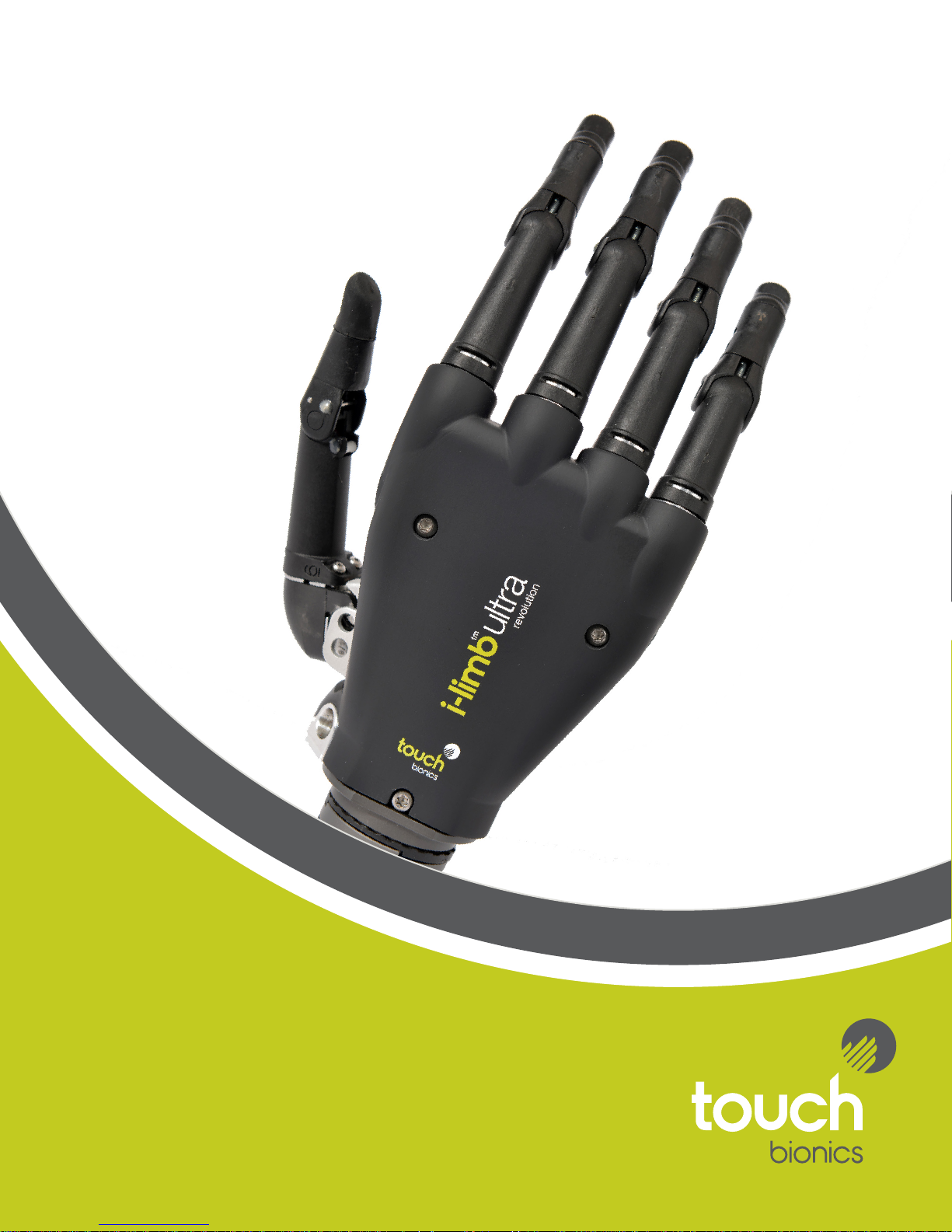
1.0 i-limb ultra revolution
1.1 Product Description
The i-limb ultra revolution is an externally powered, multiarticulating prosthetic hand which oers a range of features
beyond the functions of the traditional prosthetic hand.
Individually motorized digits and thumb, stall detection and the
unique biosim software used to control the i-limb ultra revolution
result in one of the most versatile prosthetic hands currently
available to the global market.
Users can choose from a wide selection of automated grips and
gestures to help complete daily tasks. Grips and gestures can
then be customized further for precise control.
The i-limb ultra revolution oers compliant grip through individually powered digits with stall out ability. A powered rotating
thumb in conjunction with a pulsing, enhanced grip (vari-grip),
an anti-drop safety feature (auto-grasp) and the wide range of
automated grip patterns lead to broad functionality.
1.2 Intended Use
The i-limb ultra revolution is intended to be used by patients with
upper limb loss or deciency
1.3 Prosthesis Overview
The hand serial number is positioned proximal to the base of the
thumb on the connection plate. The serial number should start
with a “R” and be followed by four numbers.
For users with exion wrist, hand serial number will be located at
the base of the thumb.
Part number: MA01140: Issue No. 4, December 2014
4 of 33
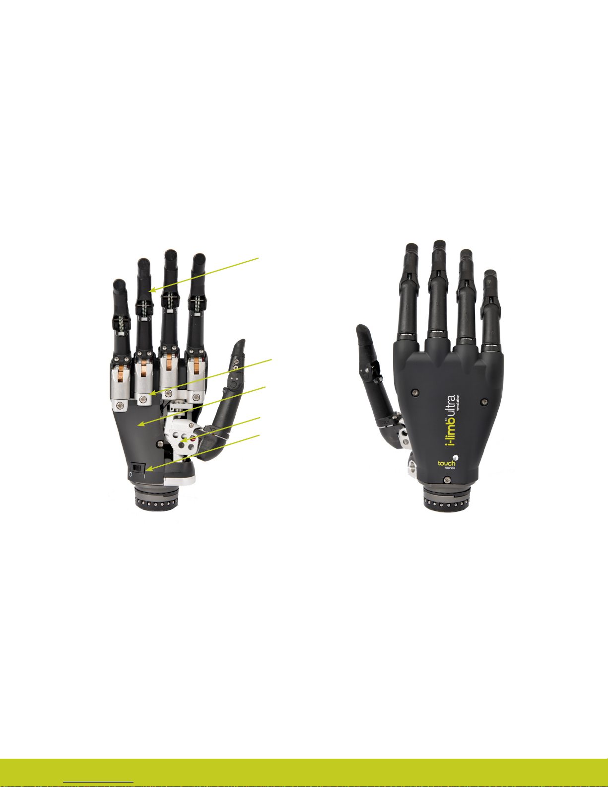
Motorized Digit
Knuckle
Palmar Fairing
Motorized Thumb
On / O Switch
Part number: MA01140: Issue No. 4, December 2014
2.0 Socket
2.1 Control Sites
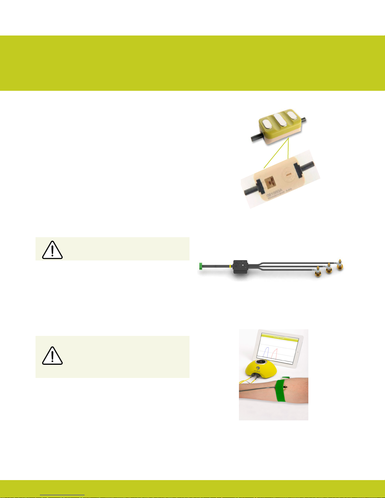
One option for control of the i-limb ultra revolution is electrodes.
There are two electrode options available for use with the i-limb
ultra revolution, compact electrodes (g. 1) or remote electrodes
(g. 2). For information regarding the tting of the Touch Bionics
Electrode, review the manual provided with the electrode.
Electrode Site Selection
The use of virtu-limb, the Touch Bionics’ myotesting system, is
recommended to determine the optimal placement of electrodes
(g. 3).
Figure 1. Electrode Options
Do not rely on previous myoelectrical testing.
Consult Touch Bionics training materials for information on
myotesting or download information on myotesting within the
software or mobile apps manuals at www.touchbionics.com/
downloads/document-library.
Use anatomical sites where the electrode will
maintain constant, even contact with the skin. Avoid
placing electrodes near socket interface trim lines,
bony areas, skin grafts or fatty tissue.
Figure 2. Remote Electrode
Figure 3. virtu-limb
Part number: MA01140: Issue No. 4, December 2014
6 of 33
2.2 Socket Fabrication
While fabricating the socket for the i-limb ultra revolution, special
considerations will need to be given to:
1. Battery placement, size and conguration
2. Electrode position or other control method
3. Charge port placement
4. Socket length and the overall length of the prosthesis in
comparison to the opposite side.
Clinicians should have prior experience with building externally
powered prosthetic sockets before tting the i-limb ultra
revolution.
Touch Bionics’ batteries, charger port and switch block components
should always be used with the i-limb ultra revolution.
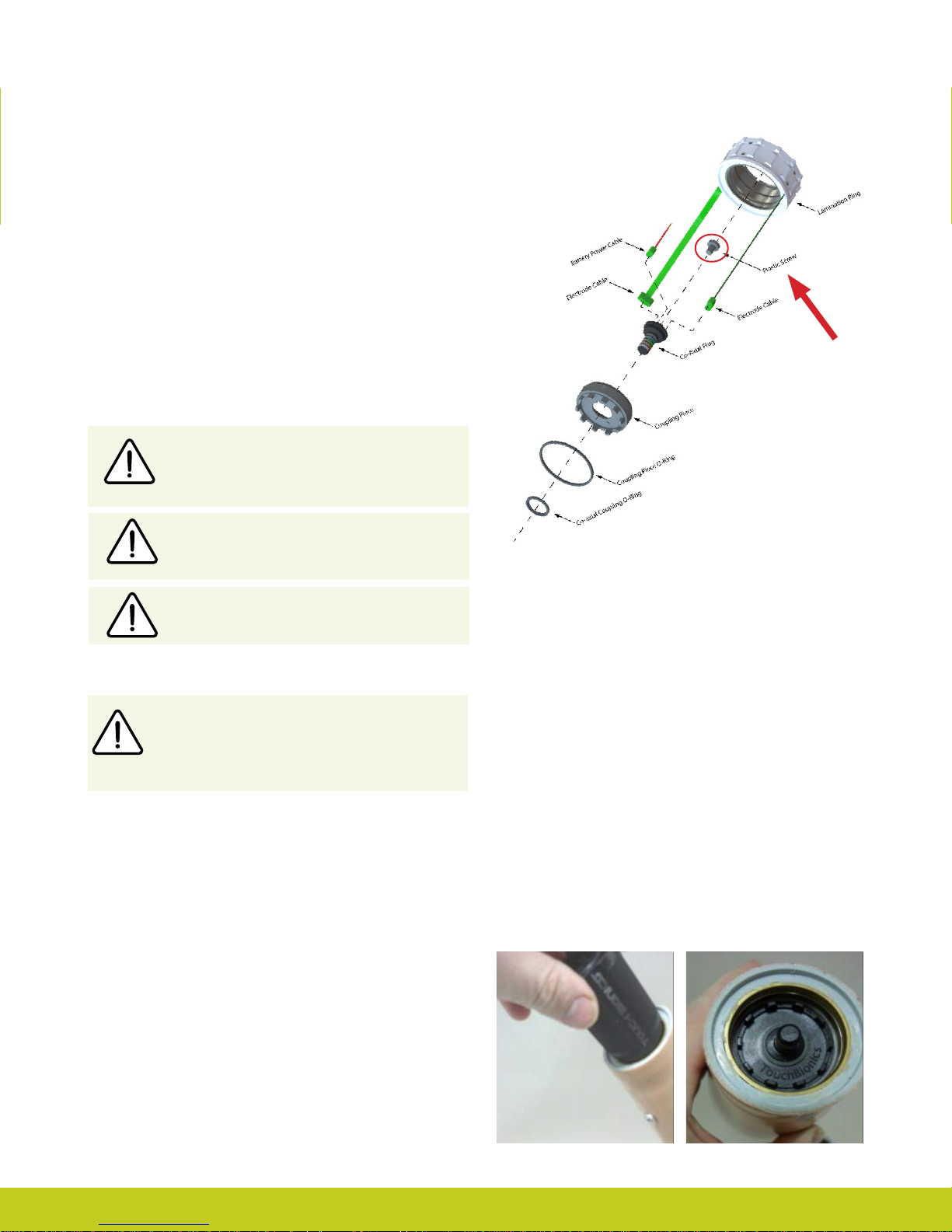
Prosthetist must ensure that the plastic screw provided
is utilized and properly tightened on the coaxial plug
(g.4) where the battery and electrodes connect, to
prevent loose connections .
We recommend that a rubber grommet or plastic cap
is placed over any socket holes to protect the integrity
of the electrode
Figure 4. Coaxial Plug
During socket maintenance, ensure a check of the
battery connector/co-axial plug interface is carried out
Socket Material
The use of Carbon ber is not recommended due to
electrical conductivity, if it is required to improve strength
then the carbon ber lamination must be grounded, if
used directly adjacent to electrodes (see Page 6). Please
contact Touch Bionics to order modied electrodes.
During socket fabrication, appropriate measures must be taken
to prevent sweat entering into the battery connector within
the lamination ring, which may result in a short circuit and
compromise use of the device. Conventional sweat prevention
methods include the use of drain holes and suction sealing
electrodes. Alternatively, silicone may be used to seal the interface
area between the battery connector and co-axial plug into the
prosthetic socket
Coupling Piece Assembly for QWD Wrist
Insert the castelation ring (coupling piece) into the lamination
ring and turn until seated. Insert retaining ring around the outside edge of the coupling piece and use QWD release tool to seat
the retaining ring. The QWD release tool is available to order
from Touch Bionics.
Part number: MA01140: Issue No. 4, December 2014
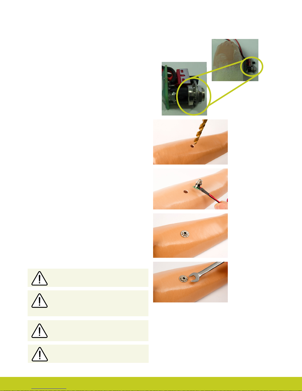
2.3 Charge Port Placement Assembly
It is important to provide sucient space for the charge port
between the inner and outer sockets. The charge port should be
positioned so that it is unaected by forces running through the
socket to prevent damage.
Create a drill hole of 8.0mm through the inner surface of the
prosthetic frame. Ensure a at surface has been created to
accommodate the charge port mounting frame (if installing a
switch block as an alternative to the charger port, create a drill
hole to cater for the panel mount).
Smooth the edges of the drill hole and insert the threaded
charge port. A minimum thread height of 3.2mm above the
socket surface is required for full engagement of washers and
locking nut.
Position the M8 Lock Washer and the M8 Flat Washer before
hand tightening the the locking nut.
Use a 3/8” wrench to tighten the locking nut. Do not overtighten.
Do not use pliers on the charge port.
Position the M8 Lock Washer and M8 Flat
Washer in place over the threaded shaft of the
charger port. Engage the M8 locking nut with
the threaded shaft and tighten rmly by hand.
The use of both the Lock Washer and Flat
Washer is vital to ensure the charge port is not
damaged by over tightening.
Do not overtighten!
Part number: MA01140: Issue No. 4, December 2014
8 of 33

2.4 Battery Options
Two battery options are available for the i-limb ultra revolution, both of which have been specically designed to meet the power
requirements of the hand. Battery selection should be based on available space within the socket fabrication, shape of the residual limb
and the expected level of use. The corresponding DC socket and switch block will also be required.
i-limb 1,300 mAh Battery i-limb 2,000 mAh Battery
Capacity 1,300 mAh 2,000 mAh
Length
Battery Dimensions
Dummy Battery
Dimensions
Application Moderate Use Heavy Use
Width 35mm (1.39”) 44mm (1.74”)
Height 6mm (0.24”) 7.5mm (0.30”)
Length 69mm (2.77”) 87mm (3.48”)
Width 35mm (1.39”) 45mm (1.80”)
Height
70mm (2.76”)
10mm (0.39”) Single cell
16mm (0.63”) Dual cell
80mm (3.17”)
11mm (0.44”) Single cell
19mm (0.76”) Dual cell
Part number: MA01140: Issue No. 4, December 2014
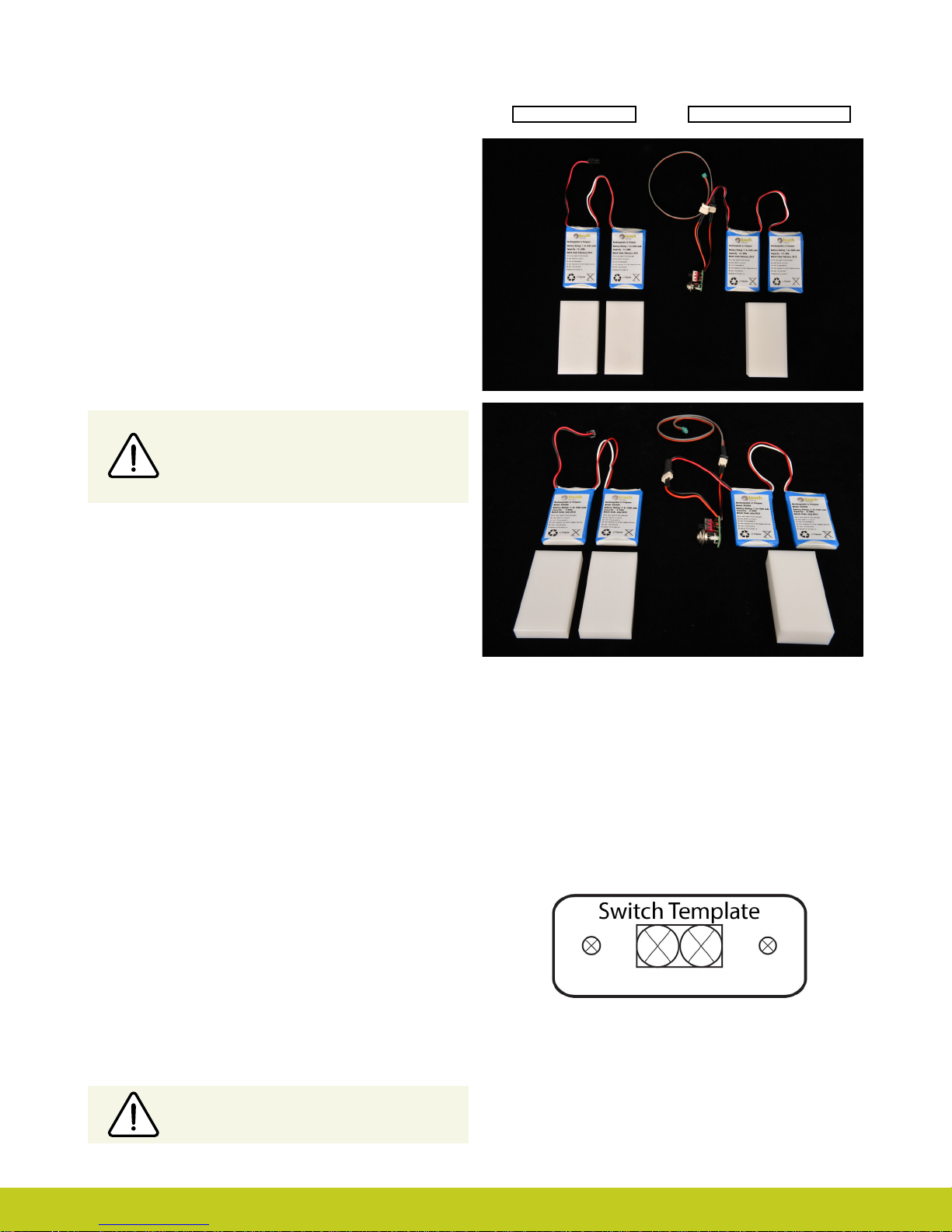
2.5 Battery Conguration
The images opposite show the 1,300 and 2,000mAh battery
options with battery dummy. The battery with DC connector and
battery with switch block connector are shown.
Only Touch Bionics batteries are approved
for use with the i-limb ultra revolution. Use of
alternative batteries will invalidate the warranty
and compromise general safety of the device.
DC Connector Switch Block Connector
2.6 Battery Installation
The battery is designed to be mounted inside the socket interface.
Ensure there is adequate space between the residual limb and the
wrist (or elbow) to accommodate the battery, charger port and
any other componentry. Use the battery dummy to fabricate a
relief for the battery in the socket interface.
When planning battery location and dummy placement for
fabrication, keep in mind a maximum distance of 135mm is
possible between cells due to wire length.
Easier access to the on/o switch may be possible by installing a
switch block; this allows the on/o switch to be positioned in a
more proximal position on the forearm. The use of a switch block
also provides an additional accessory switch for temporarily
disabling an electric wrist rotator or other electrical device, when
needed.
Installing i-limb Power Pack
Utilize battery dummies on top and bottom of socket to create
necessary space to accommodate battery housing.
Use standard fabrication processes and technique to create an
opening in the socket to accommodate battery housing.
When using a switch block, it is recommended that you use the
provided Switch Template to guide drill holes.
Ensure there is no contact between the battery
housing and inner socket
Part number: MA01140: Issue No. 4, December 2014
10 of 33
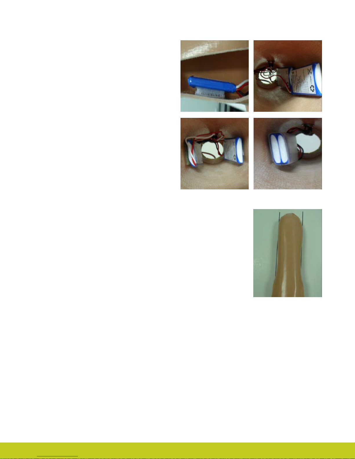
Battery Placement
Use Velcro™ to position the batteries on the pre-prepared
at surfaces to prevent distortion.
Battery Placement for a Long Residual Limb
Consideration of battery placement is particularly important
in longer sockets. The shape of the inner socket must also be
considered.
If the residual limb is long, wrist disarticulation or bulbous, the
position of the battery dummies and charge port are best placed
midway up the arm along the inner socket ensuring they will not
impact the ability to don/do the prosthesis and that the position will not result in pressure from the residual limb that could
distort the battery.
Placement of batteries should allow for removal of the inner
socket.
If the socket has a bulbous distal end, do not position batteries or
charger port around the narrow region of the prosthesis.
Part number: MA01140: Issue No. 4, December 2014
 Loading...