

Page 1
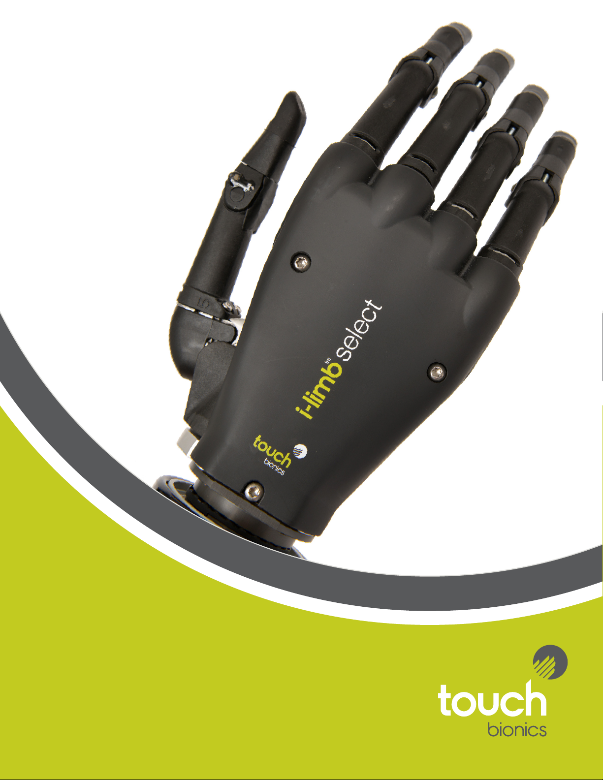
i-limbTM select
Manual
Part number: MA 01155: Issue No. 4, January 2015
Page 2

This is an i-limb ultra that has been refurbished. This document provides instruction for prosthetists in the
tting and servicing of the i-limb select and should be read in full prior to tting. It is highly recommended
that the use of this manual is made in conjunction with instruction from a clinician experienced in upper limb
and myo-electric prostheses.
This symbol signies important information and is used throughout the manual.
2
Page 3

Table of Contents
1. i-limb select 1.1 Product Description
1.2 Intended Use
1.3 Prosthesis Overview
1.4 Features catalogue
2. Socket 2.1 Control Sites
2.2 Socket Fabrication
2.3 Charge Port Placement Assembly
2.4 Battery Options
2.5 Battery Conguration
2.6 Battery Installation
2.7 i-limb Power Pack
2.8 Battery Charging
3. Wrist 3.1 Wrist Connection Options
3.2 Quick Wrist Disconnect (QWD)
3.3 Wrist Disarticulation
4. Adjustments 4.1 Digit Conguration
4.2 Digit Installation
4.3 Thumb Installation
5. Covers 5.1 Cover Options
6. biosim app clinician version 6.1 biosim app Overview
6.2 Getting Started
7. my i-limb patient version 7.1 my i-limb Overview
7.2 Getting Started
8. Support Information 8.1 General Safety, Warnings and Precautions
8.2 Troubleshooting
9. Appendix 9.1 Technical Information
9.2 i-limb select Information
9.3 Component Compatibility
9.3.1 EMC and Electrical Information
9.4 Warranty
Part number: MA 01155 Issue No. 4, January 2015
3 of 50
Page 4

1.0 i-limb select
1.1 Product Description
The i-limb select is an externally powered, multi-articulating
prosthetic hand which oers a range of features beyond the
functions of the traditional prosthetic hand.
Individually motorized digits and the unique biosim and my i-limb
app used to control the i-limb select result in one of the most
versatile prosthetic hand currently available to the global market.
Users can choose from a wide selection of automated grips and
gestures to help complete daily tasks. Grips and gestures can
then be customized further for precise control.
The i-limb select oers compliant grip through individually
powered digits with stall out ability. A manually rotating thumb
in conjunction with a pulsing, enhanced grip (vari-grip), and the
wide range of automated grip patterns lead to broad functionality.
1.2 Intended Use
The i-limb select is intended to be used by patients with upper
limb loss or deciency
1.3 Prosthesis Overview
The i-limb select is available in small or medium sizes. The hand
serial number is positioned proximal to the base of the thumb on
the connection plate. The serial number will start with a “Q” and
be followed by four numbers.
Part number: MA 01155 Issue No. 4, January 2015
4 of 50
Page 5
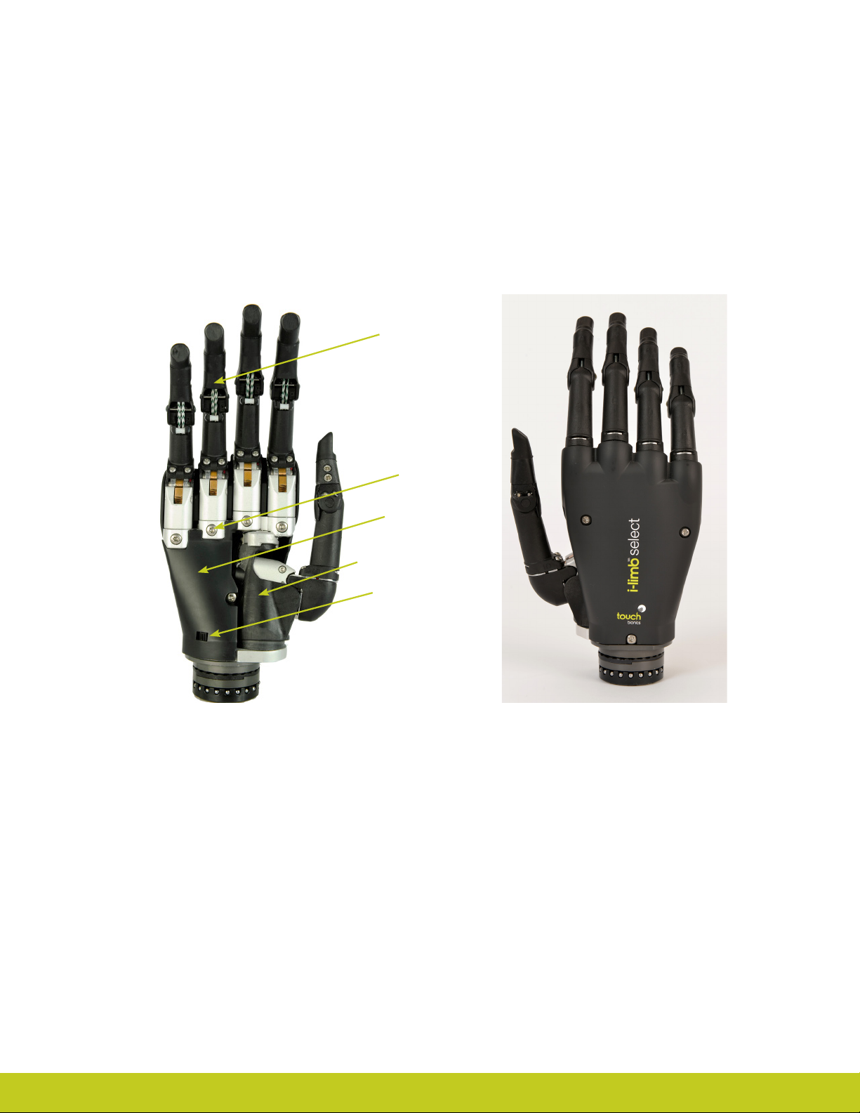
Motorized Digit
Knuckle
Palmar Fairing
Manual Thumb Rotator
On / O Switch
Part number: MA 01155 Issue No. 4, January 2015
Page 6

1.4 Features Catalogue
The i-limb select has 12 dierent grip options available. These grips can be accessed through biosim and the my i-limb app. This
following Features Catalogue will review the various available grips and provide a functional description of each.
Precision Pinch Grip Options
Precision pinch grip options are best for picking up small items between and the thumb and index nger. There are 4 options
available depending on how you want the other digits to perform while doing the pinch. The most popular is Thumb Precision Pinch
Closed.
Standard Precision Pinch Opened
middle, ring and little nger remain fully
opened and switch o. Index nger and
thumb provide grip.
Thumb Precision Pinch Opened
middle, ring and little nger remain
fully opened and switch o. Thumb
automatically moves to a partially closed
position. Index nger will move to provide
grip against a xed thumb.
Standard Precision Pinch Closed
middle, ring and little nger automatically
close and switch o. Index nger and
thumb provide grip.
Thumb Precision Pinch Closed
middle, ring and little nger automatically
close and switch o. Thumb automatically
moves to a partially closed position. Index
nger will move to provide grip against a
xed thumb.
Tripod Grip Options
Tripod Grip Options provide a grip where the thumb is meeting up with the index and middle digits. Typically the thumb is rotated
between the index and middle to provide more stability when gripping slightly larger objects than those with the precision pinch
grips. As a result of having a motor in each digit and the hand conforming to the shape of the object being held, the hand will
automatically form a tripod grip when the object is small enough to only be gripped between the thumb, index, and middle digits.
The advantage of using the tripod grip options is if you want the ring and small digits to stay either fully open or fully closed when
gripping.
Standard 3 Jaw Chuck (Tripod) Opened
ring and little nger remain fully opened and
switch o. Thumb, index and middle ngers
move to provide grip.
Standard 3 Jaw Chuck (Tripod) Closed
ring and little nger move to terminal
close. Thumb, index and middle ngers
move to provide grip.
Thumb 3 Jaw Chuck (Tripod) Opened
ring and little nger remain fully opened and
switch o. Thumb automatically moves to a
partially closed position. Index and middle
ngers move to provide grip against a xed
thumb.
Part number: MA 01155 Issue No. 4, January 2015
Thumb 3 Jaw Chuck (Tripod) Closed
ring and little nger move to terminal
close. Thumb automatically moves to a
partially closed position. Index and middle
ngers move to provide grip against a
xed thumb.
6 of 50
Page 7
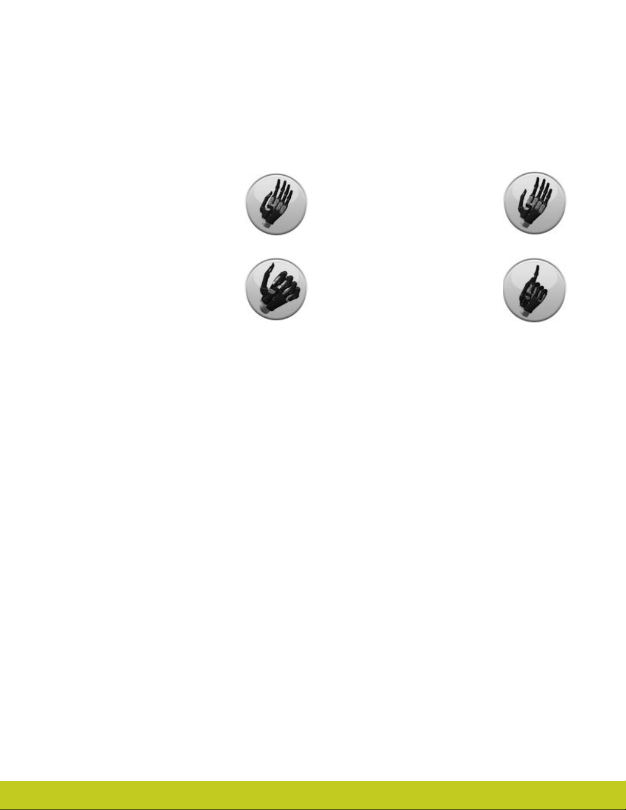
Additional Grip and Gesture Options
With these additional grip patterns and gestures, consider how often you perform dierent tasks and if having a program for that
activity would make it easier/faster for you to perform. Since each digit has its own motor, you can put pressure against any digit to
stop it from moving (called stalling the digit). Many of these additional grips can be performed by stalling one or more digits. If it is a
task that is not performed often (maybe using index point to press the “Shift” key on a keyboard) then you may prefer to just stall the
digit. However, if you frequently perform the task or want to go into the position without needing to put the hand against the table
or your other hand, then programming the grip may be the better option.
Thumb Park Continuous
all four ngers remain open and switch o,
only the thumb will move.
Lateral Grip
all four ngers fully close and switch o.
Only thumb will move.
Thumb Park Quick
all four ngers remain open and switch
o, for 1.5 seconds the thumb will close
and then automatically return to an open
position.
Index Point
thumb, little, ring and middle ngers close
and switch o. Only the index nger will
move.
Part number: MA 01155 Issue No. 4, January 2015
Page 8
2.0 Socket
2.1 Control Sites
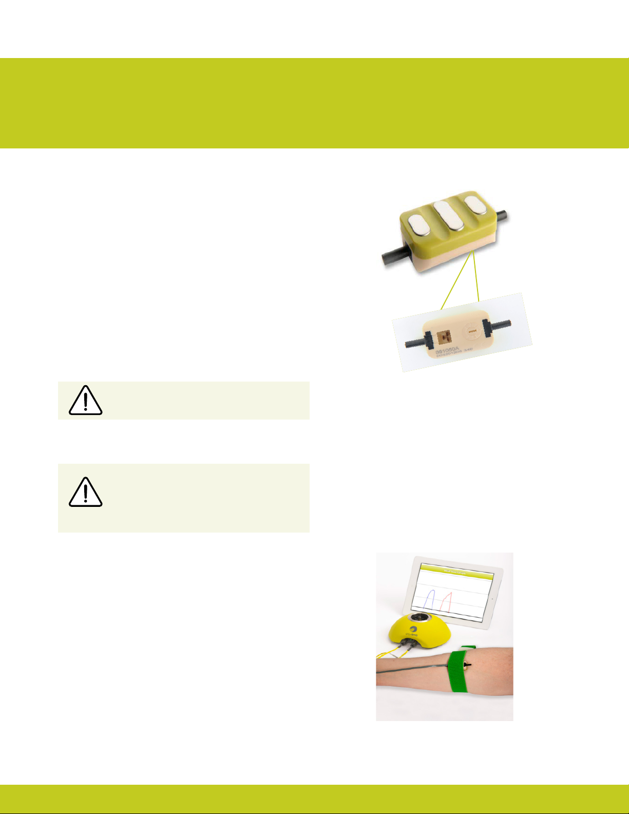
The i-limb select is controlled by compact electrodes
(g. 1).
For information regarding the tting of the Touch Bionics
electrode, review the manual provided with the electrode.
Electrode Site Selection
The use of virtu-limb, the Touch Bionics’ myo-testing system,
is recommended to determine the optimal placement of
electrodes (g. 2). virtu-limb is not included with the i-limb
select. Contact Touch Bionics for information about ordering
virtu-limb.
Do not rely on previous myo-electrical
testing.
Consult Touch Bionics training materials for information on myotesting.
Figure 1. Compact Electrode
Use anatomical sites where the electrode will
maintain constant, even contact with the skin.
Avoid placing electrodes near socket interface
trim lines, bony areas, skin grafts or fatty tissue.
Figure 2. virtu-limb
Part number: MA 01155 Issue No. 4, January 2015
8 of 50
Page 9
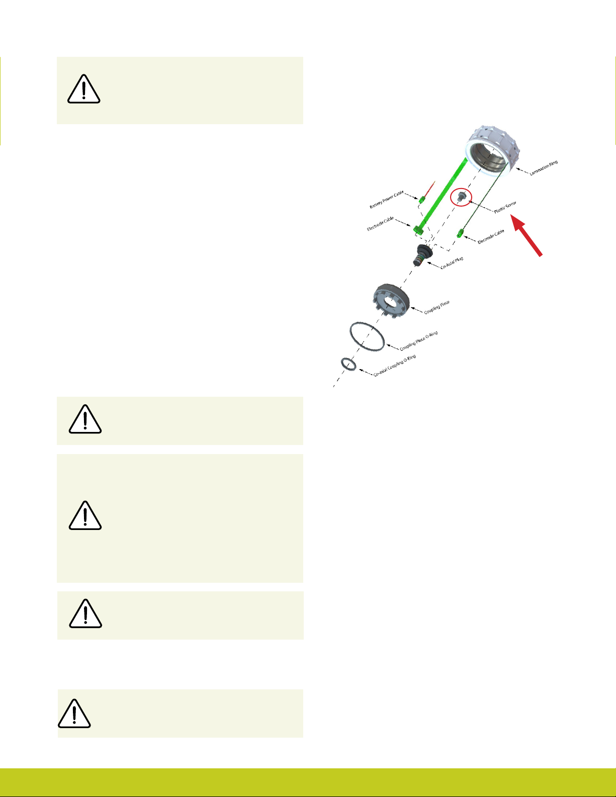
Prosthetist must ensure that the plastic screw provided
is utilized and properly tightened on the coaxial plug
(g.3) where the battery and electrodes connect, to
prevent loose connections .
2.2 Socket Fabrication
While fabricating the socket for the i-limb select, special
considerations will need to be given to:
1. Battery placement, size and conguration
2. Electrode position
3. Charge port placement
4. Socket length and the overall length of the prosthesis in
comparison to the opposite side.
Clinicians should have prior experience with building externally
powered prosthetic sockets before tting the i-limb select.
Touch Bionics’ batteries, charger port and switch block
components should always be used with the i-limb select.
Figure 3. Coaxial Plug
We recommend that a rubber grommet or plastic cap
is placed over any socket holes to protect the integrity
of the electrode.
During socket fabrication, appropriate measures must
be taken to prevent sweat entering into the battery
connector within the lamination ring, which may result
in a short circuit and compromise use of the device.
Conventional sweat prevention methods include the
use of drain holes and suction sealing electrodes.
Alternatively, silicone may be used to seal the interface
area between the battery connector and co-axial plug
into the prosthetic socket.
During socket maintenance, ensure a check of the
battery connector/co-axial plug interface is carried out.
Socket Material
The use of Carbon ber is not recommended due to
electrical conductivity.
Part number: MA 01155 Issue No. 4, January 2015
Page 10

Coupling Piece Assembly for QWD Wrist
Insert the castelation ring (coupling piece) into lamination ring
and turn until seated. Insert retaining ring around outside edge
of coupling piece and use QWD release tool to seat the retaining ring. The QWD release tool is available to order from Touch
Bionics.
Battery Placement
Use Velcro® to position the batteries on the pre-prepared
at surfaces to prevent distortion.
Battery Placement for a Long Residual
Limb
Consideration of battery placement is particularly important
in longer sockets. The shape of the inner socket must also be
considered.
If the residual limb is long or bulbous, the position of the battery
dummies and charge port are best placed midway up the arm
along the inner socket ensuring they will not impact the ability
to don/do the prosthesis and that the postion will not result in
pressure from the residual limb that could distort the battery.
Placement of batteries should allow for removal of the inner
socket.
If the socket has a bulbous distal end, do not position batteries
or charger port around the narrow region of the prosthesis.
Part number: MA 01155 Issue No. 4, January 2015
10 of 50
Page 11

2.3 Charge Port Placement Assembly
It is important to provide sucient space for the charge port
between the inner and outer sockets. The charge port should be
positioned so that it is unaected by forces running through the
socket to prevent damage.
Create a drill hole of 8mm through the inner surface of the
prosthetic frame. Ensure a at surface has been created to
accommodate the charge port mounting frame (if installing a
switch block as an alternative to the charger port, create a drill
hole to cater for the panel mount).
Smooth the edges of the drill hole and insert the threaded
charge port. A minimum thread height of 3.2mm above the
socket surface is required for full engagement of washers and
locking nut.
Position the M8 Lock Washer and the M8 Flat Washer before
hand tightening the the locking nut.
Use a 3/8” wrench to tighten the locking nut.
Do not overtighten.
Do not use pliers on the charge port.
Position the M8 Lock Washer and M8 Flat
Washer in place over the threaded shaft of the
charger port. Engage the M8 locking nut with
the threaded shaft and tighten rmly by hand.
The use of both the Lock Washer and Flat
Washer is vital to ensure the charge port is not
damaged by over tightening.
Do not overtighten!
Part number: MA 01155 Issue No. 4, January 2015
Page 12
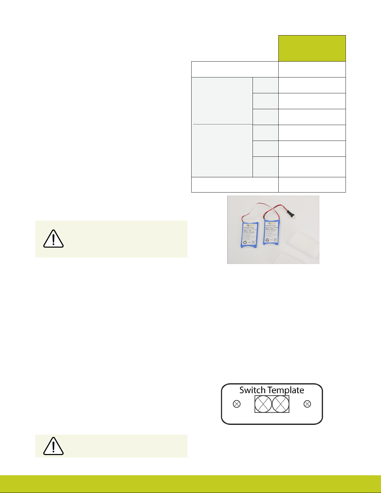
2.4 Battery Options
The i-limb select comes with a 1,300mAh battery. This
battery has been specically designed to meet the power
requirements of the hand.
i-limb 1,300 mAh
Battery
Capacity 1,300 mAh
Length 70mm (2.76”)
2.5 Battery Conguration
The image opposite shows the 1,300mAh battery option .
Only Touch Bionics batteries are approved
for use with the i-limb select. Use of
alternative batteries will invalidate the
warranty.
2.6 Battery Installation
The battery is designed to be mounted inside the socket
interface. Ensure there is adequate space between the residual
limb and the wrist (or elbow) to accommodate the battery, charger port and any other componentry. Use the battery dummy to
fabricate a relief for the battery in the socket interface.
Battery Dimensions
Dummy Battery
Dimensions
Application Moderate Use
Width 35mm (1.39”)
Height 6mm (0.24”)
Length 69mm (2.77”)
Width 35mm (1.39”)
Height
10mm (0.39”) Single cell
16mm (0.63”) Dual cell
When planning battery location and dummy placement for
fabrication, keep in mind a maximum distance of 135mm is
possible between cells due to wire length.
Installing i-limb Power Pack
Utilize battery dummies on top and bottom of socket to create
necessary space to accommodate battery housing.
Use standard fabrication processes and technique to create an
opening in the socket to accommodate battery housing.
When using a switch block, it is recommended that you use the
provided Switch Template (g. 4) to guide drill holes.
Ensure there is no contact between the battery
housing and inner socket
Part number: MA 01155 Issue No. 4, January 2015
Figure 4
12 of 50
Page 13
Do not apply excessive force to the charger
socket interface during assembly.
A minimum of 2mm of free space surrounding the charger port
should be provided.
A at surface is needed to secure the charger port to the socket
interface frame. This may require additional shaping of the frame
section above the dummy battery. Use the Velcro
®
strip supplied to
attach the battery to the inside of the socket interface.
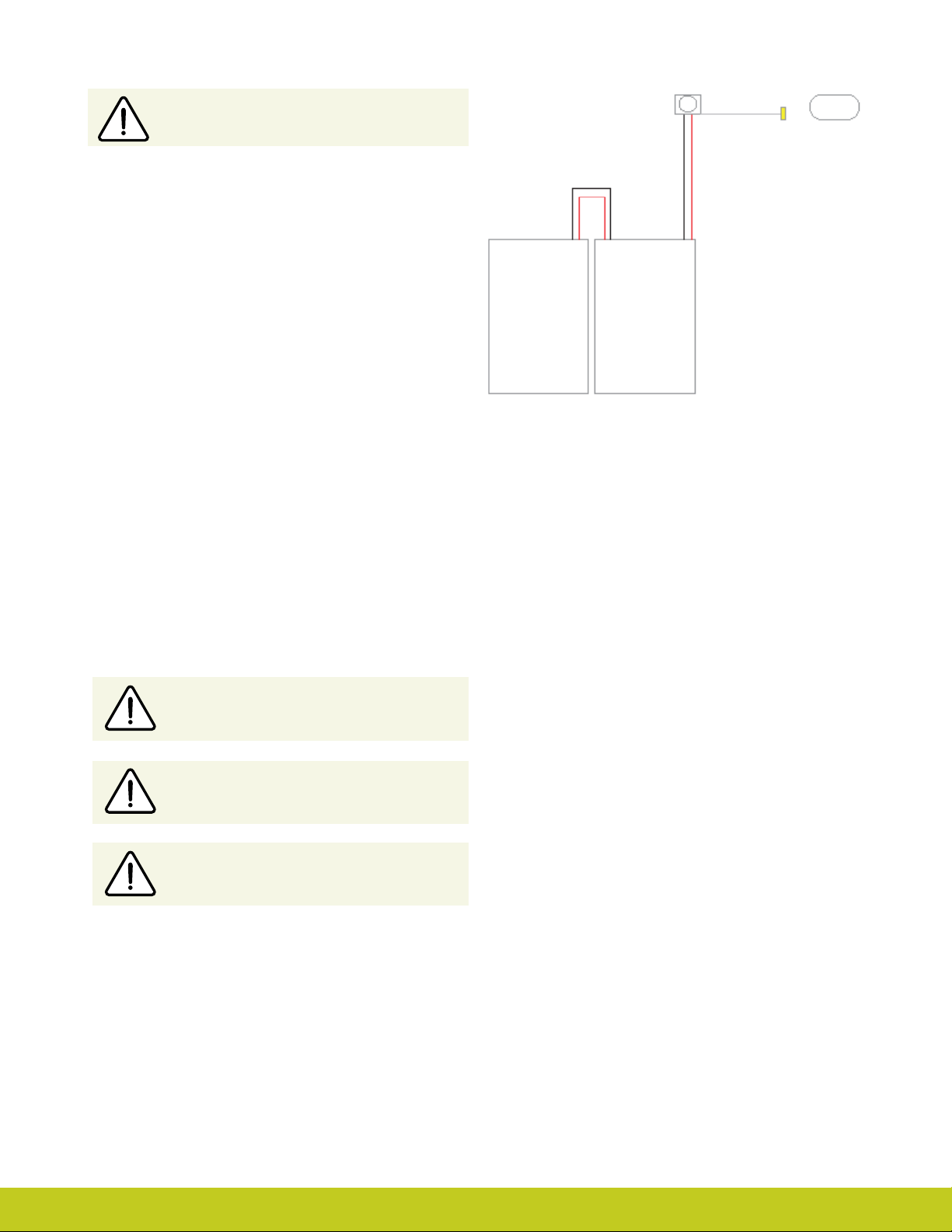
Wiring Schematic for 1300mAh Low Prole
Battery with D.C. Socket
2.5mm D.C. Socket
Co-axial Bush/Rotator
If the area between the residual limb and the lamination ring is
insucient to house the battery, you will need to position the
battery between the socket interface and the frame. This will be
necessary when:
• the residual limb is longer than 60% of the humeral or forearm
section of the prosthesis
• the battery is too large for the space available in the socket
interface frame
Cutting or modifying the battery wires in any
way will invalidate the warranty.
Low Prole Battery Cells Placed Side by Side
Do not bend or shape the battery in any way.
Ensure the battery is not subject to continued
pressure once tted.
Part number: MA 01155 Issue No. 4, January 2015
Page 14
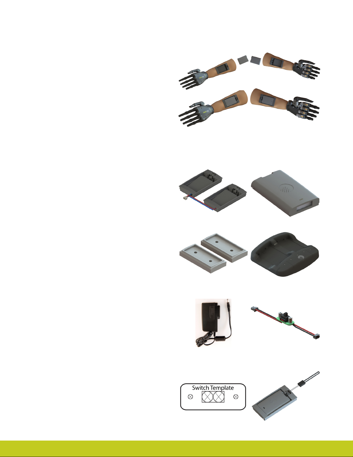
2.7 i-limb Power Pack
i-limb Power Pack (ordered separately) are for users who want the
ability to easily replace batteries.
Battery housing is fabricated on top and bottom of socket,
allowing for easy access.
Top of socket
Bottom of socket
i-limb Power Pack kit
i-limb Power Pack includes the following items:
• 1 dual battery housing unit (g. 5).
• 4 Removable 800 mAh batteries (g. 6) with low battery LED indicator.
Battery LED will glow RED when batteries are below 10% charge.
• 2 Battery housing dummies (g. 7).
• Dual battery charger base unit (g. 8).
• Wall charging unit (g. 9).
• Switch Assembly. Switch Block is typically used in conjunction with
a wrist rotator or for patients who would like a power o control on
the socket) (g. 10).
• Switch template Switch Assembly (if Switch Assembly is ordered)
(g. 11). This template is to be applied to the desired position on the
socket to help guide drill holes.
• 2 Battery Pull cords (g. 12). Benecial for bi-lateral patients, the
battery pull cord provides a simple solution for removing the battery
in your socket.
Figure. 5 Figure. 6
Figure. 7
Figure. 9 Figure. 10
Figure. 8
• Country specic charger plugs.
• Car charger.
Part number: MA 01155 Issue No. 4, January 2015
14 of 50
Figure. 11
Figure. 12
Page 15

2.8 Battery Charging
Please review the below Instructions for proper internal battery
charging.
Only use supplied Touch Bionics charger to charge
battery. Depending on your location, you will
receive one of the below chargers (g. 14, or g. 15)
The patient will need to remove the socket from their arm and
turn the i-limb device o. The on/o switch is pictured in g 13.
i-limb device is o when switch is in left position.
Insert the charger (g. 14 or g. 15) into the power outlet. The
charger will need to be inserted into the power outlet prior to
connecting to the charge port. To charge, insert the charger
lead connector into the charge port. A “click” should be heard
on connection. If the green light is on when you rst plug in the
device, ensure the switch block is o.
Charging time is approximately:
1,300 mAh battery- 90 minutes
2,000 mAh battery- 180 minutes
The light display for g. 14 is:
• Solid Red – charging
• Solid Green – fully charged or idle
• Continuous ashing red – fault condition
• Rapid ashing amber – Threshold state between charging
and fully charged ( should only last for 1-2 seconds)
• Continuous ashing red or green – Connection Error.
Remove charger lead connector from the charge port.
Ensure charger is plugged in and switched on at the mains.
Re-insert the charger lead connector into the charge port.
The light display for g. 15 is:
• Solid Amber – on standby
• Slow ashing amber – pre-charge mode
• Rapid ashing amber – Error
• Slow ashing green – maintenance charge
• Rapid ashing green – rapid charge
• Solid green – fully charged
To remove the charger lead connector from the i-limb select,
grip the connector and pull directly away from the port. Consult
Warnings and Precautions for additional information.
Figure. 13
On/O Switch
Figure 14
Figure 15
If the patient intends to travel outside of their home country,
they will need to ensure they have a Touch Bionics charger that
will work in the country to which they are traveling. Additional
chargers are available from Touch Bionics.
To ensure the i-limb select is continually
functional, charge at the end of each day.
Replace the battery annually for optimal
performance.
Part number: MA 01155 Issue No. 4, January 2015
Do not pull cable to remove the lead.
Switch the hand OFF to preserve battery power
when not in use.
Page 16

i-limb Power Pack Charger
i-limb Power Pack batteries for i-limb select should only be
charged using the Touch Bionics battery charger (g. 16)
supplied. Place the batteries in the charger as illustrated. Insert
the charger lead from the battery powerpack into the charge
port. Insert the charger into the power outlet.
Charging time from full discharge is approximately 2 hours.
Figure. 16
On the base plate of the charger (g. 17) you will see the various
light sequences:
• Middle light on: Charger is plugged in
• 2nd and 5th lights blinking Green: Batteries are charging
• 2nd and 5th lights solid Green: Batteries are charged
• 1st and 4th Red lights on: Battery fault, unplug and try
again. If lights continue to illuminate, contact Touch Bionics
Customer Support.
Only use the plug to disconnect the charger, never
pull the cable to remove the lead.
Figure. 17
Part number: MA 01155 Issue No. 4, January 2015
16 of 50
Page 17
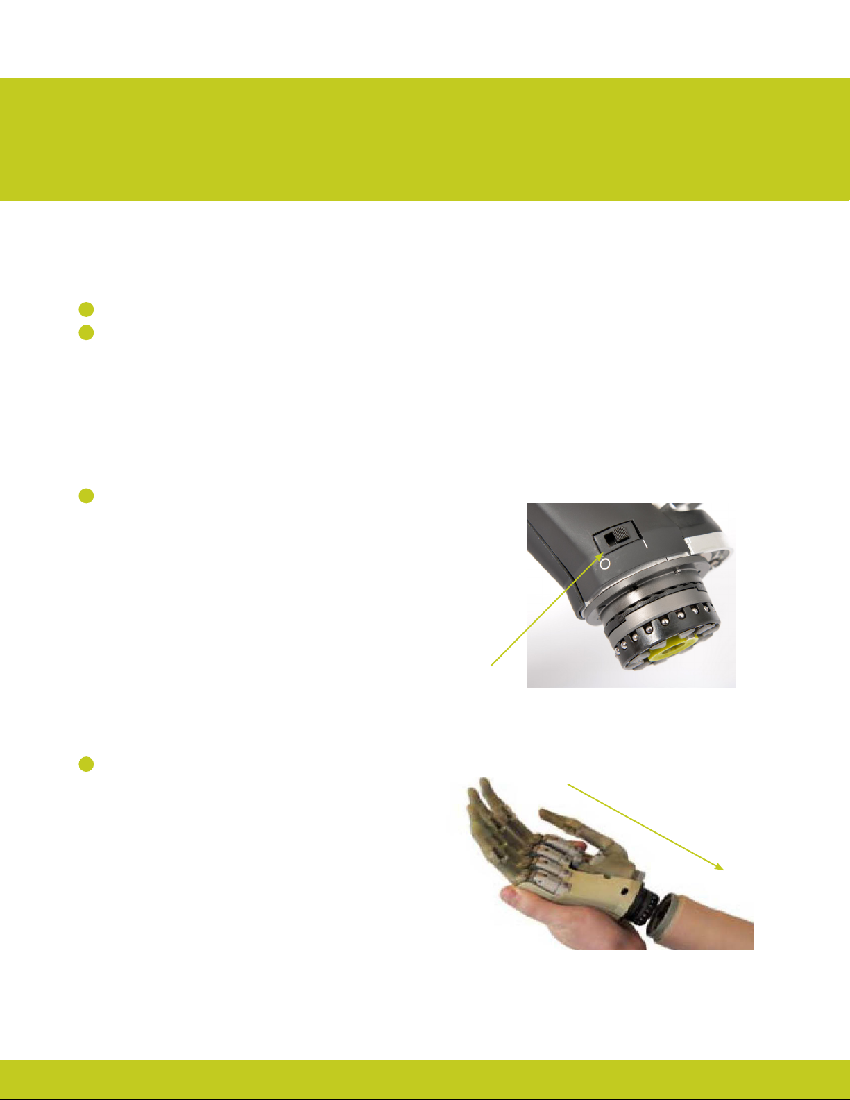
3.0 Wrist
3.1 Wrist Connection Options
The following wrist connection options are available for the i-limb
select:
1
Quick Wrist Disconnect (QWD)
2
Wrist Disarticulation
3.2 Quick Wrist Disconnect (QWD)
The QWD is supplied by Touch Bionics.
Connecting the i-limb select using the QWD
1
Ensure the i-limb select is switched o.
2
Align the QWD connection of the i-limb select with the
connection in the forarm socket.
On/O Switch
Part number: MA 01155 Issue No. 4, January 2015
Page 18
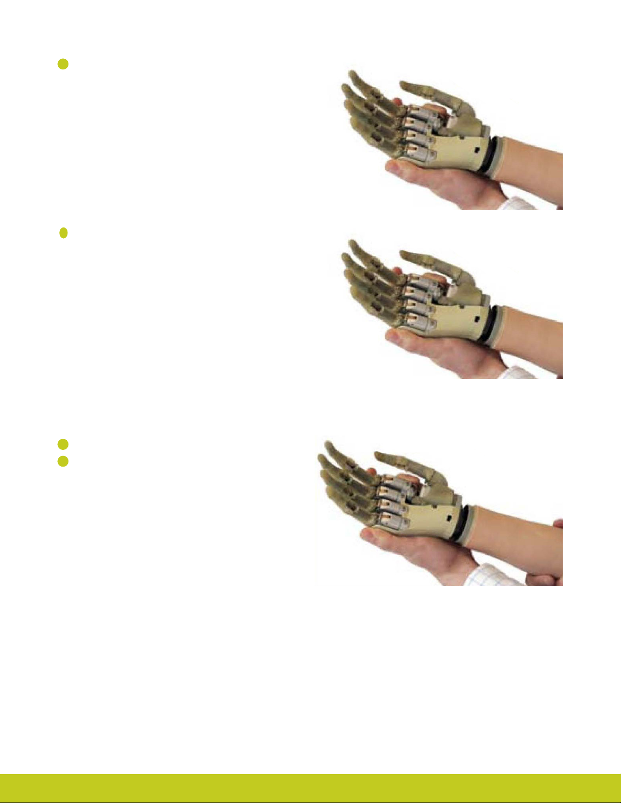
3
Engage the coupling.
Test the connection is fully engaged with a slight rotation.
4
Disconnecting the i-limb select using the
QWD
1
Ensure the i-limb select is switched o.
2
Support the i-limb select in the palm of the hand.
Part number: MA 01155 Issue No. 4, January 2015
18 of 50
Page 19
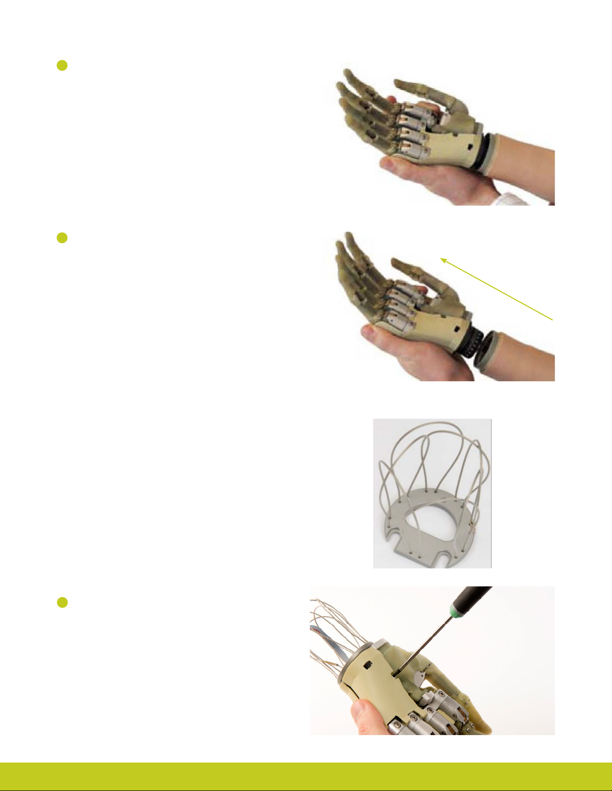
2
Rotate the i-limb select through 360° in either direction until
3
a click is heard
3
4
The i-limb select will now disengage from the socket.
Support the hand and withdraw away from the socket
3.3 Wrist Disarticulation
The wrist disarticulation is fabricated directly into the socket frame
and then attached to the i-limb select by the following steps:
1
Disconnect the Palm Fairing from the i-limb select chassis
by unscrewing the screw in the palmar surface using a T10
Screwdriver (available for order).
Part number: MA 01155 Issue No. 4, January 2015
Page 20
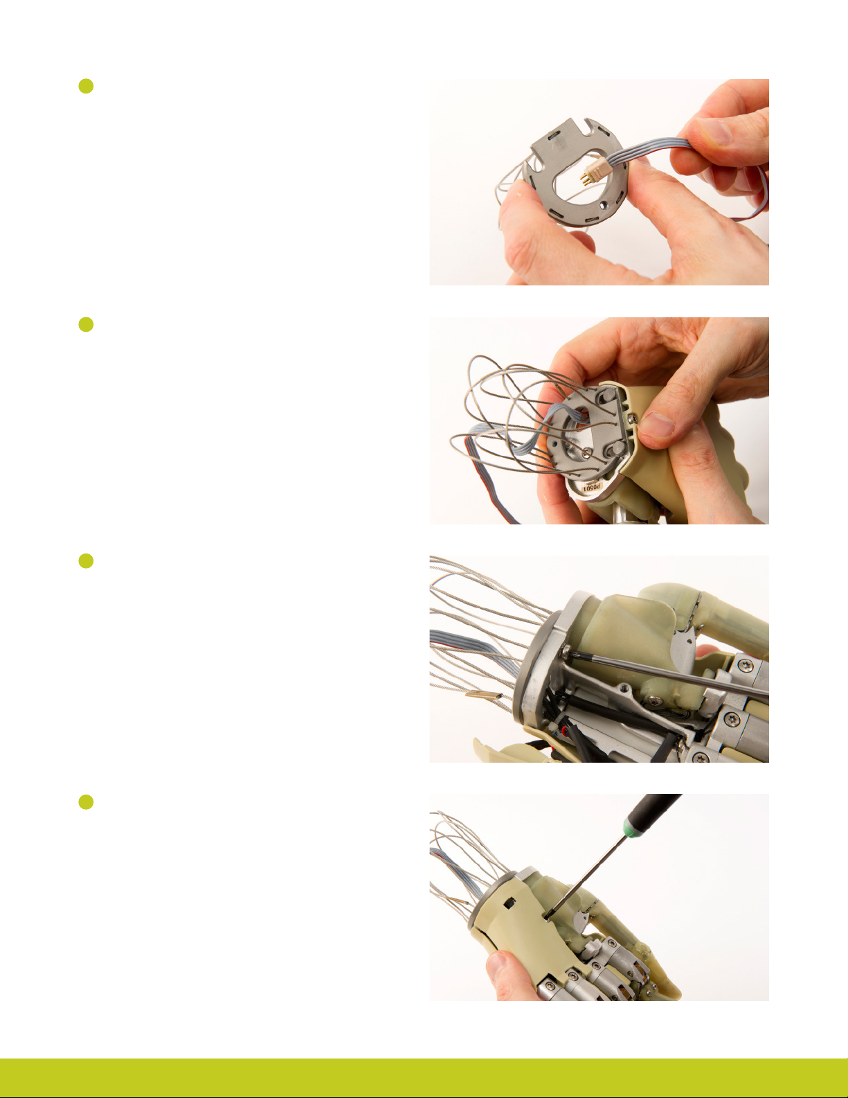
2
Remove the Wrist Disarticulation and feed the power cable
through.
3
Align the slots and slide the Wrist Disarticulation plate onto
the WD Lamination Plate at base of the i-limb select ensuring
it is rmly engaged.
4
Secure the Wrist Disarticulation plate to the WD Lamination
Plate using a T10 screw and a T10 Screwdriver.
5
Replace the Palm Fairing onto the chassis by hand tightening
the screw in the palmar surface using a T10 Screwdriver.
Ensure that the Palm Fairing does not pinch the wiring.
Part number: MA 01155 Issue No. 4, January 2015
20 of 50
Page 21

6
Fabrication of the Wrist Disarticulation into the socket
must allow for disengagement of the hand from the Wrist
Disarticulation plate. Otherwise complete fabrication of the
Wrist Disarticulation into the socket in the usual manner.
To disconnect the Wrist Disarticulation from the i-limb select
complete the above steps in reverse:
1
Disconnect the Palm Fairing from the Chassis. Be careful to
not damage wiring when removing the Palm Fairing.
2
Loosen the WD Lamination Plate Screw from the Wrist
Disarticulation plate.
3
Slide the Wrist Disarticulation o the base of the i-limb select.
4
Separate the i-limb select from the Wrist Disarticulation,
drawing the Basket cable through the Wrist Disarticulation.
Part number: MA 01155 Issue No. 4, January 2015
Page 22
4.0 Adjustments
4.1 Digit Conguration
Individual digits for the i-limb select are manufactured as sizes
2, 3, 5 and 6. Sizes 2 and 3 contain a small motor, while sizes 5
and 6 contain a a larger motor. The standard digit conguration
of the small and medium sized i-limb select is outlined in the
table.
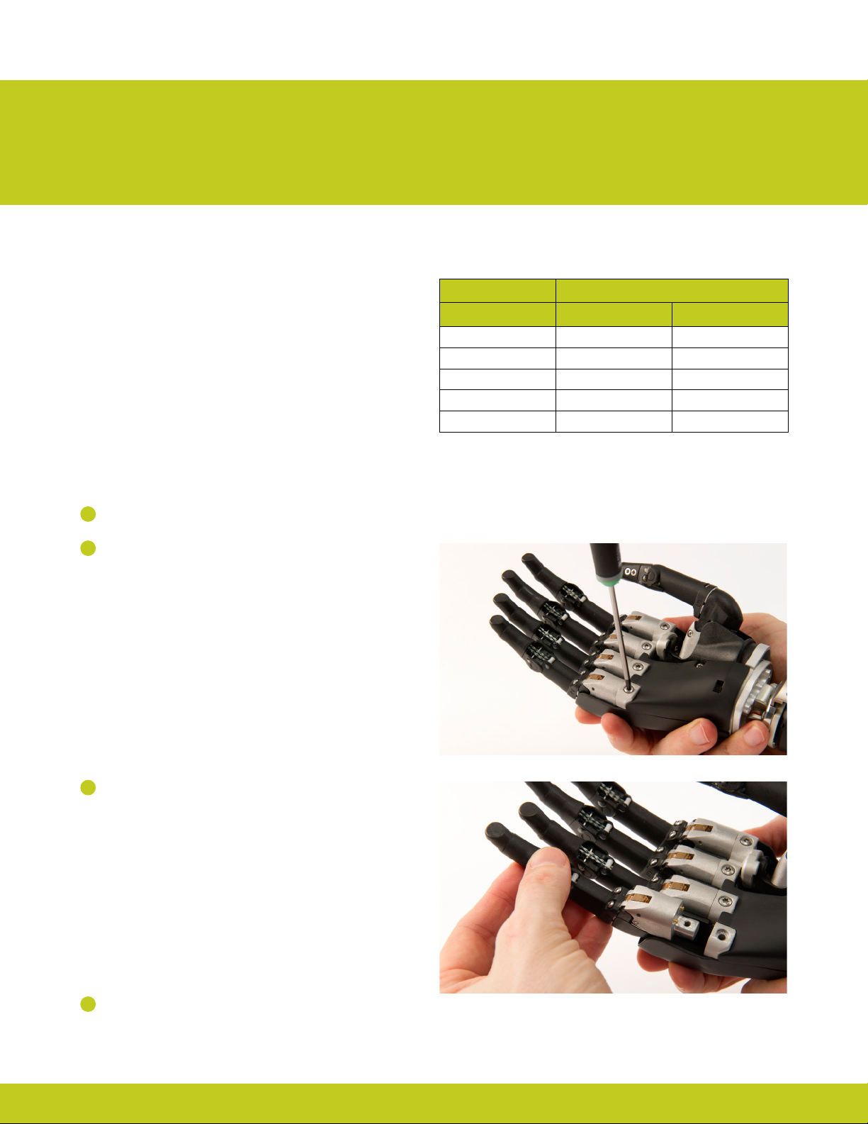
4.2 Digit Installation
The i-limb select is only compatible with Touch Bionics i-limb
select digits. To install a digit, ensure that the correct digit size is
selected. Remove the digit by the following steps:
1
Ensure the i-limb select is switched o.
2
1
Support the i-limb select in the palm of the hand with the
digits in the fully open position. Insert the T10 Screwdriver
in the screw of the Knuckle block (supplied see 4.3).
i-limb select size
Digit Small Medium
Thumb 5 6
Index 5 6
Middle 5 6
Ring 3 5
Little 2 2
3
Loosen the Knuckle block screw while supporting the digit,
remove the digit.
1
4
Select the appropriate sized replacement digit and follow
the steps in reverse order to replace.
Part number: MA 01155 Issue No. 4, January 2015
22 of 50
Page 23
It is recommended that you discard the used screws as the antivibration pad on the screw shaft will be deformed during use.
Digit screws should be replaced using the new screws provided.
Do not over tighten screws.
If there is resistance while tightening the screw
check for cross threading by removing and reinserting the screw.
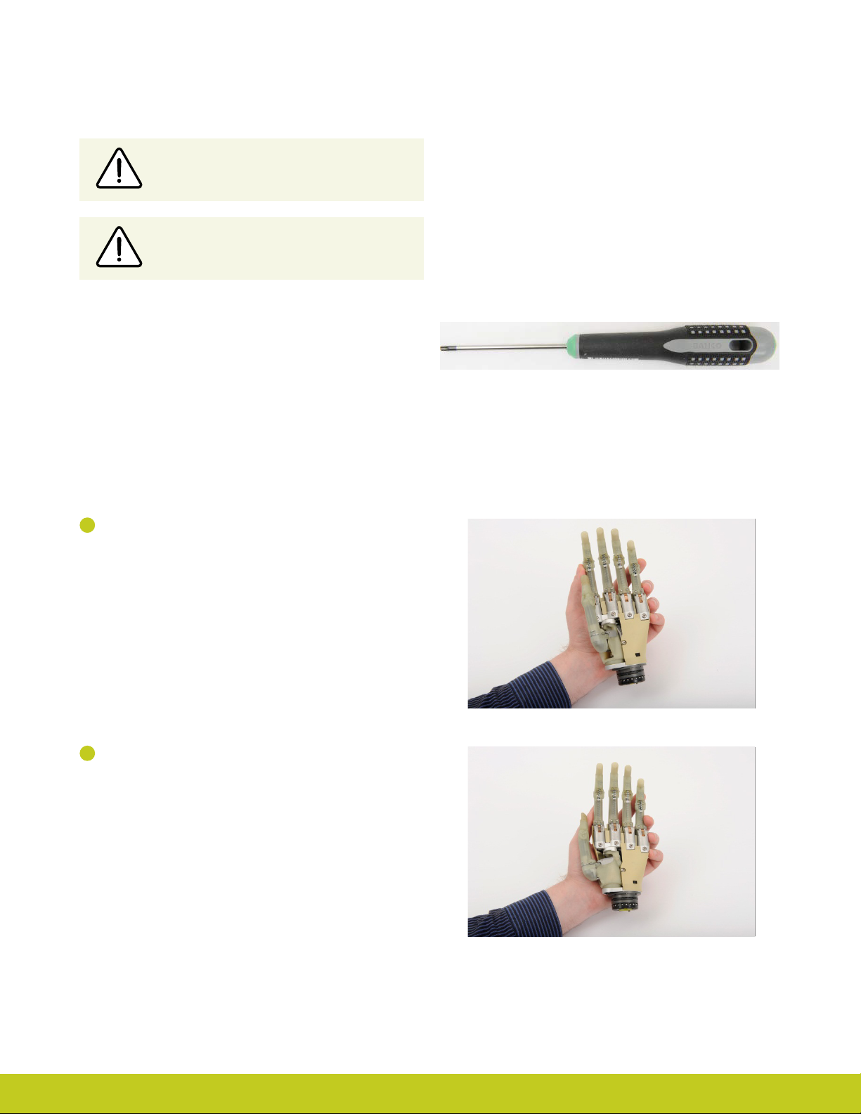
4.3 Thumb Installation
The i-limb select is only compatible with Touch Bionics i-limb
select thumb digits. When exchanging a thumb, ensure the correct
size has been selected.
Instruments required: T10 Screwdriver provided by
Touch Bionics.
1
Support the i-limb select in the palm of the hand.
2
Fully rotate the thumb to the side as illustrated.
Part number: MA 01155 Issue No. 4, January 2015
Page 24
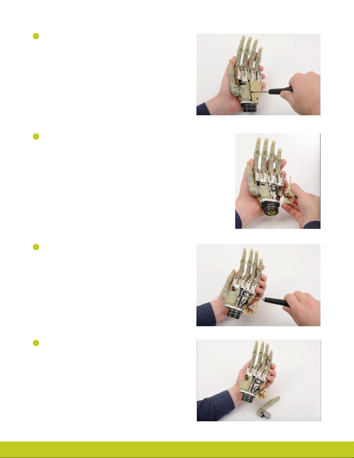
3
Disconnect the Palm Fairing using the T10 screwdriver to
loosen the palmar T10 screw.
4
Gently move the Palm Fairing to the ulnar side to allow
access to the exposed T10 screw at the base of the thumb.
5
Using the T10 Screwdriver access the screw from the
medial to lateral direction to loosen.
6
The thumb is now easily removed from the knuckle block.
Part number: MA 01155 Issue No. 4, January 2015
24 of 50
Page 25
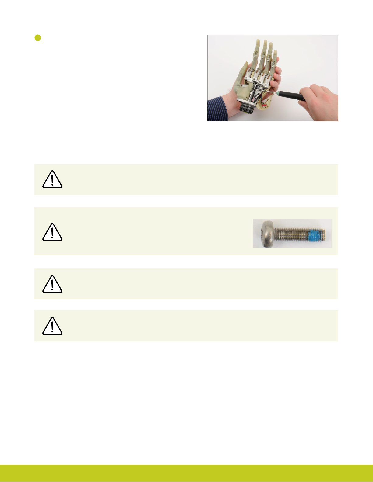
7
Position the replacement thumb in the knuckle block and
follow the above steps in reverse order to reconstruct the
hand. When replacing the palm fairing, ensure wires are not
pinched between the palm fairing and the chassis.
It is recommended that you discard the used screws as the antivibration pad on the screw shaft will be deformed during use.
Digit screws should be replaced using the new screws provided.
Do not over tighten screws.
If there is resistance while tightening the screw check for cross threading
by removing and re-inserting the screw.
Touch Bionics recommends T10 Screwdriver for use with all T10 screws in the i-limb select.
Do not reuse screws
Part number: MA 01155 Issue No. 4, January 2015
Page 26
5.0 Covers
5.1 Cover Options
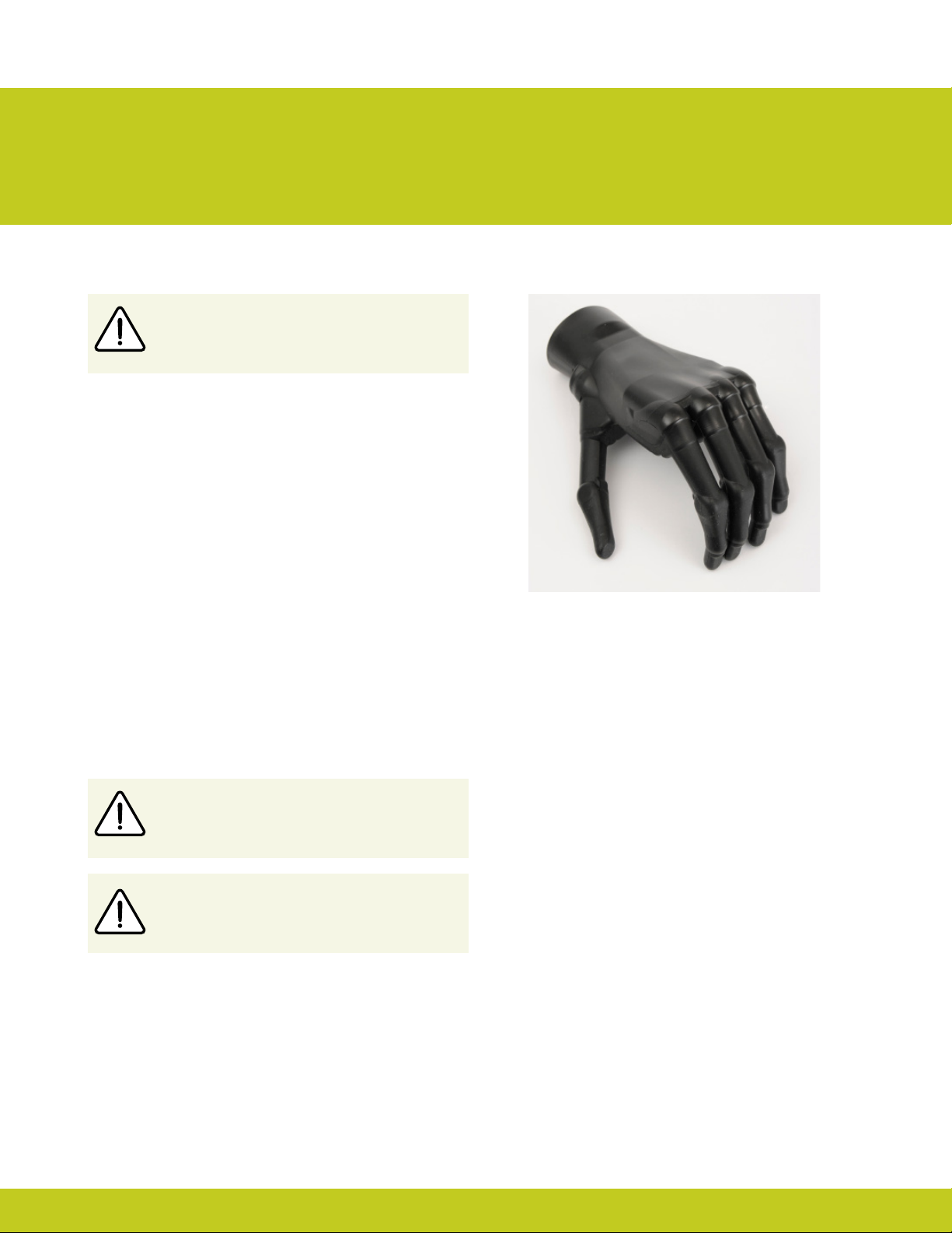
The cover of the i-limb select is very important.
The i-limb select can be used with both i-limb skin active and i-limb
skin natural covers. These covers require regular checks for wear
and tear. Covers will need occasional replacement depending
on level of use. Contact your distributor to purchase additional
covers.
The i-limb skin active cover is designed for the i-limb select
and will fully cover the hand. The palm and inner surface of the
cover provide some frictional properties for slip resistance when
gripping. The back of the glove is smooth to allow the hand to
easily move through sleeves of clothing.
Please consult the Coverings Care Guide for donning and dong
instructions as well as tips on wear and care. The Coverings Care
Guide can be found on our website at www.touchbionics.com/
downloads/document-library.
The i-limb select should not be used without an
approved cover that is well maintained.
Do not alter covers
Only use approved Touch Bionics covers. Covers
that are not approved will damage i-limb select
Part number: MA 01155 Issue No. 4, January 2015
26 of 50
Page 27
6.0 biosim app clinician version
6.1 biosim app overview
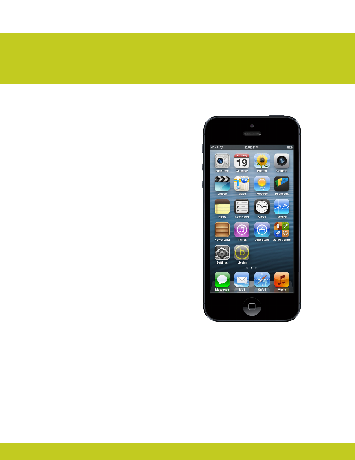
Welcome to the mobile world of Touch Bionics! The biosim
mobile application is provided for you to quickly and easily
change the features of the i-limb select prosthesis while on the
move.
Important points to note:
• The biosim mobile app must be downloaded from the
• Please ensure that you select the biosim app shown by the
• The iPod (sold separately) connects to your i-limb select via
• The biosim mobile App is compatible with the following
• To exit the application at any time, simply press the main
®
Apple
App store
grey and white logo
a Bluetooth connection, which is automatically established
when you start the biosim app
devices: iPhone® (4s or newer), iPad® (4th generation or newer),
iPad® mini, iPod® (5 or newer).
“Home” button on the front of your mobile device.
Part number: MA 01155 Issue No. 4, January 2015
Page 28
6.2 Getting started
For general instructions on using your iPod Touch (sold separately), read the
quick start guide provided by Apple in the packaging of your iPod Touch.
The rst time that you use the device you will need to be connected to
the Internet via the iPod’s Wi-Fi connection. You can connect to a Wi-Fi
network by tapping on the “settings” icon on the rst screen.
Next go to the App Store via the icon. Tap on it to start the app. To search
for the biosim app, type “Touch Bionics” or “biosim” in the search tab and
download the app to your iPod.
Note: an Apple ID will be required to down load the app. If you do not have
one , please create an account by logging on to the Apple website or using
another mobile device.
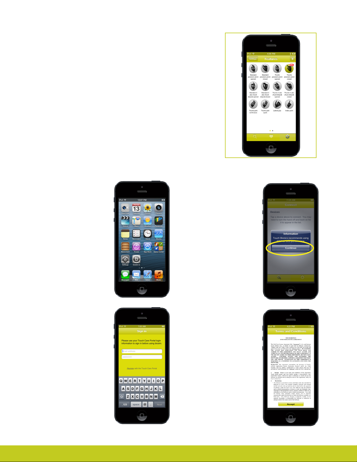
After installation of
biosim
Upon downloading the biosim
mobile app, an icon will appear
on your iPod screen. Tap on it
to start the app.
Activation
The rst time you connect to
biosim, you will see the “Sign
in” screen. Here you will need
to enter the email address and
password that you use when
you log-in on the Patient Care
Pathway on Touch Bionics’ web
site. If you need to create an
account, you may also do so
by selecting “Register” on the
screen shown.
Note
Touch Bionics recommends
using the latest Apple iOS for
best performance. If you are
using an older version of iOS,
you may receive a one-time
notice. Tap “Continue” to
acknowledge.
Activation
You will need to activate
your account by conrming
the email sent to the email
account you provided prior to
being able to connect. Upon
registering, please review the
Terms and Conditions. Tap
“Accept“ to continue.
Part number: MA 01155 Issue No. 4, January 2015
28 of 50
Page 29
Firmware Updates
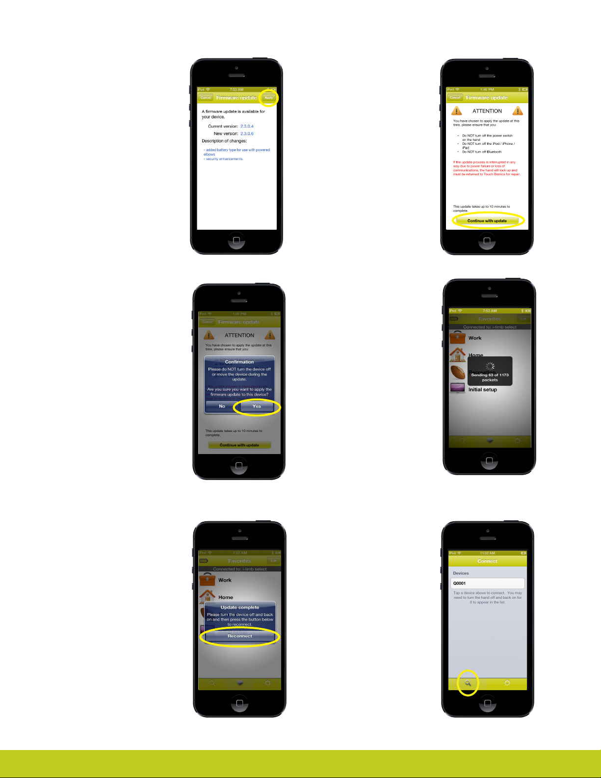
Touch Bionics‘ always
recommends that you download
the latest rmware for your
device. If a rmware update is
available, you will be prompted
with the following screen upon
connection to biosim.
Tap "Apply“ to initiate the
update. Tapping "Cancel“ will
dismiss this screen.
Firmware Updates
Tapping "Apply“ will bring you
to the rmware update warning
screen. Ensure you read and
comply with all warnings. Tap
"Continue with update" to
proceed.
Note: Ensure that you are able
to perform the update without
interruption. Loss of power or
hand communication could
result in your device locking,
which will require service by
Touch Bionics. Total update time
may take up to 10 minutes.
After tapping "Continue with
update" you will arrive at a nal
conrmation screen. Tap "Yes"
to continue.
At the conclusion of the update
you will be prompted to turn
your device o and back on
again to complete the update.
After powering o and on, tap
"Reconnect" to continue using
the biosim app.
After tapping "Yes" the update
will begin. You will see a
variety of screens as the update
progresses. Update screens
may vary depending on device
updated.
Connection
After signing in, you will be
brought to the connection
screen where you will tap your
device to connect.
Searching for another
device
Tap the search icon to
disconnect from the current
hand at any time and search
for a dierent hand. You will be
prompted to conrm.
Part number: MA 01155 Issue No. 4, January 2015
Tap No to return to the app
Tap Yes to disconnect.
Page 30
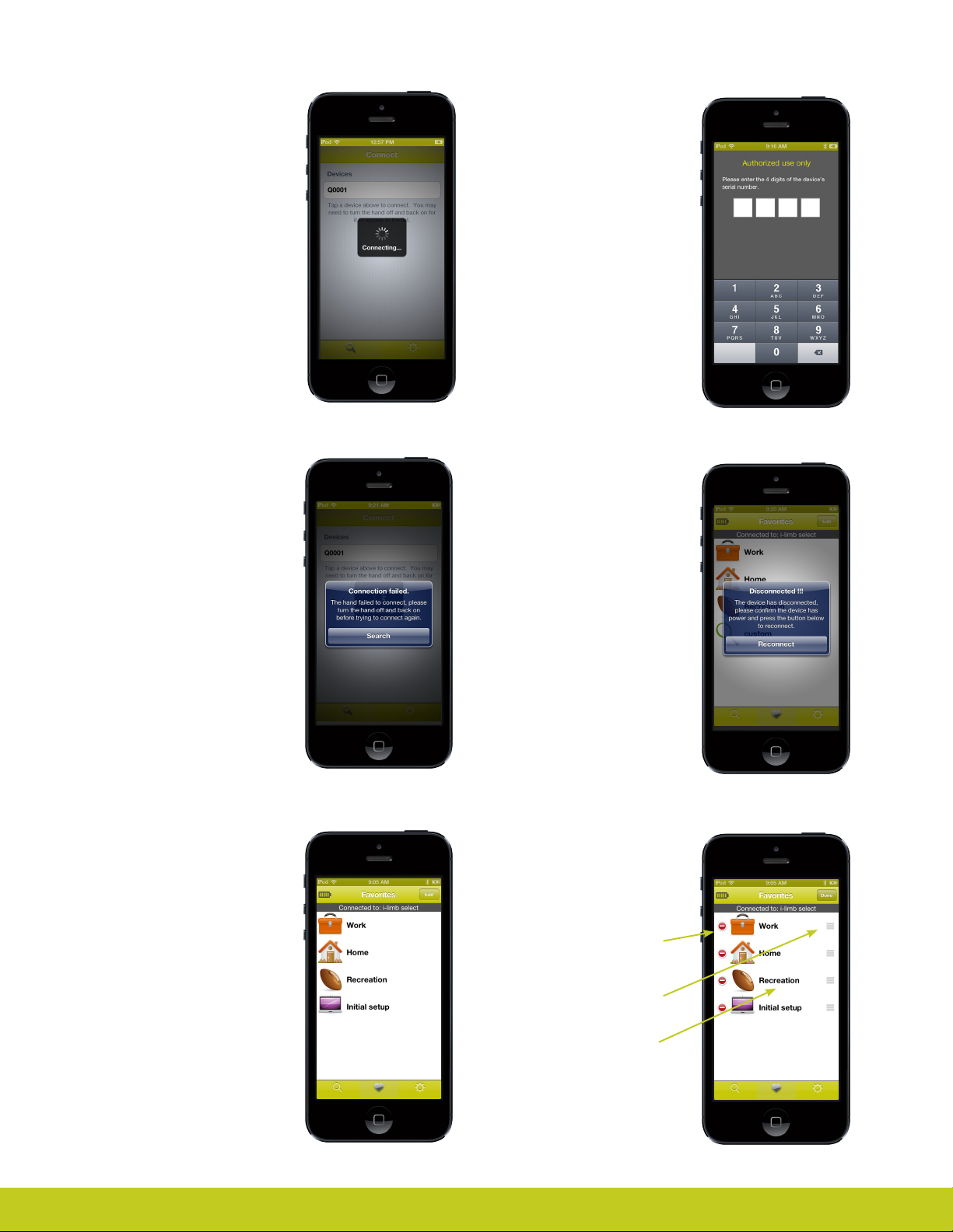
Connection
When hand is turned on and
ready to connect, the screen
will show this display
Tap on the desired device
serial number to begin the
connection process.
Authorized User Access
In order for you to connect to a
patient’s device, they will need
to tell you their 4 digit serial
number located proximal to
the base of the thumb on the
connection plate. You will be
prompted to enter this after
selecting the patient’s device.
Connecting
If the app is unable to connect
to the selected hand, the
screen at the right will appear.
Turn the hand o and back on,
then make sure the hand is
functional.
Tap search to try again
Favorites
Here you can assign groups
of grip patterns and triggers a
single name to make them easily
accessible with a single tap.
Accidental
disconnection
If the hand should disconnect
from the app due to loss of
power or proximity with the
i-pod/phone the screen at the
right will appear:
Tap Reconnect to re-establish
the connection
Editing favorites
Tap the edit button at the top
right and the screen changes
to look like the one at the right
Tap the red symbol to delete
the favorite
Part number: MA 01155 Issue No. 4, January 2015
Grab the handles and drag to
re-order the list
Tap the name of the entry to
edit the favorite
30 of 50
Page 31
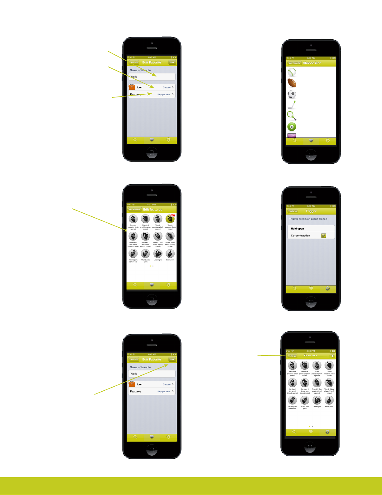
Editing favorites
Tap here to change the name
Tap here to change the icon
associated with the favorite.
Tap here to change the features
and triggers that will be sent to
the hand when this favorite is
activated from the favorite list.
Editing favorites
Tap an icon to choose one to
associate with the favorite you
are editing.
Editing favorites
Tap a feature to change its
trigger and options if available
Editing favorites
Once all changes have been
made use the top left button
to navigate back to the screen
at the right.
Editing favorites
Edit the trigger associated
with the previously tapped
feature.
Tap a trigger to change the
association.
Tap the edit features button in
the top left to return to the list
of features
Save a new favorite
To save a new favorite with the
currently active features and
triggers, tap the + button.
Tap the Save button to
permanently store the
changes in the list of favorites.
Favorites are not stored in the
hand, only within the app.
Part number: MA 01155 Issue No. 4, January 2015
Page 32
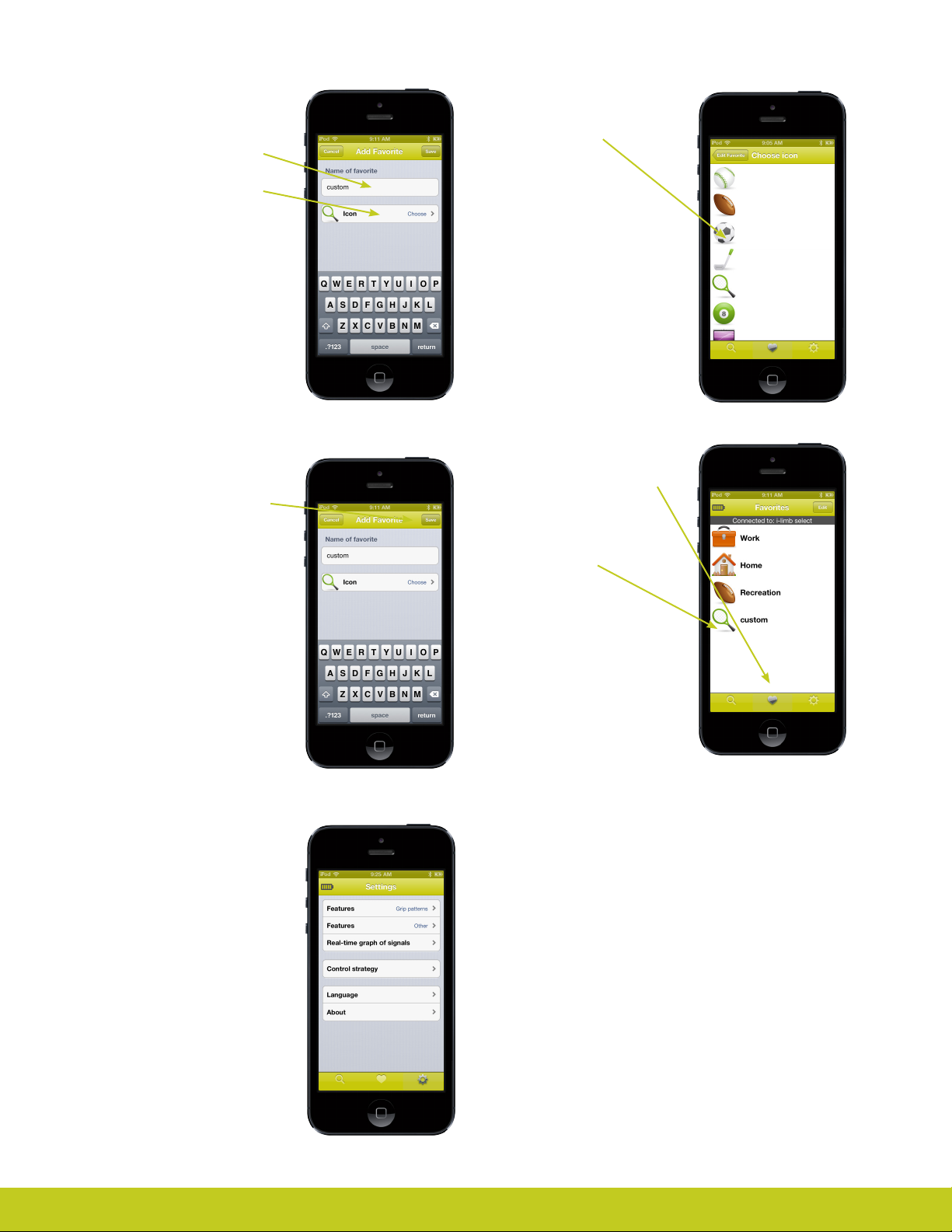
Save a new favorite
Tap the text eld to type in a
name for the new favorite
Tap the Icon entry to choose an
icon for the new favorite
Save a new favorite
Tap an icon to choose one for
the new favorite
Save a new favorite
Tap the save button to add the
new favorite to the list of all
favorites.
Can also tap the cancel button
to abort the creation of the
new favorite.
Currently active hand
settings
The settings pages present the
user with the currently active
hand conguration.
Save a new favorite
Switch to the favorites page by
tapping on the heart.
Notice the presence of the
new favorite created in the last
several slides.
Any changes made on the
settings pages are sent to
the hand and take eect
immediately.
Part number: MA 01155 Issue No. 4, January 2015
32 of 50
Page 33
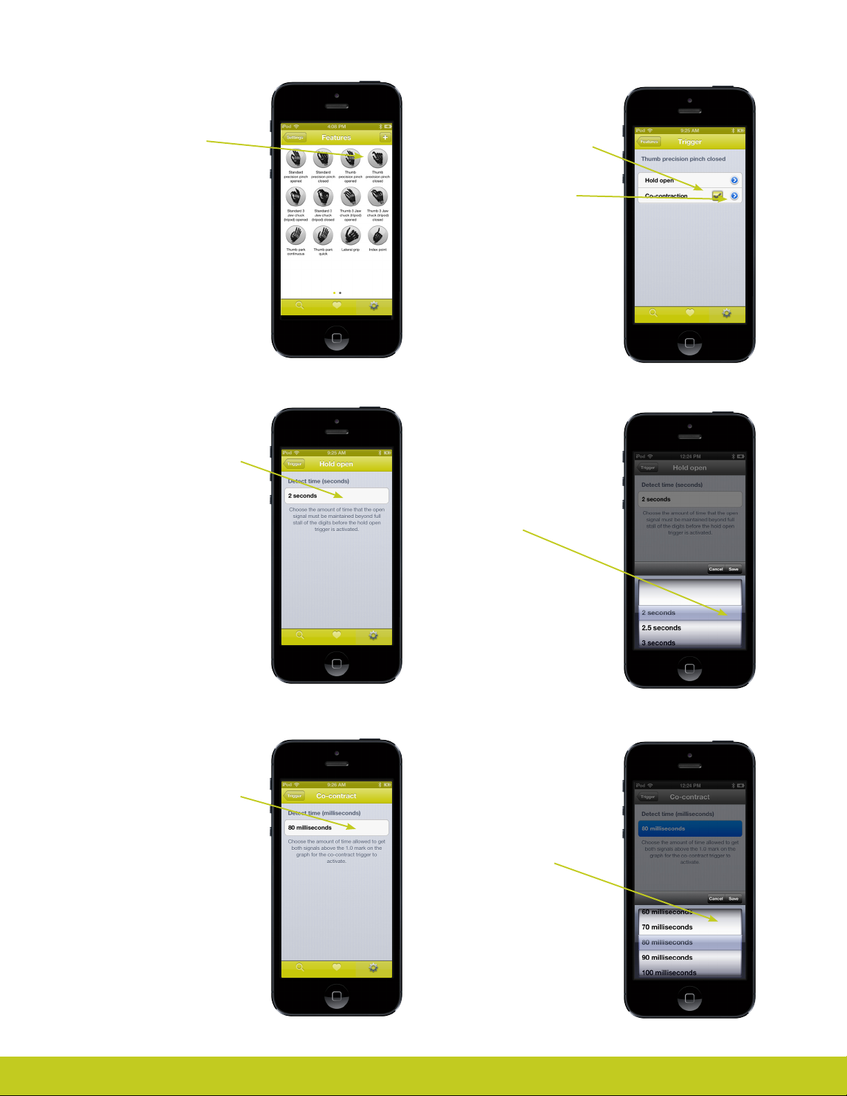
Currently active
features and triggers
Tap a feature icon to change
its trigger association.
Currently active
features and triggers
Tap a trigger to change its
association with the selected
feature
Tap the disclosure triangle
to adjust the settings for a
specic trigger
Currently active
features and triggers
Set the hold open detect time
by tapping the existing value
Currently active
features and triggers
Set the co-contract detect time
by tapping the existing value
Currently active
features and triggers
Use the spinning selection dial
to choose a new value and
tap the Save button.
Tap cancel to keep the current
value.
Currently active
features and triggers
Use the spinning selection dial
to choose a new value and
tap the Save button.
Part number: MA 01155 Issue No. 4, January 2015
Tap cancel to keep the current
value.
Page 34
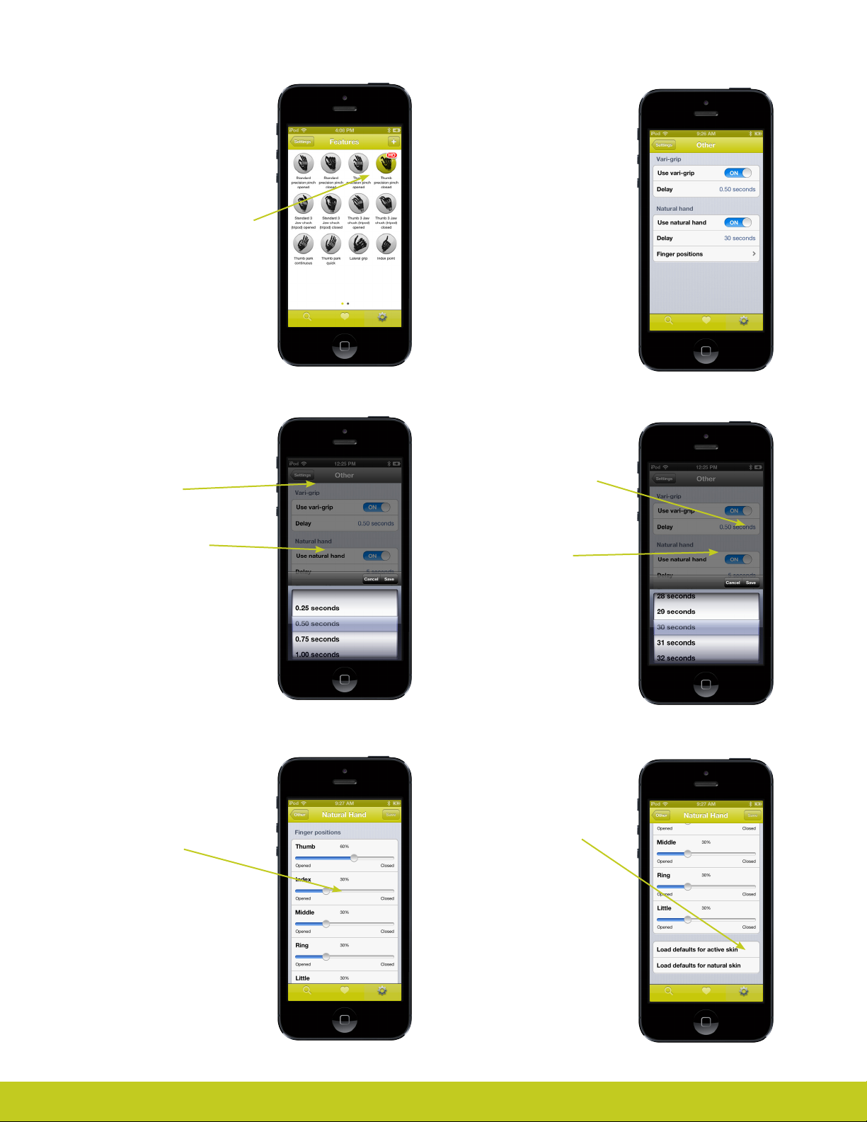
Currently active
features and triggers
This is an example of the
features page after the changes
from the previous page.
Notice the highlighted feature
with the trigger name under it.
This indicates the Hold Open
trigger will cause the hand to
enter the Thumb precision pinch
Other features
This page can be used to
enable or disable the various
global features of the hand.
Currently active
features and triggers
Tap the current vari-grip delay
setting.
Use the spinning selection dial
to choose a new value and
tap the Save button.
Tap cancel to keep the current
value.
Currently active
features and triggers
Use the sliders to adjust how
far open or closed the ngers
should be when natural hand
mode activates.
Tap the current natural hand
nger position entry.
Currently active
features and triggers
Tap the current natural hand
delay setting.
Use the spinning selection dial
to choose a new value and
tap the Save button.
Tap cancel to keep the current
value.
Currently active
features and triggers
Scroll down the page to reveal
entries that will set all the
ngers to default values.
Tap Other to keep the current
values.
Use the sliders to choose nger
positions and tap the Save
button.
Tap Other to keep the current
values.
Part number: MA 01155 Issue No. 4, January 2015
34 of 50
Page 35
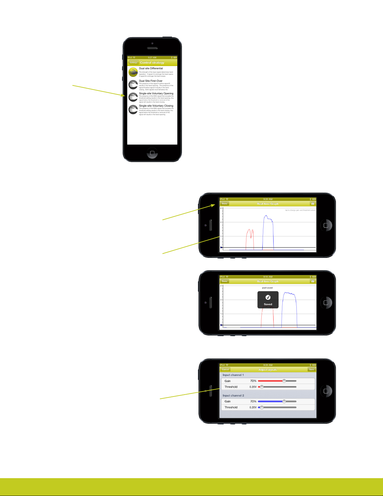
Change control
strategy
The highlighted icon indicates
the current control strategy.
Tap the desired control strategy
to change it.
Real time graph
The real time graph is best viewed in landscape mode
by rotating the device horizontally.It will show the
user’s input signals. Red for the open signal and blue
for the close signal.
Rotate the device to portrait mode or tap the Done
button to exit the graph.
Tap the camera button to save a snap shot to the
camera roll. Use the swipe gestures to scroll the
graph backwards and forwards to review up to 2
minutes of history.
Real time graph
Tapping on the real time graph will let you change
the gain and threshold settings.
Adjust the sliders to make changes. Red for the
open signal and blue for the close signal.
Tap the Save button to commit the changes or tap
cancel to return to the real time graph.
Part number: MA 01155 Issue No. 4, January 2015
Page 36
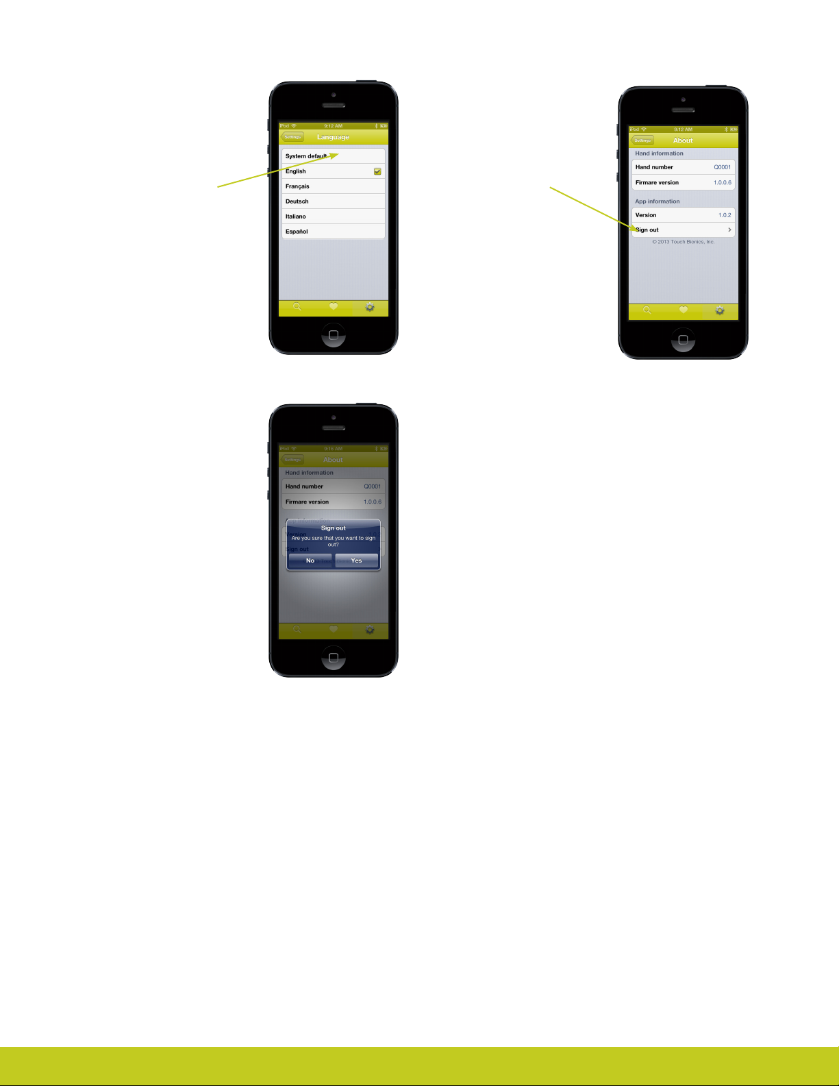
Multilingual support
Choose which language
should be used by the app.
About the App
This screen gives information
about the hand and the app.
Choosing system default will
make the app use whatever
language the rest of the
iPhone is using.
Signing out
You will be prompted to
conrm the sign out choice as
this cannot be undone.
Tap No to return to the app
Tap Yes to sign out.
Tap sign out to disconnect the
app from the PCP account you
are currently logged into.
Part number: MA 01155 Issue No. 4, January 2015
36 of 50
Page 37
7.0 my i-limb patient version
7.1 my i-limb Overview
Welcome to the mobile world of Touch Bionics! The my i-limb
mobile application is provided for you to quickly and easily
change the features of the i-limb select prosthesis while on the
move.
Important points to note:
• The my i-limb mobile app must be downloaded from the
• Please ensure that you select the my i-limb app shown by
• The iPod (sold separately) connects to your i-limb select via
• The my i-limb mobile app is compatible with the following
• To exit the application at any time, simply press the main
®
Apple
App store
the grey and white logo
a Bluetooth connection, which is automatically established
when you start the my i-limb app
devices: iPhone® (4s or newer), iPad® (4th generation or newer),
iPad® mini, iPod® (5 or newer).
“Home” button on the front of your mobile device.
Part number: MA 01155 Issue No. 4, January 2015
Page 38
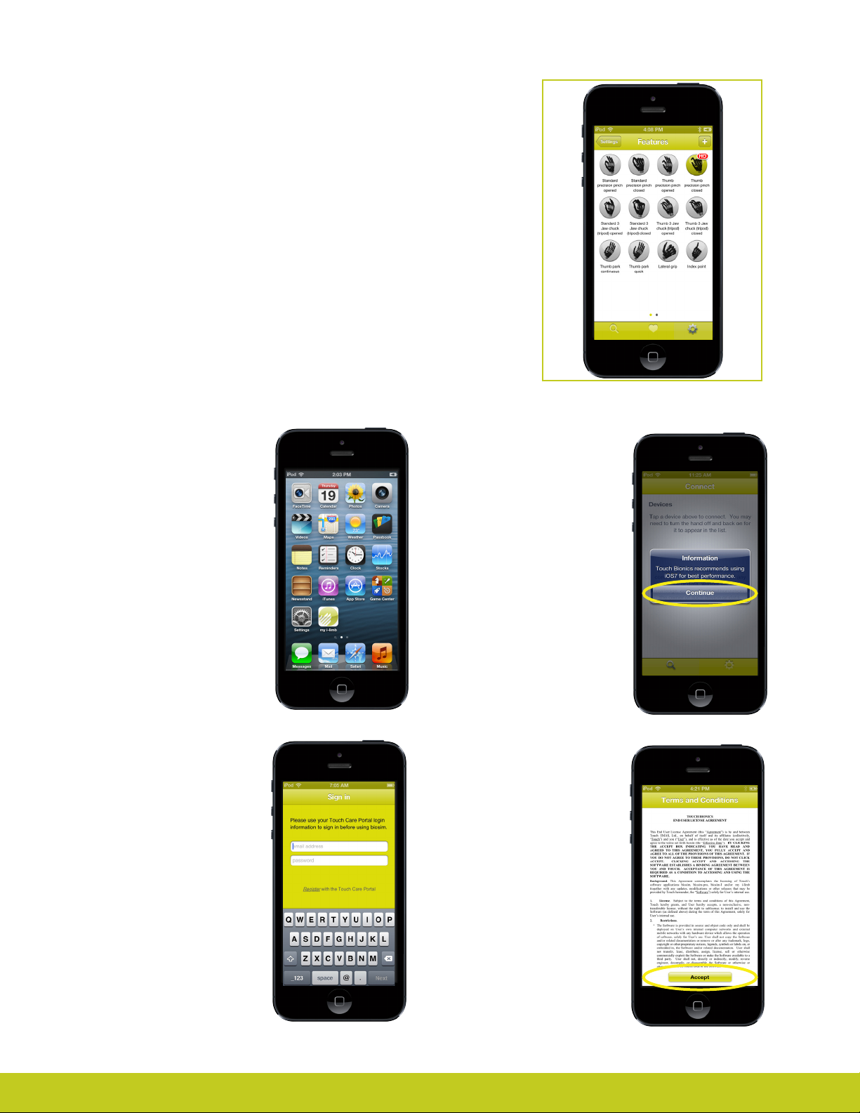
7.2 Getting started
For general instructions on using your iPod Touch (sold separately), read the
quick start guide provided by Apple in the packaging of your iPod Touch.
The rst time that you use the device you will need to be connected to
the Internet via the iPod’s Wi-Fi connection. You can connect to a Wi-Fi
network by tapping on the “settings” icon on the rst screen.
Next go to the App Store via the icon. Tap on it to start the app. To search
for the my i-limb app, type “Touch Bionics” or “my i-limb” in the search tab
and download the app to your iPod.
Note: an Apple ID will be required to down load the app. If you do not have
one, please create an account by logging on to the Apple website or using
another mobile device.
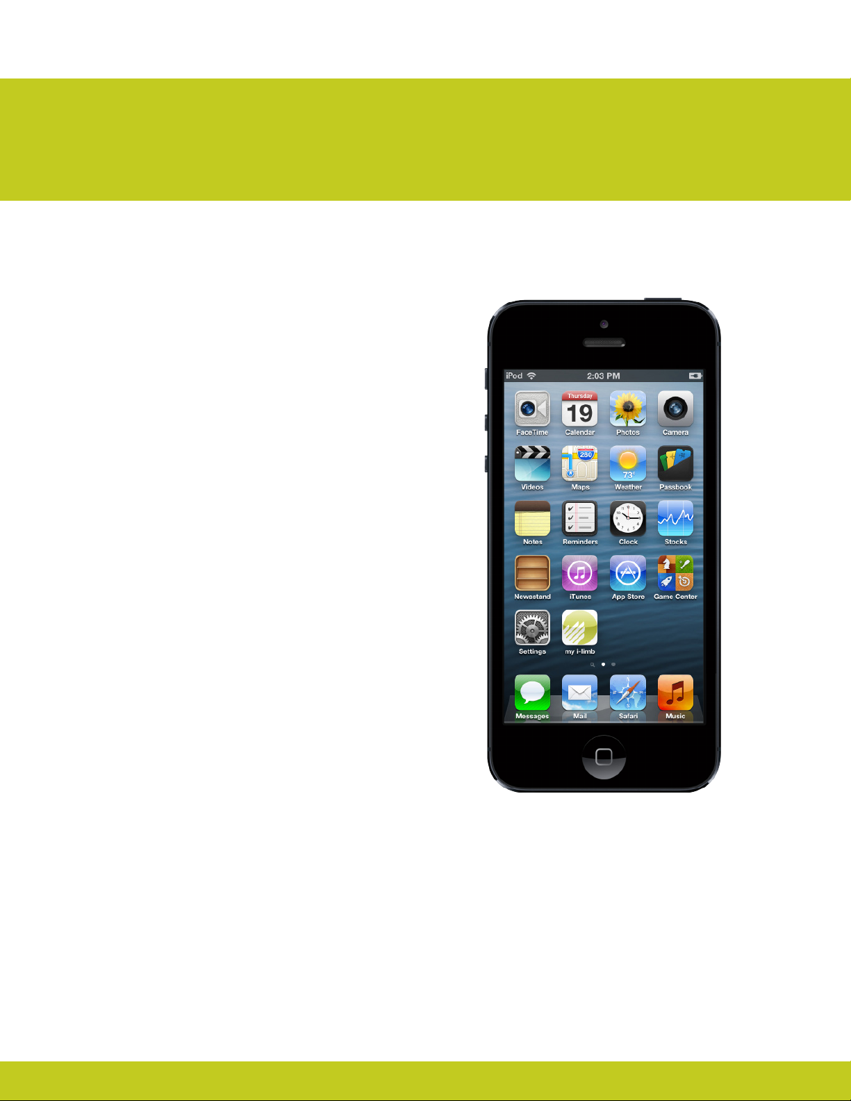
After installation of
my i-limb
Upon downloading the my
i-limb mobile App, an icon will
appear on your screen. Tap on it
to start the app.
Activation
The rst time you connect to
my i-limb, you will see the “Sign
in” screen. Here you will need
to enter the email address and
password that you use when
you log-in on the Patient Care
Pathway on Touch Bionics’ web
site. If you need to create an
account, you may also do so
by selecting “Register” on the
screen below.
Note
Touch Bionics recommends
using the latest Apple iOS for
best performance. If you are
using an older version of iOS,
you may receive a one-time
notice. Tap “Continue” to
acknowledge.
You will need to activate
your account by conrming
the email sent to the email
account you provided prior to
being able to connect. Upon
registering, please review the
Terms and Conditions. Tap
“Accept“ to continue.
Part number: MA 01155 Issue No. 4, January 2015
38 of 50
Page 39
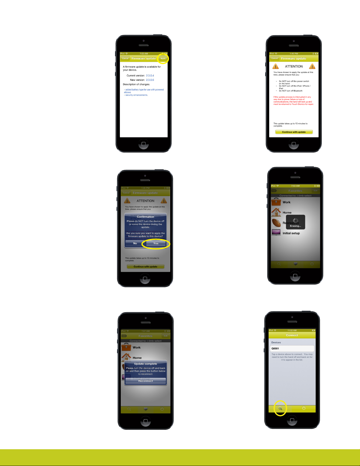
Firmware Updates
Touch Bionics‘ always
recommends that you download
the latest rmware for your
device. If a rmware update is
available, you will be prompted
with the following screen upon
connection to biosim.
Tap "Apply“ to initiate the
update. Tapping "Cancel“ will
dismiss this screen.
Firmware Updates
Tapping "Apply“ will bring you
to the rmware update warning
screen. Ensure you read and
comply with all warnings. Tap
"Continue with update" to
proceed.
Note: Ensure that you are able
to perform the update without
interruption. Loss of power or
hand communication could
result in your device locking,
which will require service by
Touch Bionics. Total update time
may take up to 10 minutes.
After tapping "Continue with
update" you will arrive at a nal
conrmation screen. Tap "Yes"
to continue.
At the conclusion of the update
you will be prompted to turn
your device o and back on
again to complete the update.
After powering o and on, tap
"Reconnect" to continue using
the biosim app.
After tapping "Yes" the update
will begin. You will see a
variety of screens as the update
progresses. Update screens
may vary depending on device
updated.
Connection
After signing in, you will be
brought to the connection
screen where you will tap your
device to connect.
Searching for another
device
Tap the search icon to
disconnect from the current
hand at any time and search
for a dierent hand. You will be
prompted to conrm.
Part number: MA 01155 Issue No. 4, January 2015
Tap No to return to the app
Tap Yes to disconnect.
Page 40
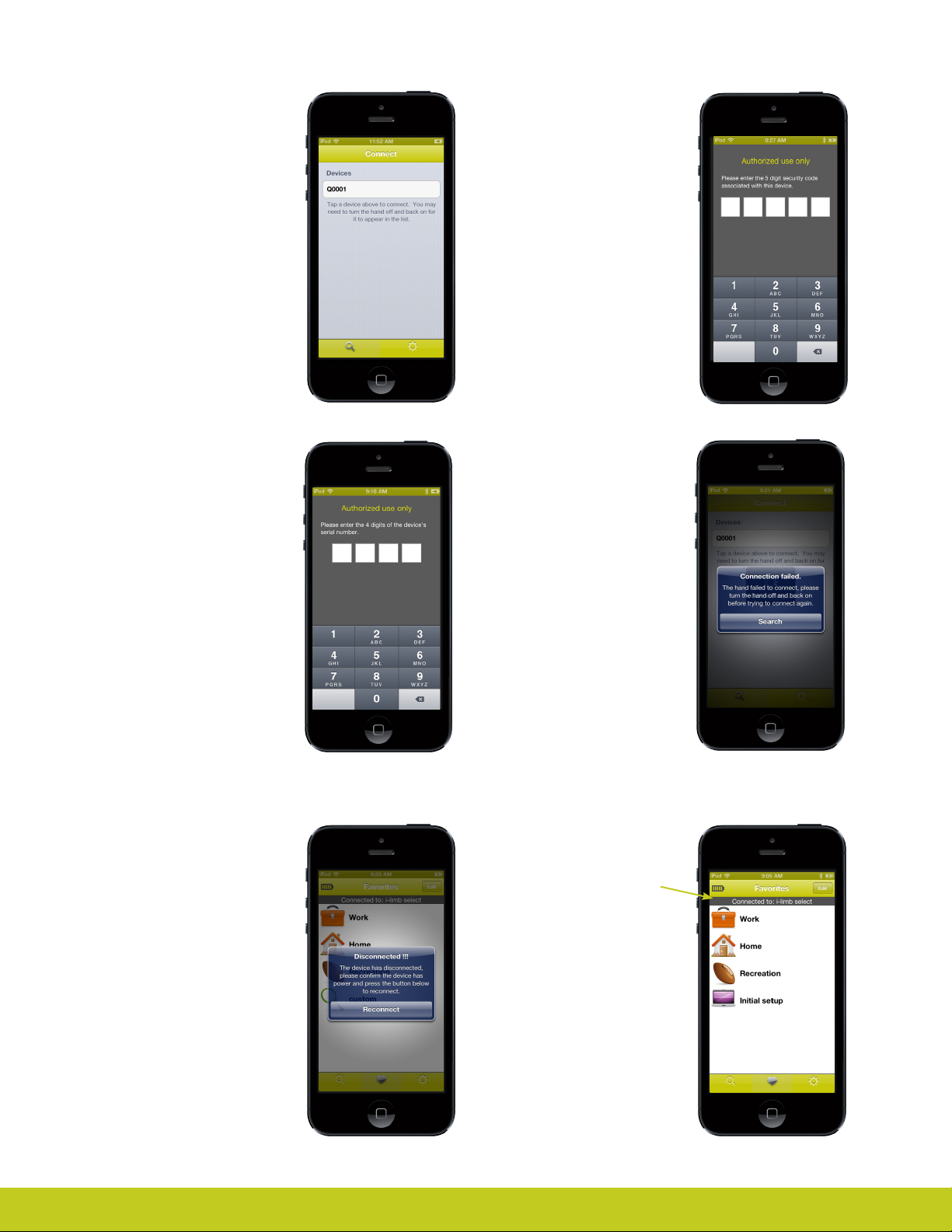
When the hand is turned on
and is ready to connect the
screen will show this display.
Tap the desired device to
begin connection process
Authorized User Access
In order for someone else to
gain access to your device you
will need to tell them your 5
digit security code. This unique
code can be found in the
“About“ section of the my i-limb
app discussed later. They will
be prompted to enter this after
selecting your device.
In order for a clinician to access
your device you will need to
tell them your 4 digit serial
number located on the wrist
plate near the thumb. They will
be prompted to enter this after
selecting your device.
Accidental
disconnection
If the hand should disconnect
from the app due to loss of
power or proximity with the
device the screen at the right
will appear.
If the app is unable to connect
to the selected hand, the screen
at the right will appear.
Turn the hand o and back on,
then make sure the hand is
functional.
Tap search to try again
Favorites
Here you can assign groups
of grip patterns and triggers
a single name to make them
easily accessible with a single
tap.
Tap Reconnect to re-establish
the connection
Part number: MA 01155 Issue No. 4, January 2015
40 of 50
Page 41
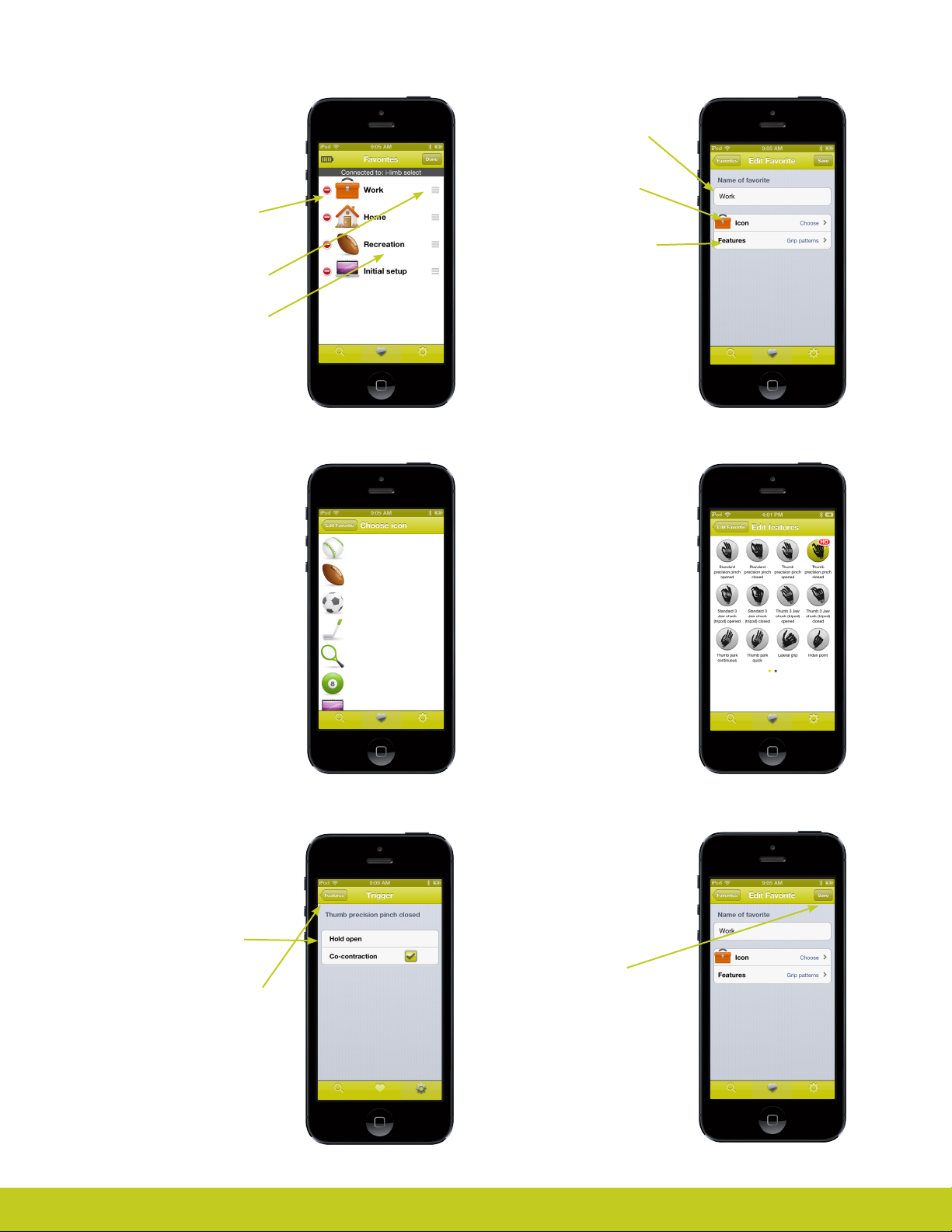
Editing favorites
Tap the edit button at the top
right and the screen changes
to look like the one seen here
to the right
Editing favorites
To change the name tap here
Tap here to change the icon
associated with the favorite.
Tap to red symbol to delete
the favorite
Grab the handles and drag to
change the order of the list
Tap the name of the entry to
edit the favorite
Editing favorites
Tap an icon to choose one to
associate with the favorite you
are editing.
Tap here to change the
features and triggers that will
be sent to the hand when this
favorite is activated from the
favorite list.
Editing favorites
Tap an icon to choose one to
associate with the favorite you
are editing.
Editing favorites
Edit the trigger associated
with the previously tapped
feature.
Tap a trigger to change the
association.
Tap the features button in the
top left to return to the list of
features
Part number: MA 01155 Issue No. 4, January 2015
Editing favorites
Once all changes have been
made use the top left button
to navigate back to the screen
at the right.
Tap the Save button to
permanently store the
changes in the list of favorites.
Favorites are not stored in the
hand, only within the app.
Favorites are device specic,
meaning you can have
dierent favorites for each
hand.
Page 42
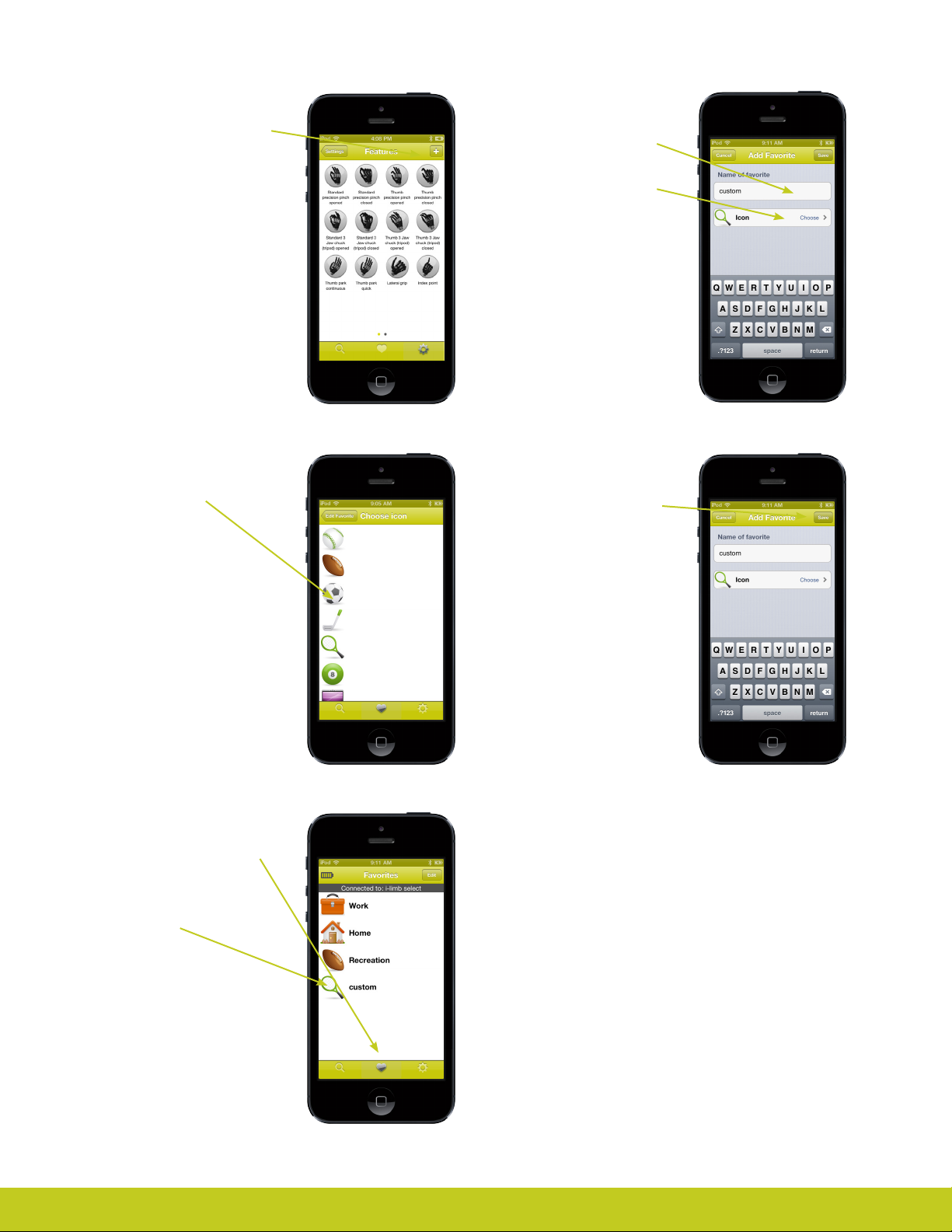
Save a new favorite
To save a new favorite with the
currently active features and
triggers, tap the + button.
Save a new favorite
Tap the text eld to type in a
name for the new favorite
Tap the Icon entry to choose an
icon for the new favorite
Save a new favorite
Tap an icon to choose one for
the new favorite
Save a new favorite
Switch to the favorites page by
tapping on the heart.
Notice the presence of the
new favorite created in the last
several slides.
Save a new favorite
Tap the save button to add the
new favorite to the list of all
favorites.
You can also tap the cancel
button to abort the creation of
the new favorite.
Part number: MA 01155 Issue No. 4, January 2015
42 of 50
Page 43
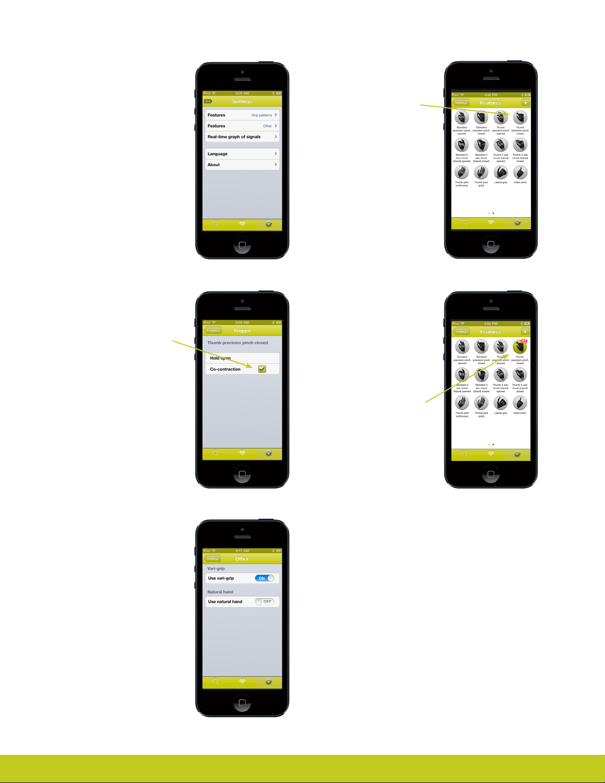
Currently active
features and triggers
The settings pages present
the user with the currently
active hand conguration.
Any changes made on the
settings pages are sent to
the hand and take eect
immediately.
Currently active
features and triggers
continued...
Tap a feature icon to change
its trigger association
Currently active
features and triggers
continued…
Tap a trigger to change its
association with the selected
feature
Other features
This page can be used to
enable or disable the various
global features of the hand.
Currently active
features and triggers
continued…
This is an example of the
features page after the
changes from the previous
page.
Notice the highlighted feature
with the trigger name under it.
This indicates the Hold Open
trigger will cause the hand
to enter the thumb precision
pinch closed feature.
Part number: MA 01155 Issue No. 4, January 2015
Page 44
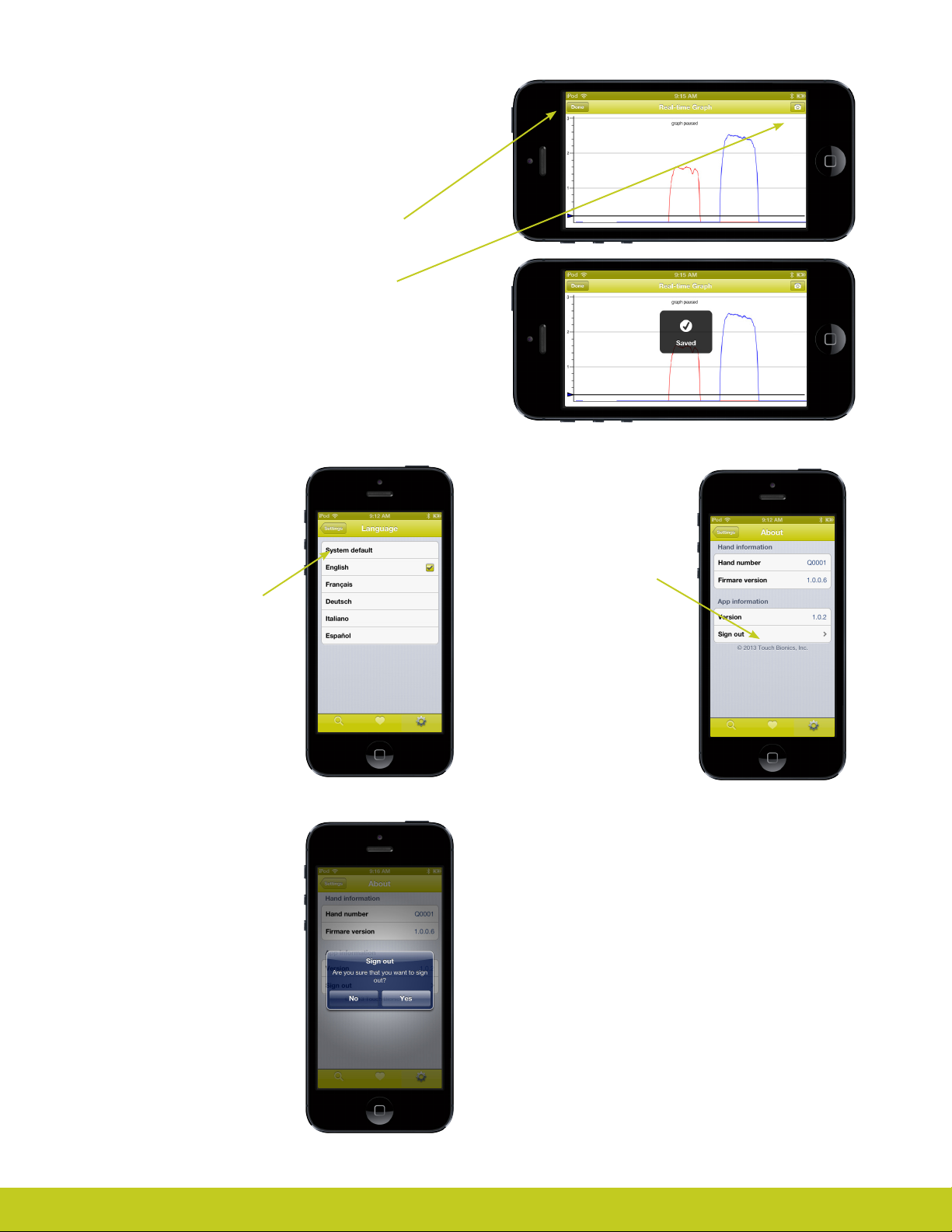
Real time graph
The real time graph will show the user’s input signals
and is best viewed in landscape mode. It shows red
for the open signal and blue for the close signal.
Rotate the device to portrait mode or tap the Done
button to exit the graph.
Tap the camera button to save a snap shot to the
camera roll.
Use the swipe gestures to scroll the graph
backwards and forwards to review up to 2 minutes
of history.
Multilingual support
You can choose which
language should be used by
the app.
Choosing system default will
make the app use whatever
language the rest of the device
is using.
Signing out
You will be prompted to
conrm the sign out choice as
this cannot be undone.
Tap No to return to the app.
About the app
Gives information about the
hand and the app.
Tap sign out to disconnect
the app from the current PCP
account.
Tap Yes to sign out.
Part number: MA 01155 Issue No. 4, January 2015
44 of 50
Page 45

8.0 Support Information
8.1 General Safety,Warnings and Precautions
i-limb select
Do not use without an approved cover.
Do not use under water.
Do not use to operate heavy / industrial machinery.
Do not use with machinery with moving parts that may cause
personal injury or damage.
Users must comply with local regulations on the operation of
automobiles, aircraft, sailing vessels of any kind and any other
motorized vehicle or device.
Do not use for extreme activities that may cause injury to a
natural hand.
Do not expose to excessive moisture, liquid, dust, vibration or
shock.
Do not expose to high temperatures.
Do not expose to ames.
Do not use or expose to explosive atmospheres.
Do not disassemble componentry or modify in any way.
Maintenance, repairs and upgrades may only be performed by
qualied Touch Bionics technicians and technical partners.
Do not use with a damaged cover.
Damaged covers must be replaced or repaired by a qualied
Touch Bionics technician or technical partner.
Only approved Touch Bionics accessories and tooling may be
used with the i-limb select.
Do not use an i-limb device to operate your mobile device whilst it
is connected to a mains outlet, as this can aect EMG signal.
Failure to comply with the above guidelines will invalidate the
warranty.
Batteries
Do not bend or exert excessive pressure on the battery.
Do not pierce the battery.
Do not disassemble.
Do not expose to high temperatures.
Do not incinerate batteries.
Do not alter battery terminal wires.
Do not short circuit the battery.
Do not store batteries inside a vehicle.
Dispose of batteries in accordance with local regulations.
Only use the appropriate Touch Bionics charger to charge
Touch Bionics batteries.
If the battery has visibly ballooned or swelled:
• discontinue the charging process immediately
• disconnect the battery
• remove to a safe area
• leave and observe for 15 minutes
• replace with new battery
• do not re-use
• dispose of any leaking batteries in an appropriate manner
Failure to comply with the above guidelines will invalidate the
warranty.
Part number: MA 01155 Issue No. 4, January 2015
If you experience technical problems with the i-limb select
contact your local distributor
Page 46

8.2 Troubleshooting
Problem
Hand does not
operate
One digit does not
operate
Hand stops halfway
during an action
User complains that the
hand is dicult to operate
Battery charge does not last
a full day
The hand will open but
not close
Hand opens when a close
signal is provided
Actio
n
Ensure the hand is switched on
Ensure the battery is connected
Ensure the battery is charged
Ensure the hand is engaged at the wrist
Check the electrodes have good contact
Check that the electrode cable is installed correctly (grey side out)
Exchange digit with an alternative working digit from same or dierent i-limb
select and re-check. If replaced digit works, contact your distributor
Electrode settings may need to be adjusted
Check the electrode cable is not damaged
Check the battery cable is not damaged
Check that the i-limb select is connected correctly to the wrist
Contact your local distributor
Electrode settings may be too low
Ensure the battery has good charge
Ensure the electrodes maintain good contact
Check electrode placement and wiring
Contact your local distributor
Fully charge the battery overnight. Check the battery connection
Ensure electrodes are not set above 5.5
Check user is not holding a sustained signal to the hand
Replace the battery
Contact your local distributor
Check that the electrode cables are attached are making good contact
Check the hand is engaged at the wrist
Check electrode operation by swapping the electrode connections at the lamination ring
Contact your local distributor
Reverse the connections at the lamination ring
Battery is not working Check the battery is connected
Part number: MA 01155 Issue No. 4, January 2015
Check the battery is charged
Check the wiring for signs of damage
Ensure that the charging port is not compressed by the inner and outer socket interface
Ensure the male connector from the charger is fully inserted into the charger port
Ensure that the connection between charger lead and port is good
46 of 50
Page 47

Driving of Motor Vehicles
The i-limb device has the functional capability to assist a patient with driving a motor vehicle however due
to factors including the dierences in world-wide driving regulations and the variations in the level of ability
between patients Touch Bionics is unable to provide denitive advice in respect to a patient with an i-limb
device driving a motor vehicle.
Touch Bionics is aware that patients have used the i-limb to drive a motor vehicle and our recommendations
prior to a patient doing so would include the following:
• contacting the driving authority in your home location to obtain and understand the local regulations;
• working with the appropriate authorities to have your car modied to meet the local regulations for your
respective disabilities as required;
• re-taking any mandatory driving test using your i-limb device to demonstrate your ability to operate a motor
vehicle safely if required by local regulations;
• contacting your insurance provider and advise them that you will be using the i-limb device to drive a motor
vehicle;
• ensuring that the device has a fully charged battery. Please note that the i-limb device will emit a low battery
signal which will alert you if the battery requires to be charged;
• moving the thumb into the lateral position and partially closing the ngers to allow the i-limb to be removed
from the steering wheel without opening the hand;
• switching o the i-limb device. This is due to the possibility of involuntary muscle signals being generated.
It is entirely the patient’s responsibility to seek conrmation that they are physically and legally able to drive using
the device and to the fullest extent permitted by law. Touch Bionics shall under no circumstances whatsoever be
liable to the patient or any other party as a result of or in connection with a patient with an i-limb device driving
a motor vehicle.
Part number: MA 01155 Issue No. 4, January 2015
Page 48

9.0 Appendix
9.1 Technical Information
i-limb select
Voltage 7.4 V (nominal)
Max. Current 5 A
Battery Capacity
Max hand load limit (static limit) 90kg/ 198lb
Finger carry load (static limit) 32kg/ 71lb
Time from open position to full power grip 1.2 seconds
Device Weight
9.2 i-limb select information
The i-limb select device is not intended for use outside the boundries of the environments listed below. The cus-
tomer or user of the i-limb select device should assure that it it not used in such environments
Condition Level
Maximum temperature
Rechargeable lithium polymer; 7.4 V (nominal);
1,300 mAh capacity
Weight with quick disconnect wrist 469g (small) and 479g (medium)
Hazardous Area Classication
+70˚c
Minimum temperature
Hazardous Area Classication
9.3 Component Compatibility
9.3.1 EMC and Electrical Information
Please refer to www.touchbionics.com/downloads/document-library for Electro Magnetic Compatibility (EMC) and Electrical
Information for i-limb products.
Part number: MA 01155 Issue No. 4, January 2015
-40˚c
Non-Hazardous
48 of 50
Page 49

9.4 Warranty
Limited Warranty for i-limb select
Touch Bionics warrants that the i-limb select will conform to its specications and be free of defects in material and/or
workmanship for twelve (12) months from the date of Touch Bionics invoice for the i-limb select. This Limited Warranty applies
only to an i-limb select provided by Touch Bionics or an aliate authorized by Touch Bionics to provide the i-limb select. This
Limited Warranty applies to all components including but not limited to xtures, motors, bearings, and electronics. This Limited
Warranty is governed by UK law and is not transferrable.
Warranty:
Touch Bionics reserves the right to credit, repair or replace an “in-warranty” i-limb select as its option. The wearer shall report
any defect claim directly or to the facility that provided the i-limb select immediately upon discovering the defect, and, in any event,
within the warranty period.
The defective i-limb select must be returned to your Practitioner/Supplier.
The unit must be in assembled condition and include an approved covering when returned. The warranty is void if the i-limb select
is subjected to abuse, neglect, alteration, modication, improper repair and/or maintenance performed by anyone other than Touch
Bionics or a Touch Bionics’ aliate.
Damage resulting from installation of parts and accessories not compatible with the i-limb select by anyone other than Touch Bionics
or an aliate is not covered, including use of non-Touch Bionics batteries. The warranty is void if damaged covers are not replaced
or repaired in a timely manner by a Touch Bionics cosmesis facility or another facility authorized by Touch Bionics, or if an approved
covering is not worn at all times when the i-limb select is being worn.
This is the exclusive remedy under this warranty, any and all other remedies that may otherwise be applicable are excluded,
including, but not limited to, incidental or consequential damage or punitive damage to the maximum extent permitted by law.
This is the only warranty made by Touch Bionics on the i-limb select and components, and there are no warranties which extend
beyond the description herein. Any warranties that may otherwise be implied by law including, but not limited to, any implied
warranty of merchantability or tness for a particular purpose are extended.
This Limited Warranty gives the consumer specic legal rights. The consumer may also have other legal rights which vary from
country to country. Some countries and states may not allow the exclusion or limitation of incidental or consequential damages
or warranties, so the above limitations or exclusions may not apply to you. If it is determined by a court of competent jurisdiction
that a certain provision of this limited warranty does not apply, such determination shall not aect any other provision of this limited
warranty and all other provisions shall remain in eect.
Part number: MA 01155 Issue No. 4, January 2015
Page 50
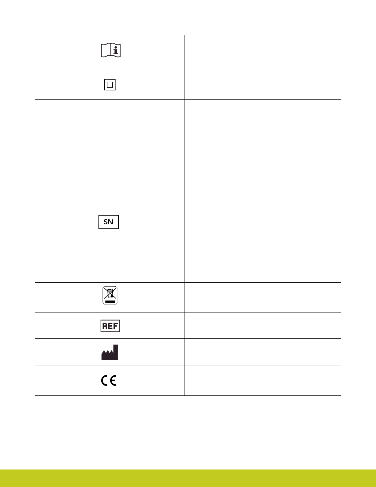
Consult instructions for use
Class II equipment – provides double Isolation to protect
against
Degree of protection – IP40
el
ectric sho
ck
IP40
Protection against penetration by solid particles with diameters
larger than 1 mm. No special protection against penetration by
water
Serial Number
For i-limb select devices:
The unique serial number for i-limb ultra revolution devices is a
“Q” with a 4 digit alpha / numeric number.
WEEE Compliance
Customer Service/Contact Information:
Touch Bionics, Unit 3 Ashwood Court, Oakbank Park Way, Livingston EH53 0TH , UK
Tel: Customer Service: +44 (0) 1506 438 556
Part number: MA 01155 Issue No. 4, January 2015
Catalogue nu
Manufacturer/Date of Manufacture
European Conformity
50 of 50
mber
Page 51

International Customers
Touch Bionics
Unit 3, Ashwood Court
Oakbank Park Way
Livingston EH53 0TH
Scotland
Tel: +44 1506 438 556
Email: [email protected]
For address details and further information
please visit www.touchbionics.com
Third party products and brand names
may be trademarks or registered
trademarks of their respective owners
© Copyright 2015 Touch Bionics Inc. and Touch Bionics Limited. All right s reserved.
MA 01155 Issue No. 4, January 2015
 Loading...