

touch bionics i-limb Clinician Manual
i-limbTM ultra revolution
Clinician Manual
Part number: MA01140: Issue No. 1, April 2013
This document provides instruction for prosthetists in the tting and servicing of the i-limb ultra revolution
and should be read in full prior to tting. It is highly recommended that the use of this manual is made in
conjunction with instruction from a clinician experienced in upper limb and myoelectric prostheses.
This symbol signies important information and is used throughout the manual.
A separate USB datadrive is included with your kit that contains all relevant product manuals.
You may also refer to www.touchbionics.com to ensure the latest copy of this document.
2

Table of Contents
1. i-limb ultra revolution 1.1 Product Description
1.2 Prosthesis Overview
2. Socket 2.1 Control Sites
2.2 Socket Fabrication
2.3 Charge Port Placement Assembly
2.4 Battery Options
2.5 Battery Conguration
2.6 Battery Installation
2.7 Battery Charging
3. Wrist 3.1 Wrist Connection Options
3.2 Quick Wrist Disconnect (QWD)
3.3 Wrist Disarticulation
3.4 Flex Wrist
3.5 Multi-ex Wrist
4. Adjustments 4.1 Digit Conguration
4.2 Digit Installation
4.3 Thumb Installation
5. Covers 5.1 Cover Options
5.2 Donning the i-limb skin active Cover
5.3 Dong the i-limb skin active Cover
5.4 Donning the i-limb skin natural Cover
5.5 Dong the i-limb skin natural Cover
5.6 Wear and Care Guidelines
6. biosim 6.1 biosim Overview
6.2 biosim Connecting
6.3 Navigating biosim
6.3.1 Myotesting
6.3.2 Control Strategy
6.3.3 Features
6.3.4 Training
6.3.5 Hand Health Check
6.3.6 Usage
6.3.7 Exit
7. Support Information 7.1 Storage and Maintenance
7.2 Troubleshooting
7.3 Warnings and Precautions
8. User Information 8.1 User Details
9. Appendix 9.1 Technical Information
9.2 i-limb ultra revolution Information
9.3 Component Compatibility
9.4 Warranty
Part number: MA01140: Issue No. 1, April 2013
3 of 57
1.0 i-limb ultra revolution
1.1 Product Description
The i-limb ultra revolution is an externally powered, multiarticulating prosthetic hand which oers a range of features
beyond the functions of the traditional prosthetic hand.
Individually motorized digits and thumb, stall detection and the
unique biosim software used to control the i-limb ultra revolution
result in the most versatile prosthetic hand currently available to
the global market.
Users can choose from a wide selection of automated grips and
gestures to help complete daily tasks. Grips and gestures can
then be customized further for precise control.
The i-limb ultra revolution oers compliant grip through individually powered digits with stall out ability. A powered rotating
thumb in conjunction with a pulsing, enhanced grip (vari-grip),
an anti-drop safety feature (auto-grasp) and the wide range of
automated grip patterns lead to broad functionality.
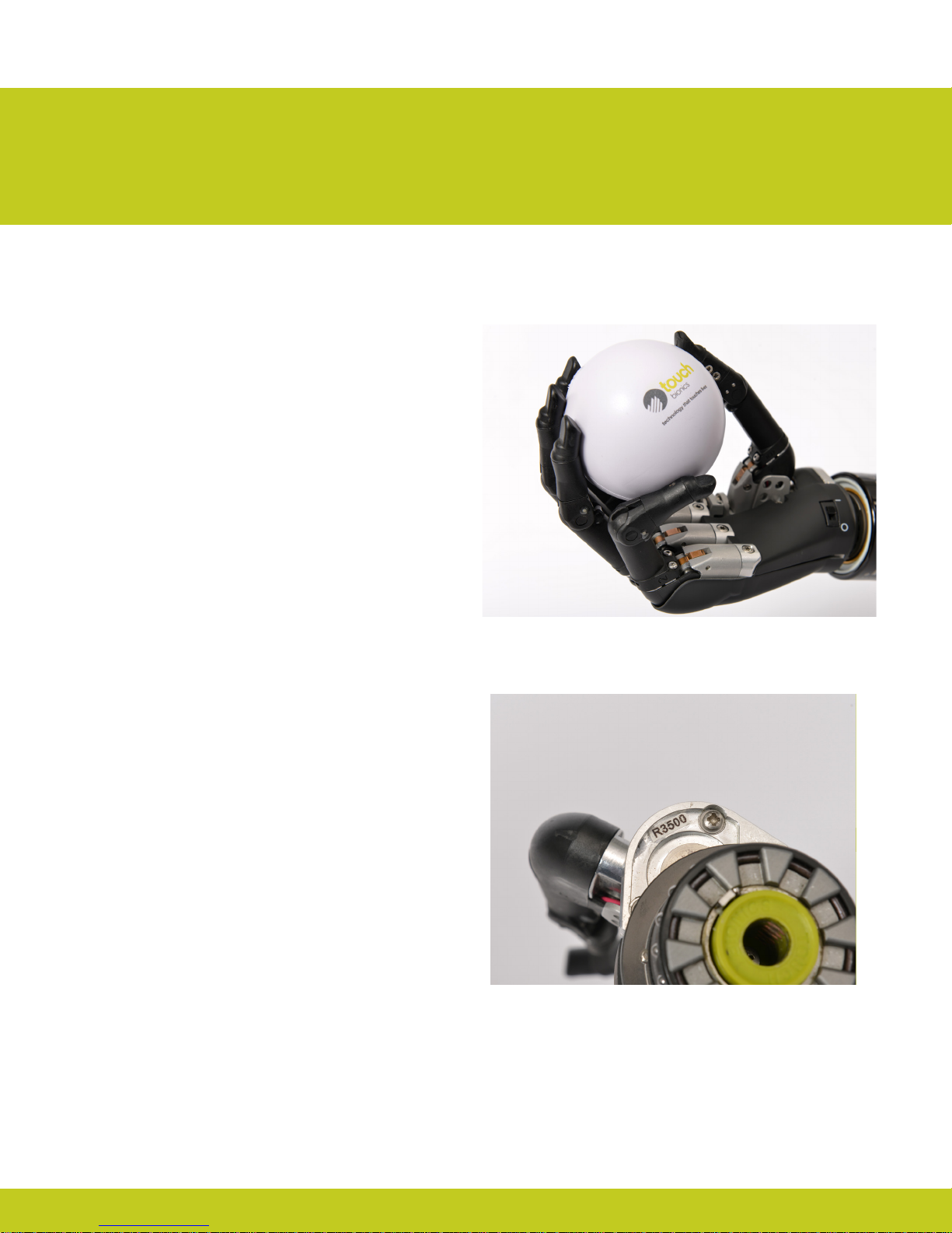
1.2 Prosthesis Overview
The i-limb ultra revolution is available in either black or neutral
colors, as well as small or medium sizes. The hand serial number is
positioned proximal to the base of the thumb on the connection
plate. The serial number should start with a “R” and be followed by
four numbers (also highlighted in biosim, see section 6).
Part number: MA01140: Issue No. 1, April 2013
4 of 57
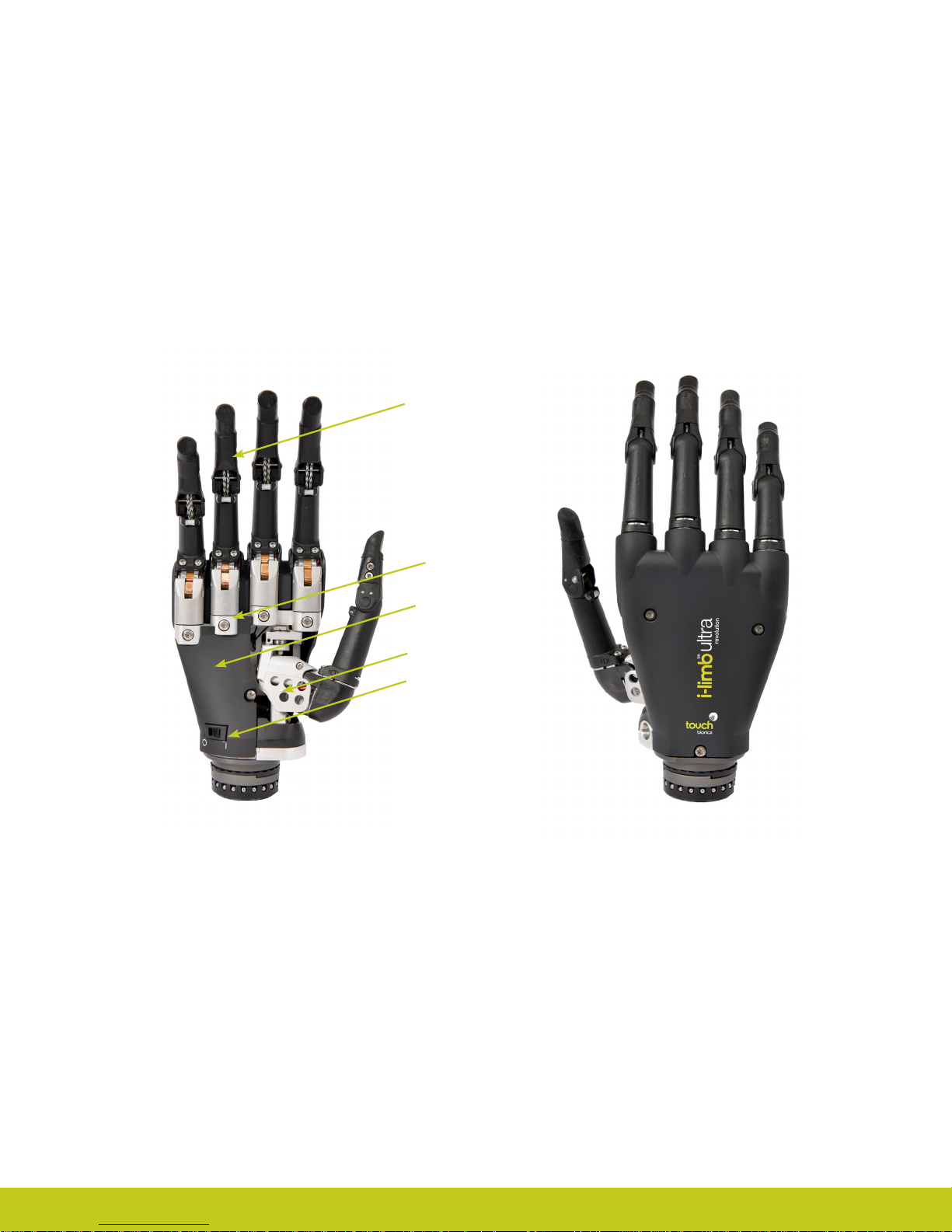
Motorized Digit
Knuckle
Palmar Fairing
Motorized Thumb
On / O Switch
Part number: MA01140: Issue No. 1, April 2013
2.0 Socket
2.1 Control Sites
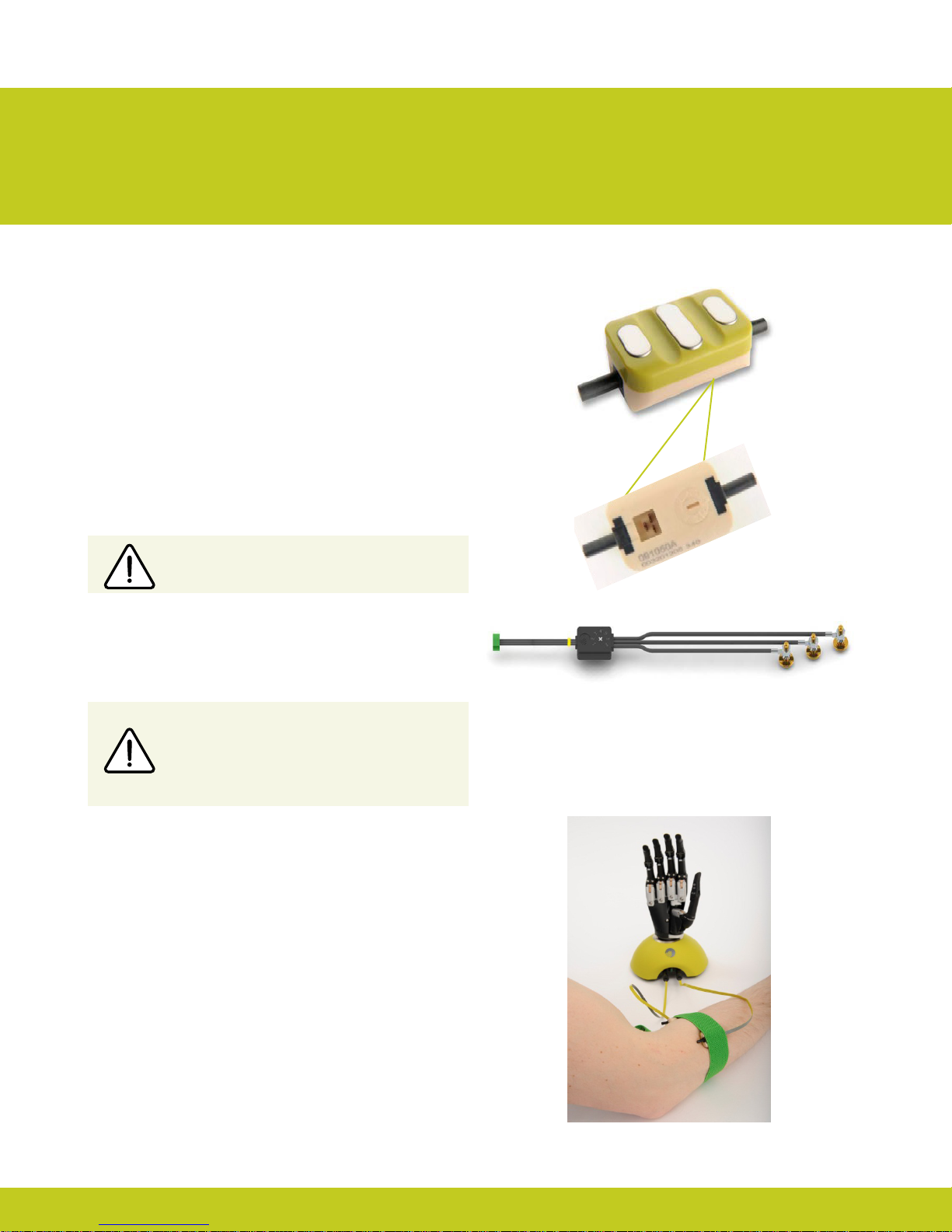
One option for control of the i-limb ultra revolution is electrodes.
There are two electrode options available for use with the i-limb
ultra revolution, compact electrodes (g. 1) or remote electrodes
(g. 2). For information regarding the tting of the Touch Bionics
Electrode, review the manual provided with the electrode.
Electrode Site Selection
The use of virtu-limb, the Touch Bionics’ myotesting system, is
recommended to determine the optimal placement of electrodes
(g. 3).
Consult Touch Bionics training materials for information on myotesting or section 6 of this manual for information on myotesting
within biosim.
Do not rely on previous myoelectrical testing.
Figure 1. Electrode Options
Figure 2. Remote Electrode
Use anatomical sites where the electrode will
maintain constant, even contact with the skin. Avoid
placing electrodes near socket interface trim lines,
bony areas, skin grafts or fatty tissue.
2.2 Socket Fabrication
While fabricating the socket for the i-limb ultra revolution, special
considerations will need to be given to:
1. Battery placement, size and conguration
2. Electrode position or other control method
3. Charge port placement
4. Socket length and the overall length of the prosthesis in
comparison to the opposite side.
Clinicians should have prior experience with building externally
powered prosthetic sockets before tting the i-limb ultra revolution.
Touch Bionics’ batteries, charger port and switch block components
should always be used with the i-limb ultra revolution.
Figure 3. virtu-limb
Part number: MA01140: Issue No. 1, April 2013
6 of 57
Socket Material
The use of Carbon ber is not recommended due to
electrical conductivity, if it is required to improve strength
then the carbon ber lamination must be grounded, if used
directly adjacent to electrodes (see Page 6). Please contact
Touch Bionics to order modied electrodes.
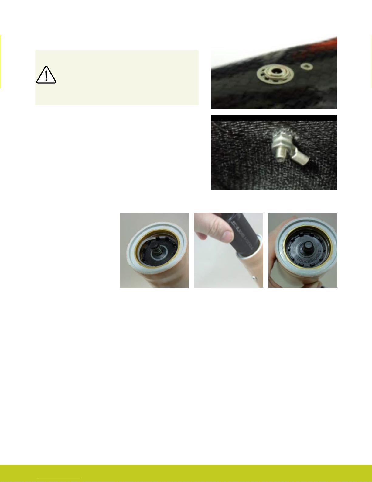
Coupling Piece Assembly
Insert the castelation ring (coupling
piece) into lamination ring and turn
until seated. Insert retaining ring
around outside edge of coupling
piece and use QWD release tool to
seat the retaining ring. The
QWD release tool is available to
order from Touch Bionics.
Please reference part number
PL091084 when ordering.
Part number: MA01140: Issue No. 1, April 2013

Battery Placement
Use Velcro™ to position the batteries on the pre-prepared
at surfaces to prevent distortion.
Battery Placement for a Long Residual Limb
Consideration of battery placement is particularly important
in longer sockets. The shape of the inner socket must also be
considered.
If the residual limb is long, wrist disarticulation or bulbous, the
position of the battery dummies and charge port are best placed
midway up the arm along the inner socket ensuring they will not
impact the ability to don/do the prosthesis and that the position will not result in pressure from the residual limb that could
distort the battery.
Placement of batteries should allow for removal of the inner
socket.
If the socket has a bulbous distal end, do not position batteries or
charger port around the narrow region of the prosthesis.
Part number: MA01140: Issue No. 1, April 2013
8 of 57
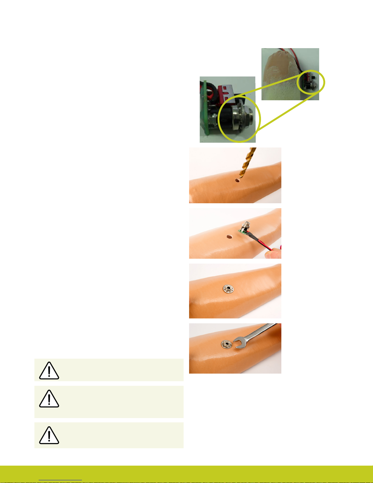
2.3 Charge Port Placement Assembly
It is important to provide sucient space for the charge port
between the inner and outer sockets. The charge port should be
positioned so that it is unaected by forces running through the
socket to prevent damage.
Create a drill hole of 8.0mm through the inner surface of the
prosthetic frame. Ensure a at surface has been created to
accommodate the charge port mounting frame (if installing a
switch block as an alternative to the charger port, create a drill
hole to cater for the panel mount).
Smooth the edges of the drill hole and insert the threaded
charge port. A minimum thread height of 3.2mm above the
socket surface is required for full engagement of washers and
locking nut.
Position the M8 Lock Washer and the M8 Flat Washer before
hand tightening the the locking nut.
Use a 3/8” wrench to tighten the locking nut. Do not overtighten.
Do not use pliers on the charge port.
Position the M8 Lock Washer and M8 Flat
Washer in place over the threaded shaft of the
charger port. Engage the M8 locking nut with
the threaded shaft and tighten rmly by hand.
The use of both the Lock Washer and Flat
Washer is vital to ensure the charge port is not
damaged by over tightening.
Part number: MA01140: Issue No. 1, April 2013

2.4 Battery Options
Two battery options are available for the i-limb ultra revolution, both of which have been specically designed to meet the power
requirements of the hand. Battery selection should be based on available space within the socket fabrication, shape of the residual limb
and the expected level of use. The corresponding DC socket and switch block will also be required.
i-limb 1,300 mAh Battery i-limb 2,000 mAh Battery
Capacity 1,300 mAh 2,000 mAh
Length
Battery Dimensions
Dummy Battery
Dimensions
Application Moderate Use Heavy Use
Part Number 000019
DC Socket SA000229 SA000234
Switch Block
Width 35mm (1.39”) 44mm (1.74”)
Height 6mm (0.24”) 7.5mm (0.30”)
Length 69mm (2.77”) 87mm (3.48”)
Width 35mm (1.39”) 45mm (1.80”)
Height
70mm (2.76”)
10mm (0.39”) Single cell
16mm (0.63”) Dual cell
SA000193 SA000192
80mm (3.17”)
11mm (0.44”) Single cell
19mm (0.76”) Dual cell
000231 Single cell
000232 Dual cell
Part number: MA01140: Issue No. 1, April 2013
10 of 57
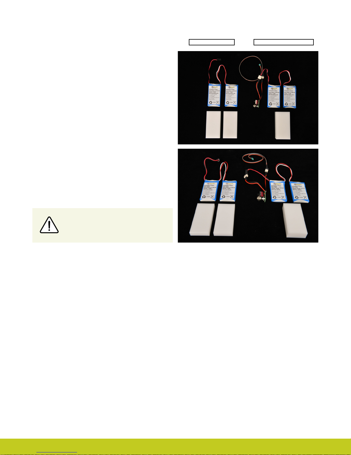
2.5 Battery Conguration
The images opposite show the 1,300 and 2,000mAh battery
options with battery dummy. The battery with DC connector and
battery with switch block connector are shown.
DC Connector Switch Block Connector
Only Touch Bionics batteries are approved
for use with the i-limb ultra revolution. Use of
alternative batteries will invalidate the warranty.
2.6 Battery Installation
The battery is designed to be mounted inside the socket interface,
ensure there is adequate space between the residual limb and
the wrist (or elbow) to accommodate the battery, charger port
and any other componentry. Use the battery dummy to fabricate
a relief for the battery in the socket interface.
When planning battery location and dummy placement for
fabrication, keep in mind a maximum distance of 135mm is
possible between cells due to wire length.
Easier access to the on/o switch may be possible by installing a
switch block; this allows the on/o switch to be positioned in a
more proximal position on the forearm. The use of a switch block
also provides an additional accessory switch for temporarily
disabling an electric wrist rotator or other electrical device, when
needed.
Part number: MA01140: Issue No. 1, April 2013
When the switch block is used in combination with a wrist rotator
the switch block will simultaneously turn o the i-limb ultra
revolution and the electronic wrist rotator.
Do not apply excessive force to the charger
socket interface during assembly.
A minimum of 2mm of free space should be provided surrounding
the charger port or switch block.
A at surface is needed to secure the charger port or switch block
to the socket interface frame. This may require additional shaping
of the frame section above the dummy battery. Use the Velcro
strip supplied to attach the battery to the inside of the socket
interface.
If the area between the residual limb and the lamination ring is
insucient to house the battery, you will need to position the
battery between the socket interface and the frame. This will be
necessary when:
• the residual limb is longer than 60% of the humeral or forearm
section of the prosthesis
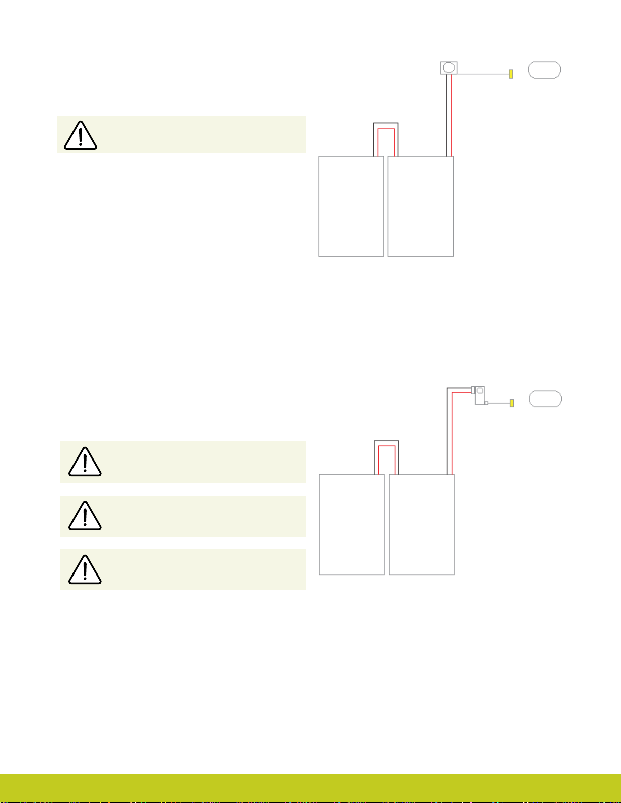
Wiring Schematic for 1300mAh Low Prole
Battery with D.C. Socket
®
2.5mm D.C. Socket
Co-axial Bush/Rotator
Low Prole Battery Cells Placed Side by Side
• the residual limb is a wrist or elbow disarticulation
• the battery is too large for the space available in the socket
interface frame
Cutting or modifying the battery wires in any
way will invalidate the warranty.
Do not bend or shape the battery in any way.
Ensure the battery is not subject to continued
pressure once tted.
SA000219
Switch Block Power Cable
Wiring Schematic for 1300mAh Low Prole
Battery with Switch Block
Co-axial Bush/Rotator
SA069031 Switch Block
SA069080 Switch Block with ying Leads
Low Prole Battery Cells Placed Side by Side
Part number: MA01140: Issue No. 1, April 2013
12 of 57

2.7 Battery Charging
Fully charge the battery prior to fabrication. This may take up to 2 hours.
The i-limb ultra revolution should only be charged using the Touch Bionics
charger supplied.
During charging turn the hand to the OFF position and remove the prosthesis
from the residual limb.
The light display is as follows:
For customers residing in parts of Europe and the United States, the charger
pictured to the right (g. 4) is used. The light display is either:
Red – rapid charge
Green – fully charged
Note: If a green light is noted when rst plugging in the device, ensure the
hand has been switched o.
On/O Switch
Charging time from full discharge is approximately:
1,300 mAh battery 90 minutes
2,000 mAh battery 180 minutes
For customers residing in the UK, Australia and South Africa the charger illustrated to the right (g. 5) is used. The light display is as follows:
Solid Amber – on standby
Slow ashing amber – pre-charge mode
Rapid ashing amber – Error
Slow ashing green – maintenance charge
Rapid ashing green – rapid charge
Solid green – fully charged
Charging time from full discharge is approximately:
1,300 mAh battery 180 minutes
2,000 mAh battery 180 minutes
Insert the charger lead connector into the charge port. A “click” should be
heard on connection.
Insert the charger into the power outlet.
To remove the charger lead connector, grip the connector and pull directly
away from the port. Consult warnings and precautions in section 7.3.
DO NOT PULL THE CABLE TO REMOVE THE LEAD.
Figure. 4
Figure. 5
To ensure the i-limb ultra revolution is continually functional,
charge at the end of each day.
Switch the hand OFF to preserve battery power
when not in use.
Only use supplied Touch Bionics charger to charge battery.
Replace the battery annually for optimal performance.
Part number: MA01140: Issue No. 1, April 2013
3.0 Wrist
3.1 Wrist Connection Options
The following wrist connection options are available for the i-limb
ultra revolution:
1
Quick Wrist Disconnect (QWD)
2
Wrist Disarticulation
The following exible wrist options are available for the i-limb
ultra revolution:
1
Flex Wrist
2
Multi-ex Wrist
See section 3.4 and 3.5 respectively for FlexWrist and Multi-ex
Wrist tting information.
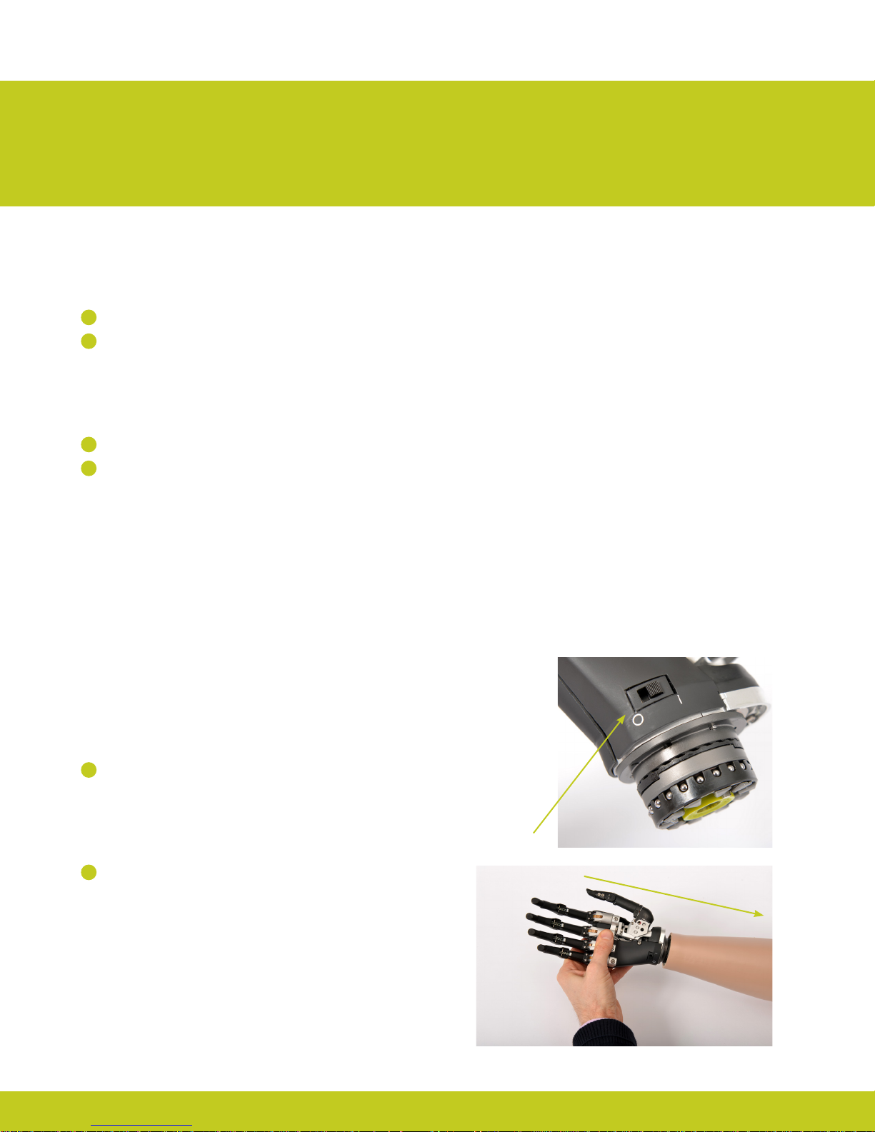
3.2 Quick Wrist Disconnect (QWD)
The QWD is supplied by Touch Bionics. Disconnection of the i-limb
ultra revolution tted with a QWD from the socket is completed
as follows:
Connecting the i-limb ultra revolution using the
QWD
1
Ensure the i-limb ultra revolution is switched o.
2
Align the QWD connection of the i-limb ultra revolution with
the connection in the forarm socket.
On/O Switch
Part number: MA01140: Issue No. 1, April 2013
14 of 57
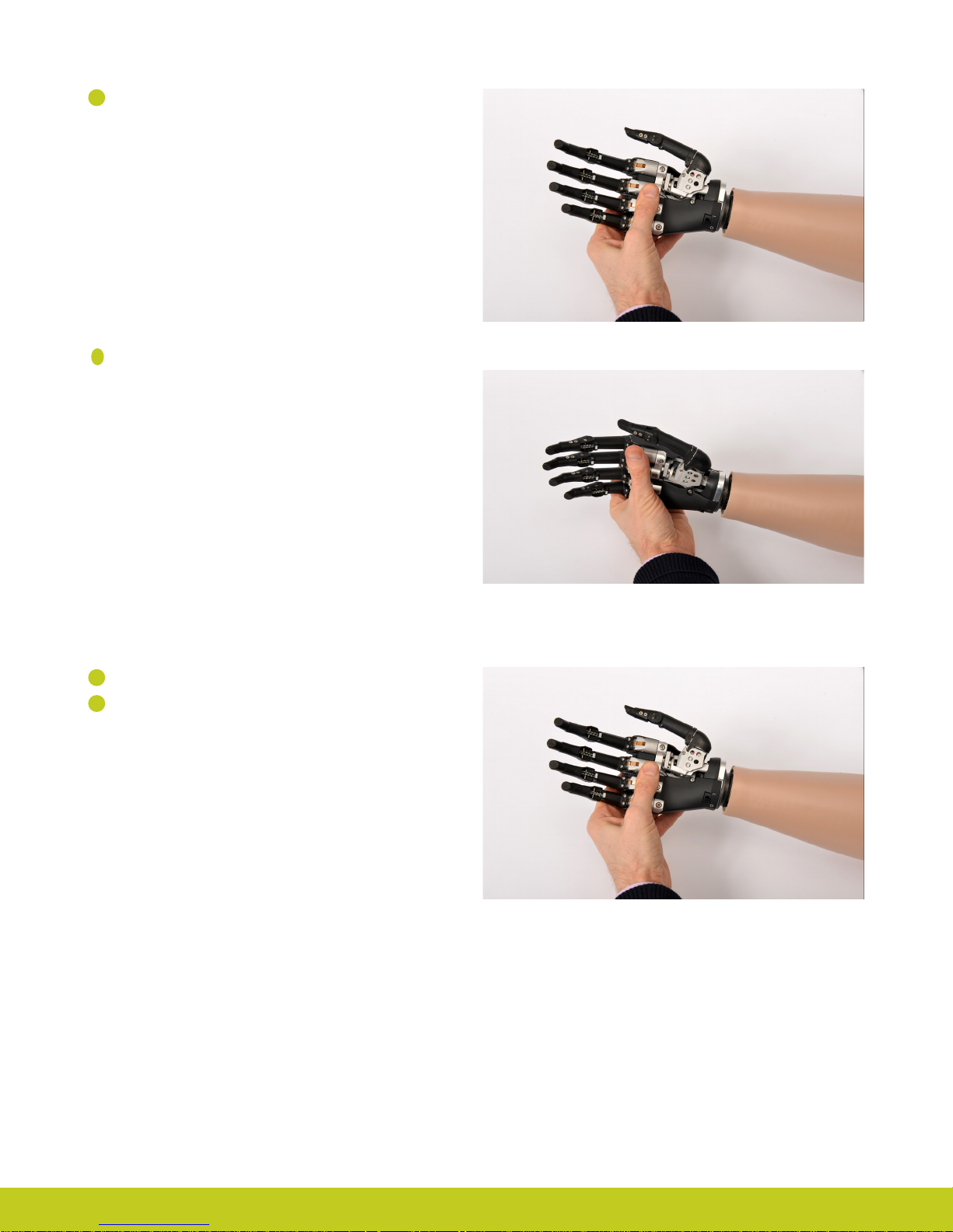
3
Engage the coupling.
4
Test the connection is fully engaged with a slight rotation.
Disconnecting the i-limb ultra revolution using
the QWD
1
Ensure the i-limb ultra revolution is switched o.
2
Support the i-limb ultra revolution in the palm of the hand.
Part number: MA01140: Issue No. 1, April 2013

2
3
Rotate the i-limb ultra revolution through 360° in either
direction until a click is heard
3
4
The i-limb ultra revolution will now disengage from the
socket. Support the hand and withdraw away from the
socket
3.3 Wrist Disarticulation
The wrist disarticulation is fabricated directly into the socket
frame and then attached to the i-limb ultra revolution by the
following steps:
1
Disconnect the Palm Fairing from the i-limb ultra revolution
chassis by unscrewing the screw in the palmar surface using a
T10 Screwdriver (supplied).
Part number: MA01140: Issue No. 1, April 2013
16 of 57
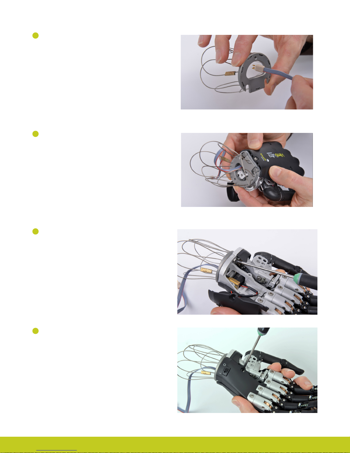
2
Remove the Wrist Disarticulation and feed the power cable
through.
3
Align the slots and slide the Wrist Disarticulation plate onto
the WD Lamination Plate at base of the i-limb ultra revolution
ensuring it is rmly engaged.
4
Secure the Wrist Disarticulation to the WD Lamination Plate
using the T10 screw and T10 Screwdriver supplied.
5
Replace the Palm Fairing onto the chassis by hand tightening
the screw in the palmar surface using the T10 Screwdriver
supplied. Ensure that the Palm Fairing does not pinch the
wiring.
Part number: MA01140: Issue No. 1, April 2013

6
Fabrication of the Wrist Disarticulation into the socket
must allow for disengagement of the hand from the Wrist
Disarticulation plate. Otherwise complete fabrication of the
Wrist Disarticulation into the socket in the usual manner.
To disconnect the Wrist Disarticulation from the i-limb ultra
revolution complete the above steps in reverse:
1
Disconnect the Palm Fairing from the Chassis. Be careful to
not damage wiring when removing the Palm Fairing.
2
Loosen the WD Lamination Plate Screw from the Wrist
Disarticulation plate.
3
Slide the Wrist Disarticulation o the base of the i-limb ultra
revolution.
4
Separate the i-limb ultra revolution from the Wrist
Disarticulation, drawing the Basket cable through the Wrist
Disarticulation.
For guidance on fabrication consult section 2.2 Socket Fabrication.
3.4 Flex Wrist
The Flex Wrist is connected directly to a QWD and oers three
wrist positions, 30° dorsiexion, 0° neutral and 30° palmar exion.
The control switch is positioned on the palmar surface of the wrist
and is manually operated. (See i-limb ultra revolution ex data
sheet for more information on the Touch Bionics website: www.
touchbionics.com/downloads/document-library/).
Control
Switch
Part number: MA01140: Issue No. 1, April 2013
18 of 57
 Loading...