

Toto ZL Series, TLP02301U, TLP02304U, TLP02307U Installation And Owner's Manual
Warranty Registration and Inquiry
For product warranty registration, TOTO U.S.A. Inc. recommends online warranty registration. Please visit
our web site http://www.totousa.com. If you have questions regarding warranty policy or coverage, please contact TOTO U.S.A. Inc., Customer Service Department, 1155 Southern Road, Morrow, GA 30260
(888) 295-8134 or (678) 466-1300 when calling from outside of U.S.A.
Installation and Owner’s Manual
Manual de instalación y del propietario
Manuel d’installation et d’utilisation
Manual de Instalação e do Proprietário
Single Handle Lavatory Faucet
Grifo de Lavabo de Una Manija
Robinet de Lavabo à une Manette
Faucet de Alça Única com Balcão de Banheiro
ZL
TLP02301U
TLP02304U
TLP02307U
2
ENGLISH
Installation Procedure.....................4
Care and Cleaning..........................8
Maintenance....................................9
Warranty..........................................12
Rough-In Dimensions.....................46
Thanks for Choosing TOTO!..........2
Warnings..........................................2
Before Installation...........................2
Included Parts..................................3
Tools You Will Need........................3
Specifications...................................3
TABLE OF CONTENTS
THANK YOU FOR CHOOSING TOTO!
The mission of TOTO is to provide the world with healthy, hygienic and more
comfortable lifestyles. We design every product with the balance of form and
function as a guiding principle. Congratulations on your choice.
WARNINGS
BEFORE INSTALLATION
For safe operation of the faucet, please observe the following:
Operating Pressure:
Minimum Pressure....................20 psi (138 kPa), dynamic
Maximum Pressure...................80 psi (551 kPa), static
Do not use the product at an ambient temperature below 32º F (0º C)
Observe all local plumbing codes.
Before installing the faucet, be sure to thoroughly flush the supply pipes of dirt
and debris.
Make sure the water supply is shut off at the stop valve.
Read these instructions carefully to ensure proper installation.
TOTO reserves the right to update product design without notice.
3
ENGLISH
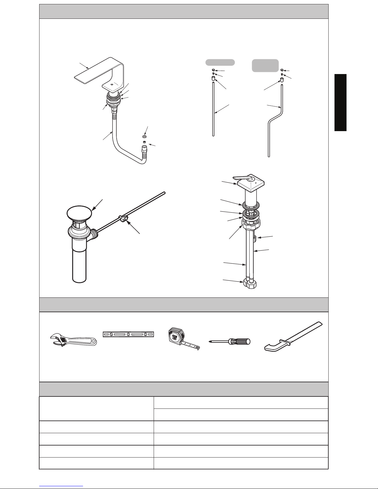
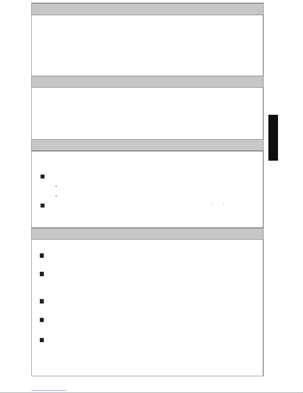
Check to make sure you have the following parts indicated below:
INCLUDED PARTS
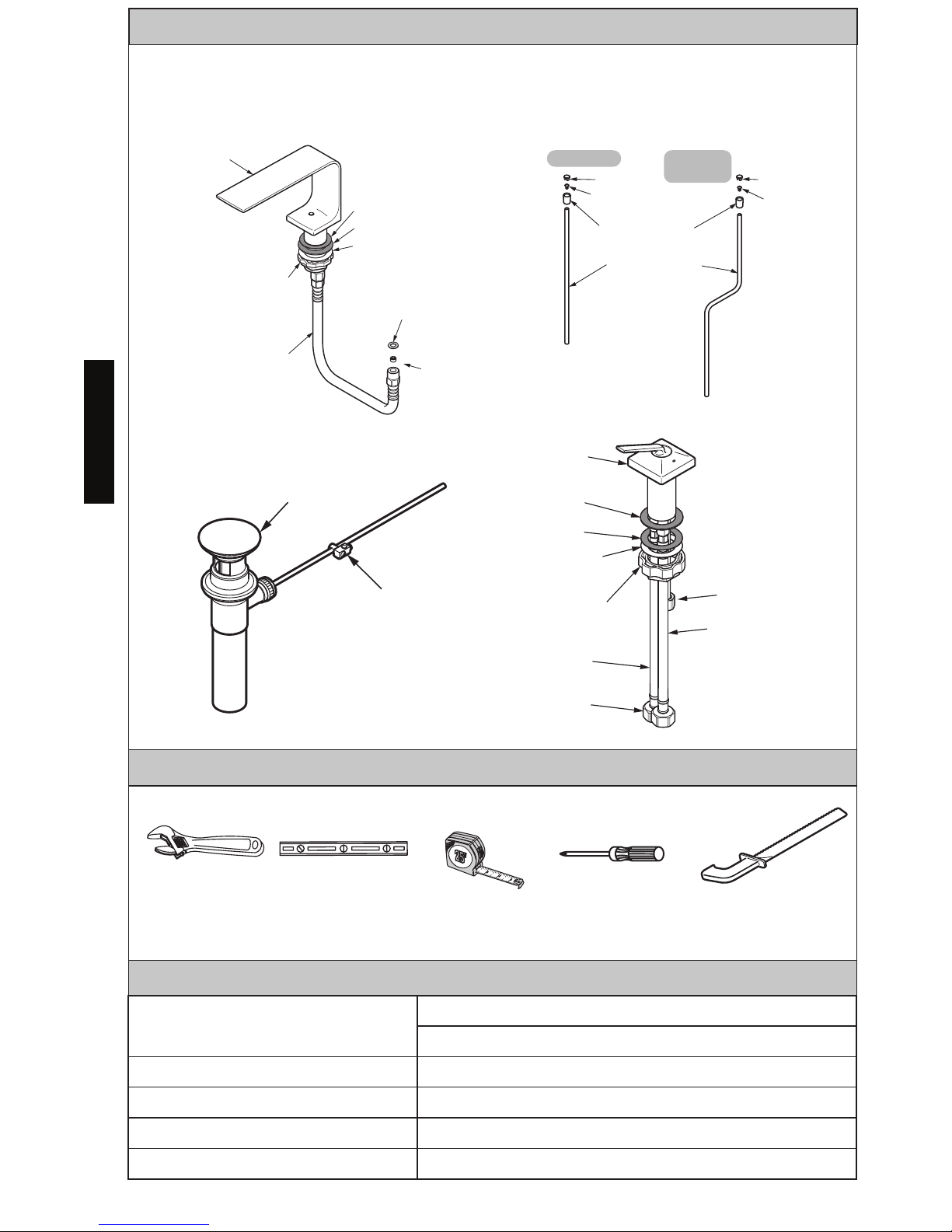
TOOLS YOU WILL NEED
Level
Tape
Measure
SPECIFICATIONS
Water Supply Pressure
Minimum required: 20 psi (138 kPa) (Flowing)
Maximum allowed: 80 psi (551 kPa)
Water Supply Connection
3/8 Comp
Ambient Temperature 32~104°F (0~40°C)
Humidity Max. 90% RH
Flow Rate Maximum 1.2 gallon/min (4.5 L/min)
Adjustable
Wrench
.
Spout Assembly
Spout
Gasket
Gasket
Gasket
Flow
regulator
Slip Washer
Mounting nut
(without
groove)
Mixed
supply
hose
TLP02301
TLP02304
TLP02307
Drain lift rod
Lid Lid
Screw
Screw
Pushbutton
Drain lift rod
Handle assembly
Handle
assembly
Gasket
Gasket
Slip
Washer
Mounting nut
(with groove)
Hot water
supply hose
Cold water
supply hose
Drain assembly
Drain assembly
Drain lift rod
connecting part
Nut
9/16-24 UNEF
Phillips
Screwdriver
Hacksaw
4
ENGLISH
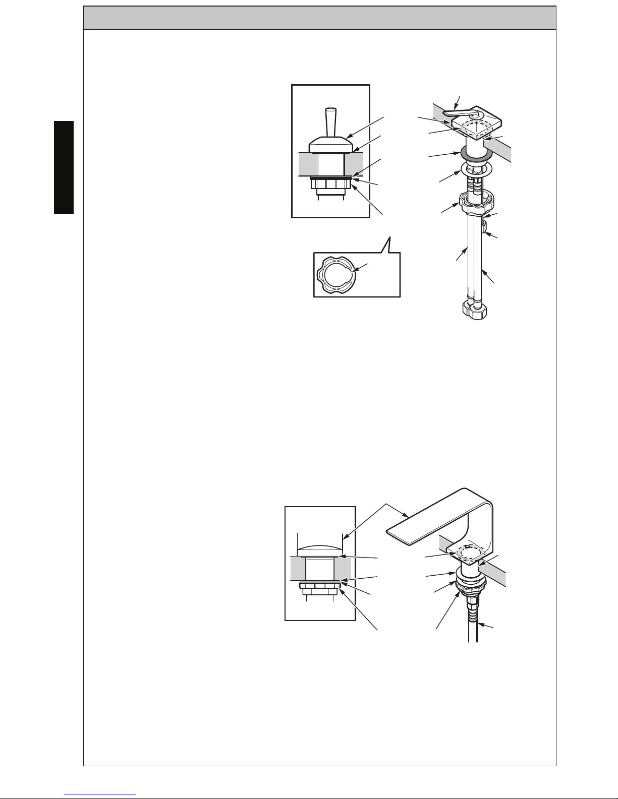
INSTALLATION PROCEDURE
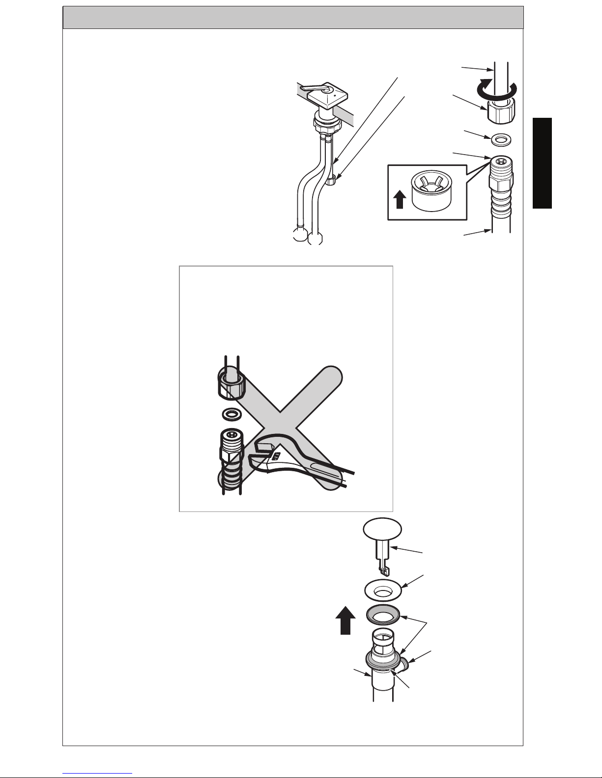
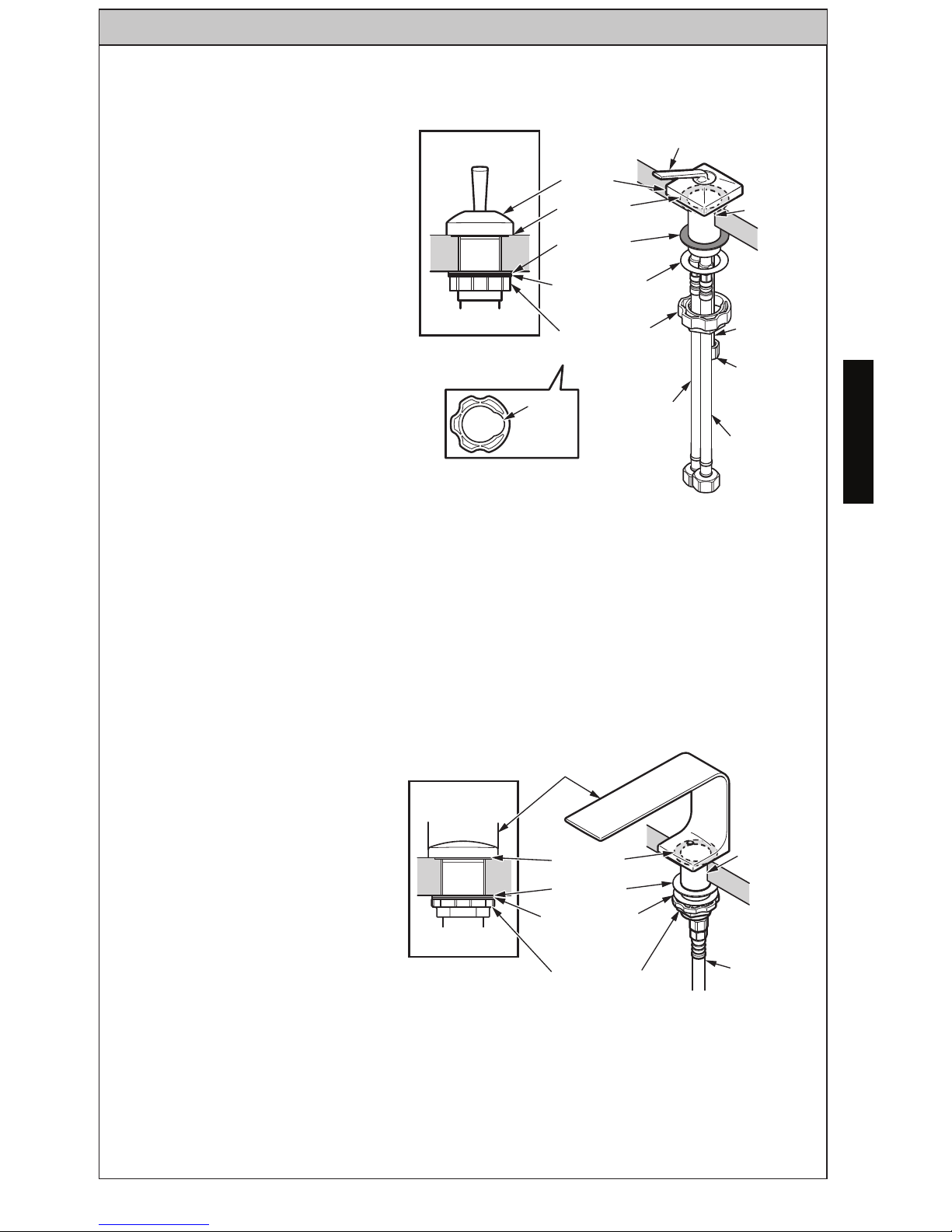
1. Mount the handle
assembly.
(1) Insert the HOT/COLD
water supply hoses into the
mounting hole.
(2) Pass the HOT/COLD
water supply hoses through
the gasket, the slip washer
and the mounting nut
(with groove) one by one.
Then, pass the nut of the
connecting pipe through
the groove and secure the
handle assembly. (ill. 1)
2. Mounting the spout
assembly.
(1) Set the gasket, the slip
washer and the mounting nut
(without groove) on the spout
and secure the spout. (ill.2)
IMPORTANT: Align the spout so that it comes out the center of the
mounting hole.
ill. 1
Section View
Handle
assembly
Lever
handle
Mounting
hole
Connecting
pipe
Gasket
Gasket
Slip
Washer
Mounting
nut
(with groove)
Hot water
supply hose
Groove
Cold water
supply hose
ill. 2
Section View
Spout
Gasket
Gasket
Slip washer
Mounting nut
Mixed supply
hose
Mounting
hole
IMPORTANT: Align the shaft
position so that the handle
assembly comes to the center
of the mounting hole.
(3) Connect the hoses to the supply lines. The left hose (marked with red
band) connects to the hot water supply. The right hose connects to the
cold water supply. Thighten with wrench as needed.
5
ENGLISH
INSTALLATION PROCEDURE
ill. 3
Handle Assembly
Connecting
pipe
Nut
Gasket
(black)
Flow regulator
Up
Mixed supply hose
3. Connection of the
mixed supply hose.
(1) Turn the nut of the
connecting pipe and
connect the mixed supply
hose. (ill. 3)
Never turn the nut on the
mixed supply hose side.
The hose may twist and
cause water to leak.
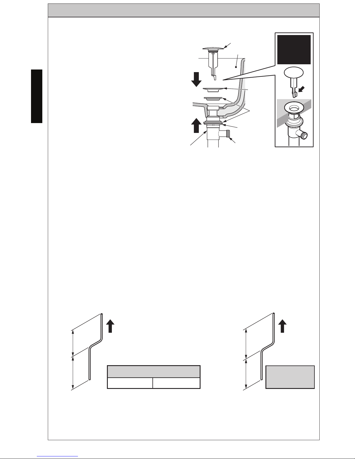
4. Install drain assembly.
(1) Remove the plunger,
flange and gasket from
the drain assembly by
unfastening the flange and
pulling these parts from
the drain. (ill. 4)
ill. 4
Plunger
Flange
Deformed
gasket
Kick lever
box
Flanged nut
Drain
assembly
6
ENGLISH
INSTALLATION PROCEDURE
(113)
(145)
(113)
(145)
(2) Insert the drain body up
through the drain hole from
below the lavatory. If necessary,
turn the nut and push the washer
and gasket (thick) down to allow
for clearance.
While holding the drain body in
place, fasten the flange to the
drain body from the top. Ensure
that the gasket is between the
flange and the lavatory as shown.
Once the flange is fully seated,
turn the nut below the lavatory
up until a good seal is formed.
(3) Mount the drain lift rod in the proper direction. (ill. 6)
ill. 5
Lavatory
Plunger
Flange
Deformed
gasket
Flanged nut
Lever hole
Drain
assembly
Attention
to direction
of plunger
Spout
Part number of the lavatory
LT475 LT476
Spout
Unit: inch
(mm)
Other than the
part numbers
written on the left
Short
4-7/16”
Short 4-7/16”
Long
5-11/16”
Long 5-11/16”
ill. 6
Do not overtighten!
(ill. 5)
Reinsert the plunger if needed.
7
ENGLISH
INSTALLATION PROCEDURE
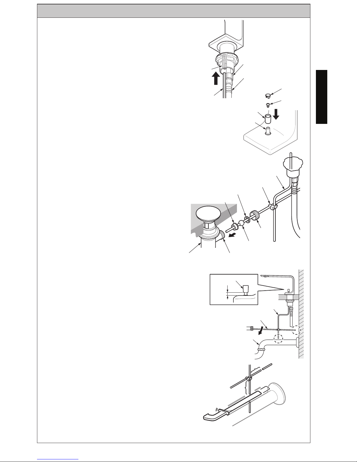
(4) Install drain assembly (continued)
(a) Insert the drain lift rod into the
guide from below the spout body.
(b) Mount the pushbutton, screw and
lid on the drain lift rod in that order.
(ill. 7)
5. Connect the drain assembly.
(1) Adjust the position of the drain lift rod so
that the clearance between the spout and the
pushbutton is 3/16”- 3/8” (5~10mm).
(2) Lower the pivot arm to the lowest position
in the condition described in part (a), secure
the screw of the drain lift rod connecting part
to anchor the pivot arm and the drain lift rod.
(ill. 9)
(c) Fit bushing B, the pivot ball nut and the drain
lift rod connecting part on the pivot arm and fit
bushing A on the drain assembly.
(d) After passing the drain lift rod
through the drain lift rod connecting
part, pass the pivot arm through
the hole of the plunger of the
lever hole and secure it with
the pivot ball nut. (ill. 8)
*
*
CAUTION
If the pivot arm and the drain lift rod interfere with
the wall and the water drain pipe, cut them to a
length that they do not interfere. (ill. 10)
Make sure water is flowing properly after installing
the faucet.
ill. 10
ill. 7
Guide
Drain lift rod
Connecting pipe
Mixed supply hose
Lid
Screw
Pushbutton
Drain lift rod
ill. 8
.
Drain lift rod
Drain lift rod
connecting part
Bushing B
Bushing A
Drain assembly Lever hole
Pivot arm
Pivot Ball
Nut
*Cut 3/8”- 13/16”(10~20) from
the anchoring metal fittings.
ill. 9
Water drain pipe
Pivot arm
Drain lift rod
Pushbutton
Wall
3/16”~ 3/8”
(5~10)
8
ENGLISH
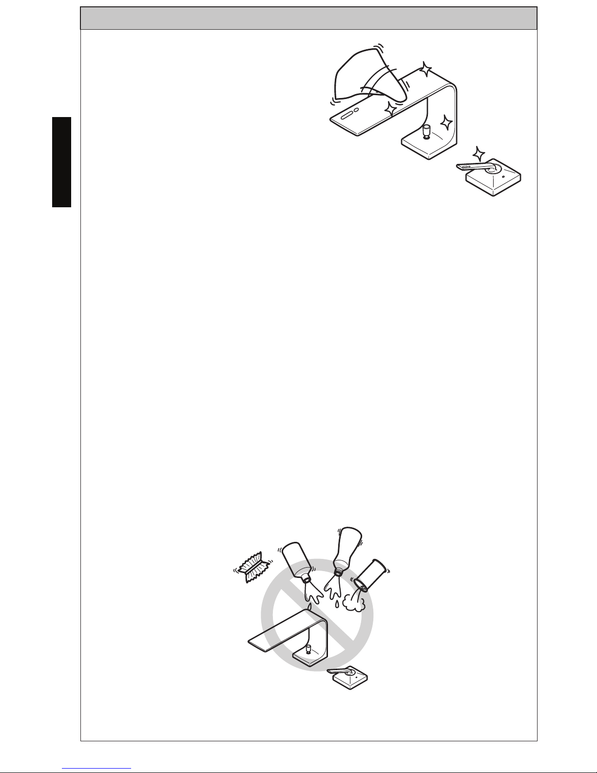
Clean the parts regularly to prevent the
accumulation of dirt and lime-scale.
For daily cleaning, use a neutral cleaner.
Acids are necessary ingredients of
cleaning materials for removing lime.
However, please pay attention to the
following points when cleaning fittings
(ill. 11):
Only use cleaning materials which
are explicitly recommended for this type of application.
Never use cleaning materials which contain hydrochloric, formic or
acetic acid, as they may cause considerable damage.
Do not use phosphoric acid as it can also cause damage.
Never use cleaning materials or appliances with an abrasive effect,
such as cleaning powders, sponges or microfiber cloths.
Please follow the cleaning material manufacturer’s instructions.
When using spray cleaners, spray first onto a soft cloth or sponge.
Never spray directly onto the fittings, as drops could enter openings
and gaps, which can then cause damage.
After cleaning, rinse thoroughly with clean water to remove any
cleaner residue.
Components with damaged surfaces must be exchanged, otherwise
this can cause an injury. Damage caused by improper treatment will
not be covered by our warranty.
CARE AND CLEANING
ill. 11
Thinner
Acidic/alkali detergents
Cleansers
9
ENGLISH
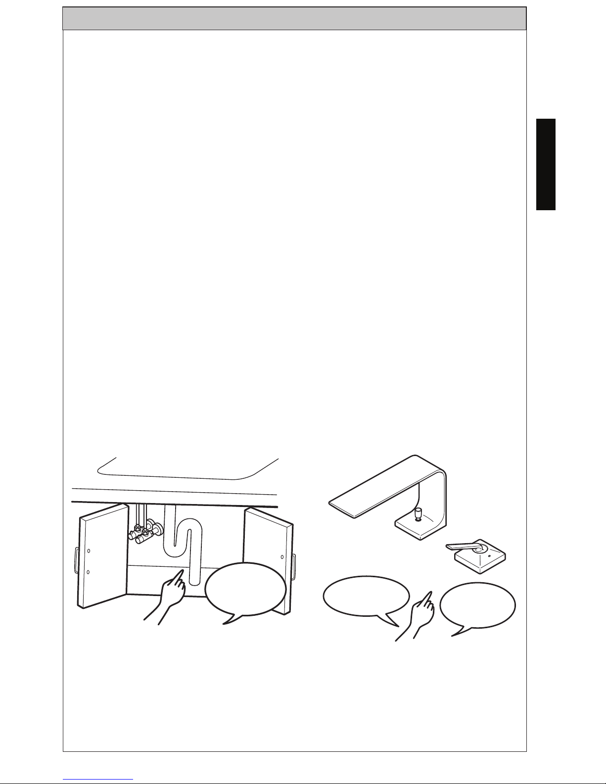
Check your faucet at least once a month for the following potential
problems and to do the following maintenance procedures:
Inspect for Leakage
• Check all water connections for signs of leakage. (ill. 12)
Looseness of the product
• Check for any parts that seem abnormal such as being loose as
compared when you first began using the product. (ill. 13)
Tighten the Spout and Handle Assembly
• If the spout or handle is loose, tighten the mounting nut underneath
the spout or handle assembly.
If you continue to use the product with loose piping, weight is applied to
the pipe(s) and may result in water leakage.
If you leave any abnormality like looseness unfixed, part(s) may break or
plated surfaces may crack whereby injuring you.
If you find a loose part, remove the cap and retighten the screw that secures the main body. In case the looseness cannot be repaired, ask your
dealer or seller for repairs (subject to billing).
MAINTENANCE
No
abnormality
No
looseness
ill. 13
ill. 12
No Water
Leaks!
10
ENGLISH
To clean the nozzle screen:
1. Loosen and remove the set screw using a hexagonal wrench (2 mm).
(ill. 16)
2. Insert the flat-blade precision screwdriver in the notch between the
nozzle screen case and the spout, and remove the nozzle screen case.
Pay attention not to lose the O-ring of the nozzle screen case.
MAINTENANCE
(M3x7)
Flat-blade
precision
screwdriver
Spout
O-ring
(Semitransparent)
Nozzle screen
case
Set screw
Notch
Hexagonal wrench
(2mm)
A
B
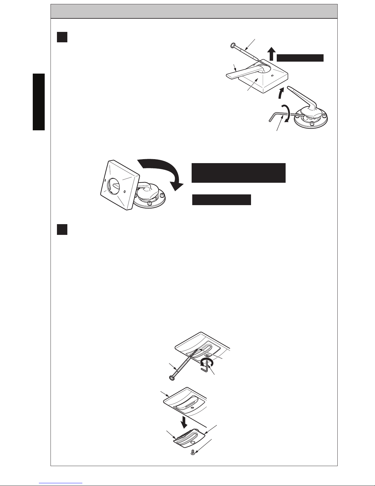
How to secure the lever handle.
Close the stop valve before starting work.
1. Insert a flat-blade precision screwdriver
into the clearance between the lever handle
and the cover, and lift and remove the cover.
(ill. 14)
2. Lift the lever handle and retighten the
setscrew with a hexagonal wrench (2.5mm)
3. Pass the cover over the lever handle,
press it into the counter surface and mount
it. (ill. 15)
Pay attention to the
direction of the cover.
Mount cover.
ill. 14
Flat-blade precision
screwdriver
Lever
Handle
Remove Cover
Cover
Hexagonal wrench
(2.5mm)
ill. 15
ill. 16
11
ENGLISH
MAINTENANCE
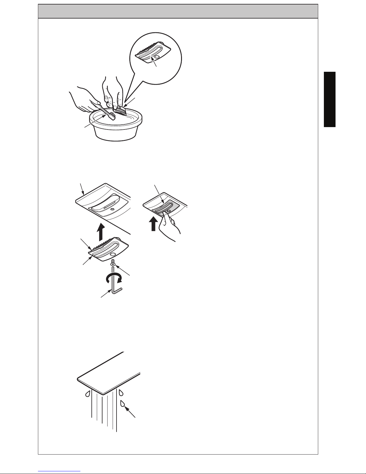
3. Remove dirt and debris
caught in the nozzle screen using
a toothbrush, etc. (ill. 17)
4. Assemble the nozzle screen
case on the spout and lock it in
place with the set screw.
Press the nozzle screen case
into the spout with a finger and
tighten the setscrew. (ill. 18)
5. When mounting work is complete, check the nozzle screen
for any water leaks. If the nozzle
screen case is not mounted properly, re-mount it. (ill. 19)
ill. 19
Leak
ill. 17
Nozzle
screen
Nozzle Screen-
Case
Toothbrush
(M3x7)
)
ill. 18
Nozzle Screen
Case
Press it IN
with a finger
O-Ring
(Semi
Transparent)
Nozzle Screen
Case
Hexagonal wrench
(2mm)
Set screw
Spout
12
ENGLISH
WARRANTY
1. TOTO ers (“Product”) to be free from defects in
materials and workmanship during normal use when properly installed and serviced, for a period of three (3) years
from date of purchase. This limited warranty is extended only to the ORIGINAL PURCHASER of the Product and is
not transferable to any third party, including but not limited to any subsequent purchaser or owner of the Product.
This warranty applies only to TOTO Product purchased and installed in North, Central and South America.
2. TOTO’s obligations under this warranty are limited to repair, replacement or other appropriate adjustment, at
TOTO’s option, of the Product or parts found to be defective in normal use, provided that such Product was properly
sa snoitcepsni hcus ekam ot thgir eht sevreser OTOT .snoitcurtsni htiw ecnadrocca ni decivres dna desu ,dellatsni
ni strap ro robal rof egrahc ton lliw OTOT .tcefed eht fo esuac eht enimreted ot redro ni yrassecen eb yam
connection with warranty repairs or replacements. TOTO is not responsible for the cost of removal, return and/or
reinstallation of the Product.
5. THIS WARRANTY GIVES YOU SPECIFIC LEGAL RIGHTS. YOU MAY HAVE OTHER RIGHTS WHICH VARY
FROM STATE TO STATE, PROVINCE TO PROVINCE OR COUNTRY TO COUNTRY.
6. To obtain warranty repair service under this warranty, you must take the Product or deliver it prepaid to a TOTO
service facility together with proof of purchase (original sales receipt) and a letter stating the problem, or contact
a TOTO distributor or products service contractor, or write directly to TOTO U.S.A., INC., 1155 Southern Road,
Morrow, GA 30260 (888) 295 8134 or (678) 466-1300, if outside the U.S.A. If, because of the size of the Product
or nature of the defect, the Product cannot be returned to TOTO, receipt by TOTO of written notice of the defect
esoohc yam OTOT ,esac hcus nI .yreviled etutitsnoc llahs )tpiecer selas lanigiro( esahcrup fo foorp htiw rehtegot
to repair the Product at the purchaser’s location or pay to transport the Product to a service facility.
THIS WRITTEN WARRANTY IS THE ONLY WARRANTY MADE BY TOTO. REPAIR, REPLACEMENT OR OTHER APPROPRIATE
ADJUSTMENT AS PROVIDED UNDER THIS WARRANTY SHALL BE THE EXCLUSIVE REMEDY AVAILABLE TO THE ORIGINAL
PURCHASER. TOTO SHALL NOT BE RESPONSIBLE FOR LOSS OF THE PRODUCT OR FOR OTHER INCIDENTAL, SPECIAL
OR CONSEQUENTIAL DAMAGES OR EXPENSES INCURRED BY THE ORIGINAL PURCHASER, OR FOR LABOR OR OTHER
COSTS DUE TO INSTALLATION OR REMOVAL, OR COSTS OF REPAIRS BY OTHERS, OR FOR ANY OTHER EXPENSE NOT
SPECIFICALLY STATED ABOVE. IN NO EVENT WILL TOTO’S RESPONSIBILITY EXCEED THE PURCHASE PRICE OF THE
PRODUCT. EXCEPT TO THE EXTENT PROHIBITED BY APPLICABLE LAW, ANY IMPLIED WARRANTIES, INCLUDING THAT
OF MERCHANTABILITY OR FITNESS FOR USE OR FOR A PARTICULAR PURPOSE, ARE EXPRESSLY DISCLAIMED. SOME
STATES DO NOT ALLOW LIMITATIONS ON HOW LONG AN IMPLIED WARRANTY LASTS, OR THE EXCLUSION OR
LIMITATION OF INCIDENTAL OR CONSEQUENTIAL DAMAGES, SO THE ABOVE LIMITATION AND EXCLUSION MAY NOT
APPLY TO YOU.
3. This warranty does not apply to the following items:
b. Damage or loss resulting from any accident, unreasonable use, misuse, abuse, negligence, or improper
care, cleaning, or maintenance of the Product.
c. Damage or loss resulting from sediments or foreign matter contained in a liquid soap system.
ro/dna hsrah a ni tcudorP eht fo noitallatsni morf ro noitallatsni reporpmi morf gnitluser ssol ro egamaD .d
tion of the Product.
e. Damage or loss resulting from electrical surges or lightning strikes or other acts which are not the fault of
f. Damage or loss resulting from normal and customary wear and tear, such as gloss reduction, scratching or
fading over time due to use, cleaning practices or water or atmospheric conditions, including but not limited
to, the use of bleach, alkali, acid cleaners, dry (powder) cleaners or any other abrasive cleaners or the use
of metal or nylon scrubbers.
4. In order for this limited warranty to be valid, proof of purchase is required. TOTO encourages warranty registration
upon purchase to create a record of Product ownership at http://www.totousa.com is required. TOTO encourages
registration upon purchase and failure to register will not diminish you r limited warranty rights.
13
ESPAÑOL
Procedimiento de Instalación.......15
Cuidado y Limpieza.......................19
Mantenimiento...............................20
Garantía..........................................23
Bosquejo........................................46
¡Gracias por elegir TOTO!.........13
Advertencias................................13
Antes de la Instalación................13
Partes Incluidas............................14
Herramientas que necesitarás....14
Especificaciones...........................14
TABLA DE CONTENIDO
¡GRACIAS POR ELEGIR TOTO!
La misión de TOTO es proporcionar al mundo estilos de vida saludables,
higiénicos y más cómodos. Diseñamos cada producto con el equilibrio de
forma y función como principio rector. Felicidades por tu elección.
ADVERTENCIAS
ANTES DE LA INSTALACIÓN
Para un funcionamiento seguro del grifo, tenga en cuenta lo siguiente:
Presión operacional:
Presión mínima .................... 20 psi (138 k Pa), dinámica
Presión máxima ................... 80 psi (551 kPa), estático
No use el producto a una temperatura ambiente inferior a 32º F (0º C)
Observe todos los códigos de plomería locales.
Antes de instalar el grifo, asegúrese de enjuagar a fondo los tubos de
suministro de suciedad y residuos.
Asegúrese de que el suministro de agua esté cerrado en la válvula de cierre.
Lea estas instrucciones cuidadosamente para asegurar una instalación correcta.
TOTO se reserva el derecho de actualizar el diseño del producto sin previo
aviso.
14
ESPAÑOL
Asegurese de que tiene las partes indicadas a continuación:
PARTES INCLUIDAS
HERRAMIENTAS QUE NECESITARÁS
Nivel
Cinta Metrica
ESPECIFICACIÓNES
Presión de suministro de agua
Mínimo requerido: 20 psi (138 kPa) (corriente)
Máximo permitido: 80 psi (551 kPa)
Conexión de suministro de agua
3/8 Comp
Temperatura ambiente 32~104°F (0~40°C)
Humedad Max. 90% RH
Flujo Máximo de 1,2 galón/min (4,5 L/min)
Llave
Ajustable
.
Ensamblaje de salida para tina
Salida para tina
Junta
Junta
Junta
Regulador
de flujo
Arandela de
deslice
Tuerca de
montaje
(sin perforación)
Manguera
de suministro
mixto
TLP02301
TLP02304
TLP02307
Vara de Desagüe
Tapa
Tapa
Tornillo
Tornillo
Botón
Vara de Desagüe
Ensamblaje de Manija
Ensamblaje de
manija
Junta
Junta
Arandela de
deslice
Tuerca de montaje
(con perforación)
Manguera de
suministro de
agua caliente
Manguera de
suministro de
agua fria
Ensamblaje de desagüe
Ensamblaje de desagüe
Parte conectora de la
vara de desagüe
Tuerca
9/16-24UNEF
Destornillador
Phillips
Sierra
15
ESPAÑOL
PROCEDIMIENTO DE INSTALACIÓN
1. Monte el ensamblaje de la
manija.
(1) Inserte las mangueras de
suministro de agua CALIENTE/
FRÍA en el orificio de montaje.
(2) Pase las mangueras de
suministro de agua CALIENTE/
FRÍA a través de la junta, la
arandela de deslice y la tuerca
de montaje (con perforación)
una a una. Luego, pase la
tuerca de la tubería conectora
a través de la perforación y
asegure el ensamblaje de la
manija. (ill. 1)
2. Montar el ensamblaje de
la salida para tina.
(1) Coloque la junta, la
arandela de deslice y la
tuerca de montaje (sin
perforación) en la salida para
tina y asegúrela. (ill.2)
IMPORTANTE:
Alinee la salida para tina de manera que salga del centro del orificio
de montaje.
ill. 1
Vista de
Sección
Ensamblaje
de Manija
Palanca
Orificio de
montaje
Tubo de
connección
Tuerca
Junta
Junta
Arandela de
deslice
Tuerca de montaje
(con perforación)
Manguera de
suministro de
agua caliente
Perforación
Manguera de
suministro de
agua fría
ill. 2
Salida para tina
Junta
Junta
IMPORTANTE: Alinee la posición del eje de manera que el ensamblaje de
la manija llegue al centro del orificio de montaje.
(3) Conecte las mangueras a las líneas de suministro. La manguera
izquierda (marcada con una banda roja) conecta el suministro de agua
caliente. La manguera derecha conecta el suministro de agua fría. Ajuste
con la llave lo necesario.
Vista de
Sección
Orificio de
montaje
Manguera
de suministro
mixto
Tuerca de montaje
Arandela de
deslice
 Loading...