

Page 1
0GU3036
®
Installation and Owner’s Manual
Thermostatic Mixing Valve Trim
TS170T
English
Important Safeguards----------------1
Specifications --------------------------2
Before Installation --------------------2
Set-up Drawing-------------------------3
Components ----------------------------3
Installation Procedure ----------4~6
Check the product---------------------7
Before use----------------------------7~8
Maintenance-----------------------------9
Troubleshooting -----------------------9
Set-up Options -----------------------10
Replacement Parts-------------------10
Warranty---------------------------------11
RENESSE
Español
Contents
™
2007.5
Français
Thank you for your recent purchase
•
of the TOTO product . Please read
the enclosed information to ensure
the safe use of your product
.
Page 2
Important Safeguards
(For your safety please follow the instructions below)
Read the “Important Safeguards” section thoroughly before installing the product.
●The following symbols indicate safe and proper use of the
product. Failure to observe them may result in injury or property
damage. The symbols and their meanings are as follows.
●The following table demonstrates the use
of safety symbols in this manual.
Do Not
ENGLISH
Do not
disassemble
Mandatory
Warning
Caution
Failure to observe this symbol may
result in serious injury.
Failure to observe this symbol may
result in injurty or property damage.
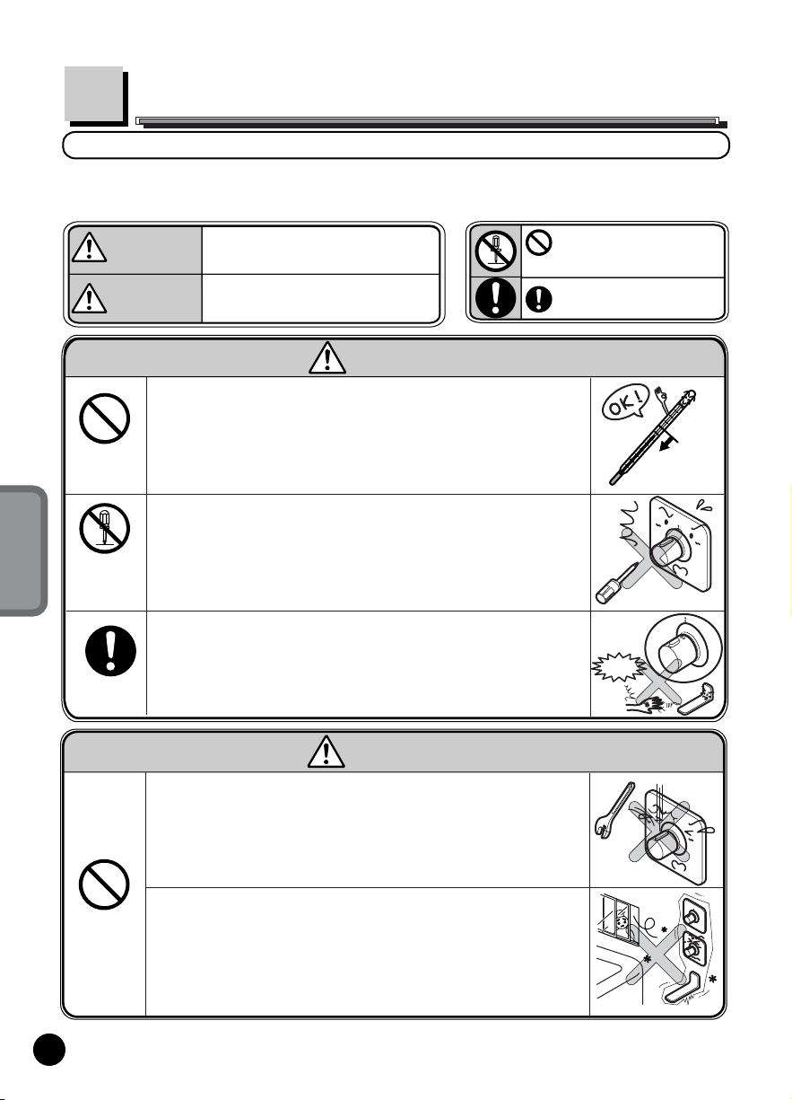
Warning
Do not use hot water supply that is higher than 185°F
(85°C). Do not use steam as hot water supply.
If water is hotter than 185°F is used. If it is broken, property damage,
scalding, and other injuries may occur.
Do not disassemble or modify the item in any way not
described in this manual
If the system is broken, property damage, scalding and other injuries
are likely to occur.
The valve should be calibrated by the installer so that water
temperature will be fixed 104˚F (40˚C) at the mark.
Scalding may occur if the temperature is not checked and valve is
not calibrated as necessary.
Caution
Absolutely Do NOT.
Do not disassemble
Mandatory!
Less
than185°F
(85° C)
HOT
Ah!
1
Do Not
Do not strike or kick the product.
If the system is broken, property damage, scalding, and other injuries
may occur.
Do not use the product at temperature exceeding what local
codes allow.
If parts are damaged, property damage, scalding and other injuries may
occur.
Freezing
Page 3
Specification
Water Supply
Pressure
Minimum pressure
Maximum pressure
Supplied Water Temperature
Water Quality
Ambient Temperature
Water Supply Connection
Humidity
Depending on the model, some specifications may differ.
20 psi (0.15MPa)(flowing pressure)
125 psi (0.75MPa)(static)
Less than 185˚F (85˚C)
Water that meet National/Primary drinking water
regulation
34 - 104˚F (2~40˚C)
1/2” NPT
Maximum 90% RH
Check local building
code
Before Installation
▪ Observe all local plumbing codes.
▪ Make sure water supply is shut off.
▪ Read these instructions carefully to ensure proper installation.
▪ Check to make sure you have the following parts indicated below.
● If the water supply pressure is higher than 125psi (0.86MPa), you should buy a
reducing valve to reduce the pressure to the range of 0.2-0.3MPa (0.2-0.3MPa).
To use the faucet comfortably, the recommended pressure is about 30-45 psi
(0.2-0.3MPa).
●To prevent being scalded due to malfunction, the cold water supply pressure must
be higher than the hot water pressure, or you can make them equal. In addition,
if you increase the pressure of the hot water, it still must be lower than that of cold
water supply side.
●To prevent being scalded due to wrong operation, it is recommended the hot water
supply temperature is 140°F (60°C).
●For ease of water flow adjustment and inspection with tools, you should prepare an
extra stop valve.
ENGLISH
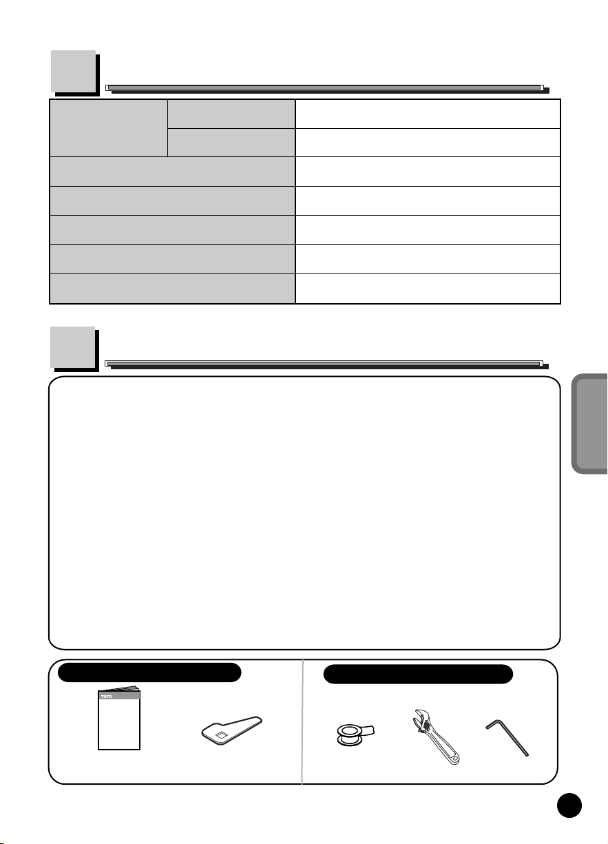
Please find these in the package.
Installation &
Owner’s manual
Open/close jig
Tools you will need for installation
Pipe Tape
Adjustable Wrench
Allen Wrech
2
Page 4
*Some parts may differ from the illustration depending on the model.
Thermostatic
Mixing Valve
Trim
Thermostatic
Mixing Valve
(Sold
ENGLISH
Separately)
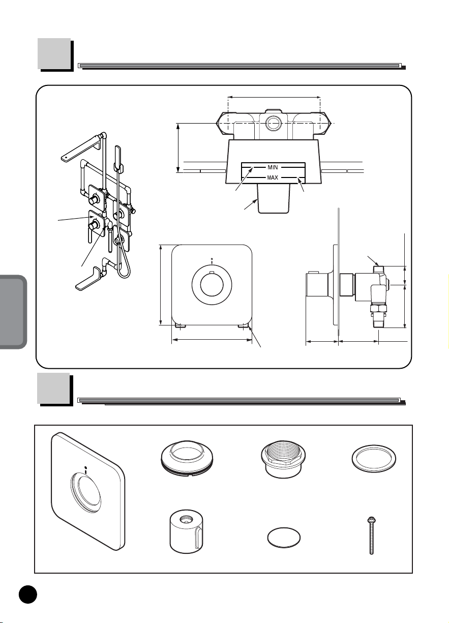
Set-Up Drawing
2-15/16” (75mm) MIN
3-9/16” (90mm) MAX
HOT
COLD
Lower limit
Guard Cover
4-15/16” (125 mm)
HOT to COLD supply
Upper limit
FINISHED
WALL
1/2” NPT
FINISHED
WALL
1-1/2”
(38 mm)
Complete Shower Set
6-5/16” (160 mm)
6-5/16” (160 mm)
1/2” NPT
Components
Check that you have the following parts.
escutcheon
coverplate
handle
*Some parts may differ from the figures depending on the model.
3
coverplate
nut
Cap
2-9/16”
65 mm
2-15/16” (75mm) MIN
3-9/16” (90mm) MAX
coverplate
gasket
Screw
3-3/8”
(85 mm)
Page 5

Installation Procedure
Some parts differ from the illustration depending on the model and depending on
set up option (Refer to page 5).
Showerhead
(Sold separately)
(Sold separately)
Dual Volume Control
Trim_Hand Shower
(TS170A
)
Dual Volume Control
Valve
(TSKD
)
Thermostatic Mixing
Valve Trim
(TS170T
)
TS170A
7-7/8”
(200 mm)
(TS170F
Bath Spout
(Sold separately)
TS170A
(Sold separately)
Single Volume Control
Trim_Hand Shower
(TS170A
)
Dual Volume Control
Valve
(TSKA
)
(Sold separately)
Hand Shower Trim
(handshower and trim)
)
7-7/8”
(200 mm)
55” (1400 mm)
39”(1000 mm)
83” (2100 mm)
ENGLISH
Thermostatic Mixing
Valve
(Sold separately)
1
(TSKT
)
Finish the wall.
4
connect valves
with 1/2” pipe
Install
5
the Trims
3
Connect Hot/Cold
Water Supply Lines
Refer to the respective
manual for each item
for Step 1 to Step 4.
FLOOR
Clean water supply
pipes by draining
FLOOR
FINISHED
23-1/4” (590mm)
WALL
Plumbing Setup
HOT
COLD
1/2” pipe
Single Vol
Control
Valve
Hand Shower
Adapter
Showerhead
Dual Vol
Control
Valve
Thermostatic
Mixing Valve
(TRIM is to be installed here.)
2
Wall Spout
Each item is
sold separately.
4
Page 6

Installation of the Trim
(Stem Adapter, Limiter Collar and Temperature Limiter)
①
ENGLISH
Caution
Trim installation should not be begun until the
followings are confirmed:
1) Checking the water flow
2) Checking the filters
Install the stem adapter into the valve as shown.
Confirm that distance between Finished Wall
and top of Limiter Collar is between 1” (25 mm)
and 1-3/8” (35 mm).
If not, Spacer should be removed as follow:
How to remove the Spacer
Stem Adjuster
Limiter Collar
1” (25 mm) MIN
1-3/8” (35 mm) MAX
Thermostatic
Mixing valve
Finished Wall
1) Take out the Stem Adjuster, unscrew the
Limiter Collar and pull out the Temperature
Limiter.
2) Then, Remove the Spacer as shown.
3) Attach the Temperature Limiter, making
sure that Circle Mark on the Limiter align
with middle top point of the valve.
4) Then, tighten the Limiter Collar and
reattached the Stem Adjuster.
Caution
1) Be sure to reattach the Temperature
Limiter.
2) Tighten the Limiter Collar firmly.
3) Make sure the Circle Mark points
upward.
5
Loosen.
Limiter Collar
Stem Adjuster
Tighten.
Limiter Collar
Stem Adjuster
Spacer
middle top point
Temperature
Limiter
Right above
Circle Mark
Temperature
Limiter
Page 7

Caution
Leave the guard cover on the valve till the tile work
is completed.
Pull out the guard cover before installing the trims.
Then, clean the tile.
Guard Cover
Installation of the Trim
(Coverplate, Escutcheon and Handle)
①
After cleaning the tile, place the coverplate in the
valve and install coverplate gasket and tighten the nut .
②
Confirm that coverplate is firmly installed with the nut.
Then, put on the escutcheon by pushing it into the
coverplate.
*If the escutcheon is not going in firmly, apply
soft soap on O-ring and try again.
NOTCH
Right below
Spline
③Confirm that distance between between
top of stem adapter and escutcheon is
1-3/8” (35 mm).
Stem
Adapter
④If not, use the Stem Adjustor provided and
adjust the stem adapter, making sure that
the distance is 1-3/8” (35 mm) as shown
in the picture.
⑤Make sure that “104” on the handle is in line
with Mark on the coverplate
1-3/8”
(35 mm)
escutcheon
handle
⑥Install the handle by using screw and put
the cap on.
Caution
Be sure to confirm that the gap is about 1/32” (1 mm).
If the gap is less than 1 mm, lower end of the handle and upper
end of the escutcheon will rub against each other, resulting in faulty
function.
Coverplate
coverplate
Gasket
escutcheon
Escutcheon
1/32”
(1mm)
Screw
Open/Close Tool
Mark
O-ring
longer
Stem
handle
Cap
Thermostatic
Mixing Valve
(SOLD SEPARATELY)
coverplate nut
stem
adjustor
shorter
Stem
"104"
Stem Adapter
ENGLISH
Holding
jig
Mark
6
Page 8

Installer should make sure that both filters in the valves
are clean.
If there are any dirt or debris in the filters, insufficient
water flow rate will be resulted.
ENGLISH
Filters should be cleaned in a regular basis with a
professional assistance.
Check the Product
1.Checking the water flow
After installation, check if water flows out by turning on the
Volume Control Handles.
Confirm that water comes out of all outlets and volume
control handles funstion well.
2.Cleaning the filter
screw driver
filter/check
valve
brush
unscrew
filter
filter
Before Use
Confirm the temperature of the water output.
1) Set the temperature control handle in the Mark at
“104” and confirm that output temperature is 104°F.
2) If temperature output is not 104°F, following adjustment
should be done.
To prevent scalding, the recommended hot water
temperature is 140°F (60°).
Confirming the outlet temperature and calibrating the valve
is required to minimize the risks of scalding.
After calibrated, the outlet temperature must read 104°F while
the temperature control handle knob is in the middle.
7
Volume
Control
Handle
KNOB
Handle
HOT
COLD
about 104°F
Page 9

Please see following instruction on how to adjust the output
temperature if it is shown incorrectly in the previous step.
1) Keep turning the temperature control handle to the
Hot side while reading a temperature indicator.
Stop turning it when the indicator reads 104°F.
2) Let the water run while removing the
temperature control handle by taking off the cap
and unscrewing the screw.
3) Make sure that “104” on the handle is in
line with Mark on the coverplate and
reattach the temperature control handle.
4) Put the screw and cap on and, again, confirm the
output water temperature, making sure that it is 104°F
in the middle.
Temperature
Control Handle
Screw
Calibrating the valve
calibrating the valve will be required if following the above
instructions do not result in correct remperature reading.
1) Shut of the HOT and Cold water supply
at the service stops.
Loosen.
2) Remove the Stem Adjuster, Limiter Collar
and temperature limiter.
Limiter Collar
3) Check to make sure that Circle Mark on
the temperature limiter align with middle
top point of the valve.
Stem Adjuster
Mark
"104"
Cap
Spacer
ENGLISH
middle top point
Temperature
Limiter
Right above
Circle Mark
4) Reinstall the limiter and collar and turn on t
he water supply.
Tighten.
5) Turn the water on and let it run for about
1 minute. Place a thermometer in the water
stream while truning the handle to the HOT
side. Stop when it reads 104°F (40°C).
Limiter Collar
Temperature
Limiter
Stem Adjuster
6)Let the water run at 104°F (40°C) water
temperature and then install the handle and cap.
NNOTE: If the valve turned accidently, repeat the calibration procedure.
8
Page 10

Maintenance
For performance and cleanliness, please maintain the product everyday.
Using a Cloth to Clean
●Slightly dirty
●Seriously dirty
ENGLISH
Use water and a damp cloth to wipe away the
dirt completely.
Use cloth with dilute detergent to wipe away
the dirt, then wash and dry it.
Notes:
Do not use the following materials
●Acidic cleaning agents, alkaline cleaning agents, or
bleaches that are not TOTO scale cleaner.
●Solvents like thinner and benzene
●Cleaning agents like cleanser or grinding powder
which contain coarse particles
●Nylon scrubbers and brushes
Troubleshooting
1
Is there looseness on the coverplate
or the handle?
coverplate
Confirm the Installation Procedure and check the
items.
Check looseness
temperature
control handle
Check Flow rate & temperature
2
Is the flow too small or temperature cannot be
adjusted easily ?
Product #
Filter/Check Valve
1) Check the filters and clean them as necessary,
(Refer to “Check the Product” for details.)
2) Check the shut-off valve and make sure that
Hot water
stop valve
Cold water
stop valve
both are fully opened.
9
Page 11

Set-Up Options
Showerhead
TS170A#CP
Bath Spout
TS170E#CP
Hand Shower Trim
1) Complete Set
Showerhead
Dual Vol
Control
Trim &
valve
Mixing
Valve Trim
& valve
Bath Spout
Replacement Part
Single Vol
Control Trim
& valve
Handshower
Adapter
Handshower
Trim (Trim &
Handshower)
Product
Description
Single Volume
Control Trim for
Hand Shower
Hand Shower
Dual Volume
Control Trim
2) w/o Handshower
Showerhead
Dual Vol
Control
Trim &
valve
Mixing
Valve Trim
& Valve
Bath Spout
Part
Number
TS170F#CP
TS170C1#CP
Adapter
TS170D#CP
TSKH
3) w/o wall spout
Showerhead
Handshower
Dual Vol
Control
Trim &
valve
Mixing
Valve Trim
& valve
Single Vol
Control
Trim & valve
Handshower
Trim (Trim &
Handshower)
Product
Product
Description
Description
Thermostatic
Mixing Valve Trim
SMA Thermostatic
Mixing Valve
Single Volume
Control Trim for
Head Shower
Single Vol
Control Valve
Dual Volume
Control Valve
Handshower
Adapter
TS170T#CP
TS170C#CP
Part
Number
TSKT
TSKA
TSKD
4) Showerhead only
Showerhead
4
Single
Vol Control
Trim
&
valve
Mixing
Valve Trim
& valve
#CP = Polished Chrome
ENGLISH
No. Description
HANDLE CAP
1
O RING
2
SCREW
3
HANDLE
4
HANDLE KNOB RING
5
6
ESCUTCHEON
7
O RING
O RING
COVERPLATE NUT
8
COVERPLATE GASKET
9
COVERPLATE
10
COVERPLATE PACKING
11
(SPECIFY THE MODEL#)
10
9
7
5
8
11
6
2
4
3
1
10
Page 12

Warranty
LIFETIME LIMITED WARRANTY
Warranty applies to selected residential faucets only.
1. TOTO
during normal residential use for as long as the original consumer end-user purchaser owns their home. This
limited lifetime warranty is extended only to the original consumer end-user purchaser and only so long as
the Product remains in use by the original consumer end-user purchaser in its original place of installation in
the purchaser’s residence. This warranty applies only to Product purchased and installed in North America.
2. TOTO® obligations under this warranty are limited to repair or replacement, at TOTO®’s
option, of Product or parts found to be defective in normal residential use, provided that such Product was
properly installed and used in accordance with the owner’s manual. TOTO
inspections as may be necessary in order to determine the cause of the defect.
3. This warranty does not apply to the following items:
Damage or loss sustained in a natural calamity such as
etc.
Damage or loss resulting from any accident, unreasonable use, misuse, abuse, negligence, or improper
care, cleaning or maintenance of the Product.
Damage or loss resulting from sediments or foreign matter contained in a water system.
Damage or loss resulting from improper installation or from installation of the Product in a harsh and/or
hazardous environment, or improper removal, repair or modi cation of the Product.
Damage or loss resulting from the use of an abrasive cleanser.
4. If the Product is used commercially, TOTO
materials and workmanship for one (1) year from the date the Product is installed, with all other terms of this
warranty applicable except the duration of the warranty.
5. THIS WARRANTY GIVES YOU SPECIFIC LEGAL RIGHTS. YOU MAY HAVE OTHER
RIGHTS, WHICH VARY FROM STATE TO STATE OR PROVINCE TO PROVINCE.
6. To obtain warranty repair service under this warranty, you must take the Product or deliver it prepaid to
a TOTO® service facility with proof of purchase (original sales receipt) together with a letter stating the
problem, or contact a TOTO® distributor or products service contractor, or write directly to TOTO
INC., 1155 Southern road, Morrow, Georgia 30260, (888) 295-8134. If, because of the size of the Product
or nature of the defect, the Product cannot be returned to TOTO®, receipt by TOTO® of written notice of the
defect together with proof of purchase (original sales receipt) shall constitute delivery. In such case, TOTO
may choose to repair the Product at the purchaser’s location or pay to transport the Product to a service
facility.
THIS WRITTEN WARRANTY IS THE ONLY WARRANTY MADE BY TOTO
REPLACEMENT OR OTHER APPROPRIATE ADJUSTMENT AS PROVIDED UNDER THIS
WARRANTY SHALL BE THE EXCLUSIVE REMEDY AVAILABLE TO THE ORIGINAL
PURCHASER. TOTO® SHALL NOT BE RESPONSIBLE FOR LOSS OF THE PRODUCT OR FOR
OTHER INCIDENTAL, SPECIAL OR CONSEQUENTIAL DAMAGES OR EXPENSES INCURRED
BY THE ORIGINAL PURCHASER, OR FOR LABOR OR OTHER COSTS DUE TO INSTALLATION
OR REMOVAL, OR COSTS OF REPAIRS BY OTHERS, OR FOR ANY OTHER EXPENSE NOT
SPECIFICALLY STATED. IN NO EVENT WILL TOTO®’S RESPONSIBILITY EXCEED THE
PURCHASE PRICE OF THE PRODUCT. EXCEPT TO THE EXTENT PROHIBITED BY APPLICABLE
LAW, ANY IMPLIED WARRANTIES, INCLUDING THAT OF MERCHANTABILITY OR FITNESS
FOR USE OR FOR A PARTICULAR PURPOSE, ARE EXPRESSLY LIMITED TO THE DURATION OF
THIS WARRANTY. SOME STATES AND PROVINCES DO NOT ALLOW LIMITATIONS ON HOW
LONG AN IMPLIED WARRANTY LASTS, OR THE EXCLUSION OR LIMITATION OF INCIDENTAL
OR CONSEQUENTIAL DAMAGES, SO THE ABOVE LIMITATION AND EXCLUSION MAY NOT
APPLY TO YOU.
®
warrants its faucets (“Product”) to be free from defects in materials and workmanship
®
reserves the right to make such
fire, earthquake,
®
warrants the Product to be free from defects in
flood, thunder, electrical storm,
®
U.S.A.,
®
. REPAIR,
®
©2007 TOTO USA, Inc. á 1155 Southern Road, Morrow GA 30260
Phone (888)-295-8134 Fax (800)-699-4889 www.totousa.com
TOTO USA, INC. is a wholly owned subsidiary of TOTO Ltd.
Printed in August, 2007
0GU3036
 Loading...