

Toto TET1LAR, TET1UAX, TET1LAX, TET1UAR, TEU1GAR Installation And Owner's Manual
...
Installation and Owner’s Manual
Manual de Instrucciones y del Propietario
Manuel d’Installation et d’Utilisation
Manual de Instalação e do Proprietário
EcoPower Flush Valve
Fluxómetro EcoPower
Valve de Chasse EcoPower
Fluxómetro Self Power
Warranty Registration and Inquiry
For product warranty registration, TOTO U.S.A. Inc. recommends online warranty registration. Please visit our web site
http://www.totousa.com.If you have questions regarding warranty policy or coverage, please contact TOTO U.S.A. Inc.,
Customer Service Department, 1155 Southern Road,Morrow, GA 30260 (888) 295-8134 or (678) 466-1300 when calling
from outside of U.S.A.
2
TABLE OF CONTENTS
Thanks for Choosing TOTO!...................................................................................................................2
Included Parts.............................................................................................................................................2
Common Tools Needed............................................................................................................................3
Features..................................................................................................................................3
Specifications..........................................................................................................................
Technical Information.................................................................................................................................5
ENGLISH
Warnings....................................................................................................................... ...................6
Before Installation.......................................................................................................................................6
Installation Procedure...............................................................................................................................7
Test Run.....................................................................................................................................................10
Note to the Installer..................................................................................................................................10
Periodic Maintenance...............................................................................................................................10
Care & Cleaning........................................................................................................................................10
Using the Flush Valve.............................................................................................................................11
Troubleshooting.................................................................................................................................12
Warranty.........................................................................................................................................16
Rough-In Dimensions...............................................................................................................................62
Reclaimed Water Specifications..............................................................................................................64
THANKS FOR CHOOSING TOTO!
The mission of TOTO is to provide the world with healthy, hygienic and more comfortable
lifestyles. We design every product with the balance of form and function as a guiding principle.
Congratulations on your choice.
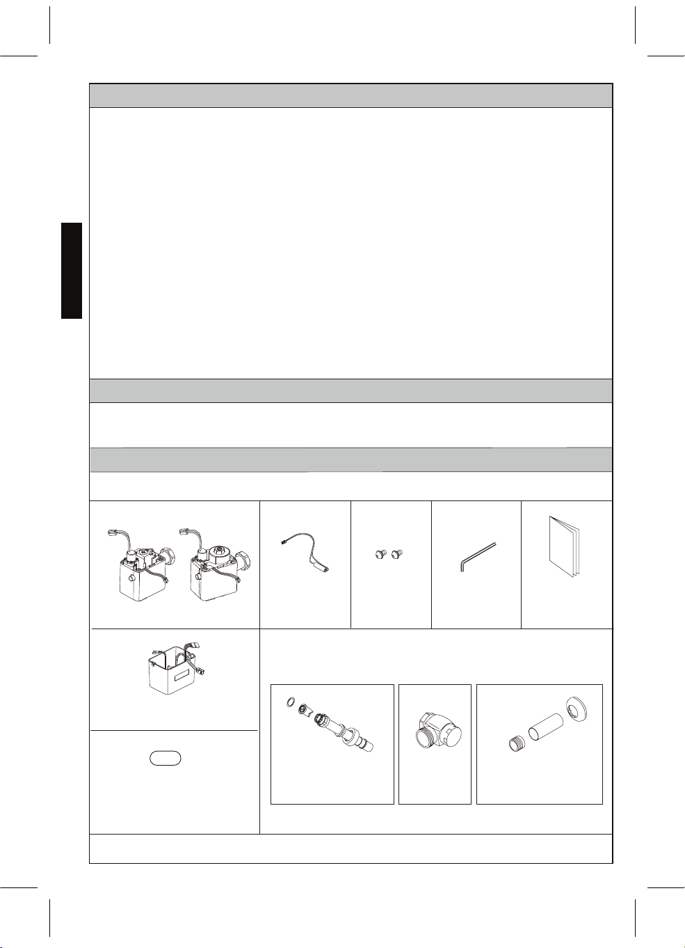
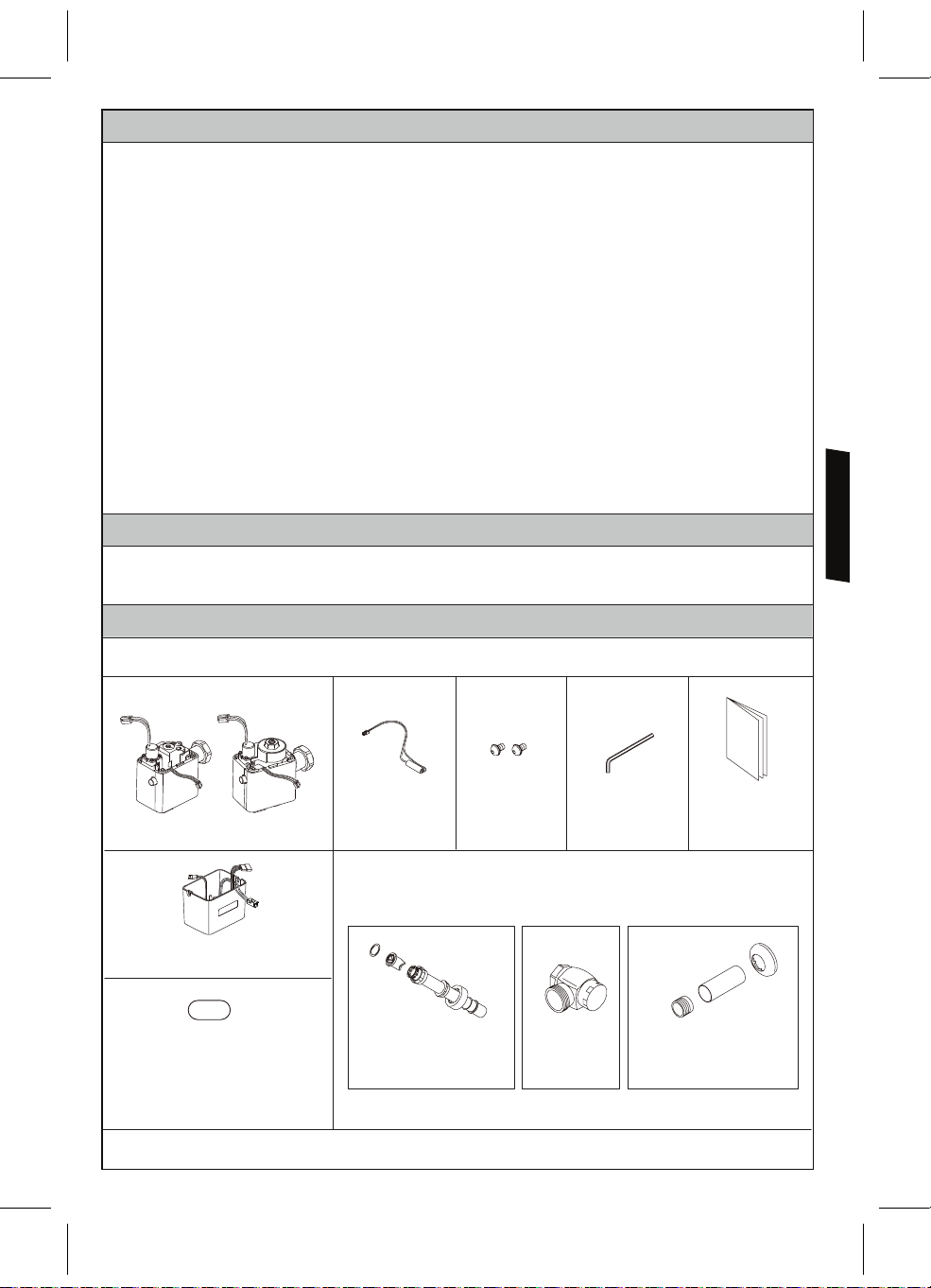
INCLUDED PARTS
Check to make sure you have all these parts from the package*:
3............................................................................................................ tcudorp rewopocE eht gnizilaitinI
4
TEU1UA(R)(X)
*Appearance of some components may vary depending on the model.
all valves except for
TEU1UA(R)(X)
Valve body assembly
Top cover assembly
Flush valve
Notice label
Battery Pack
For TEU1UA(X)12, TEU1LA(X)(12,22),TEU1GA(12,22), TET1UA(X)32,
TET1LA(X)32, TET6LA(X)32, TET1GA32, TET6GA32,
Vacuum breaker tube
(with spud joint)
ScrewsBack-up
Control stop Sweat solder kit
Hex wrench Installation and
(Escutcheon, covering tube,
Adapter)
Owner's Manual
TET6UA(X)32
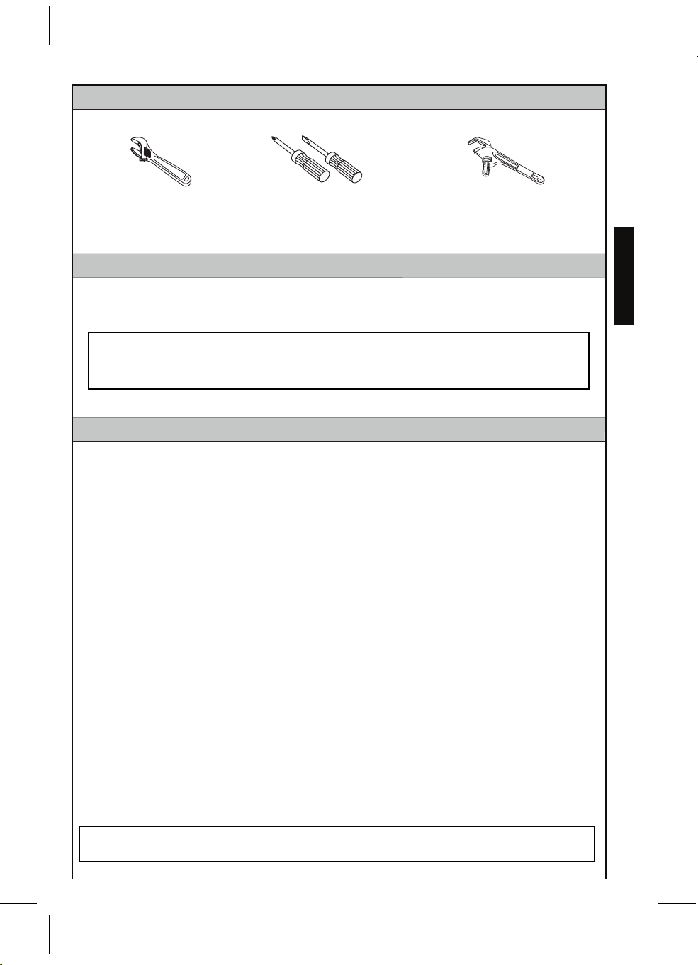
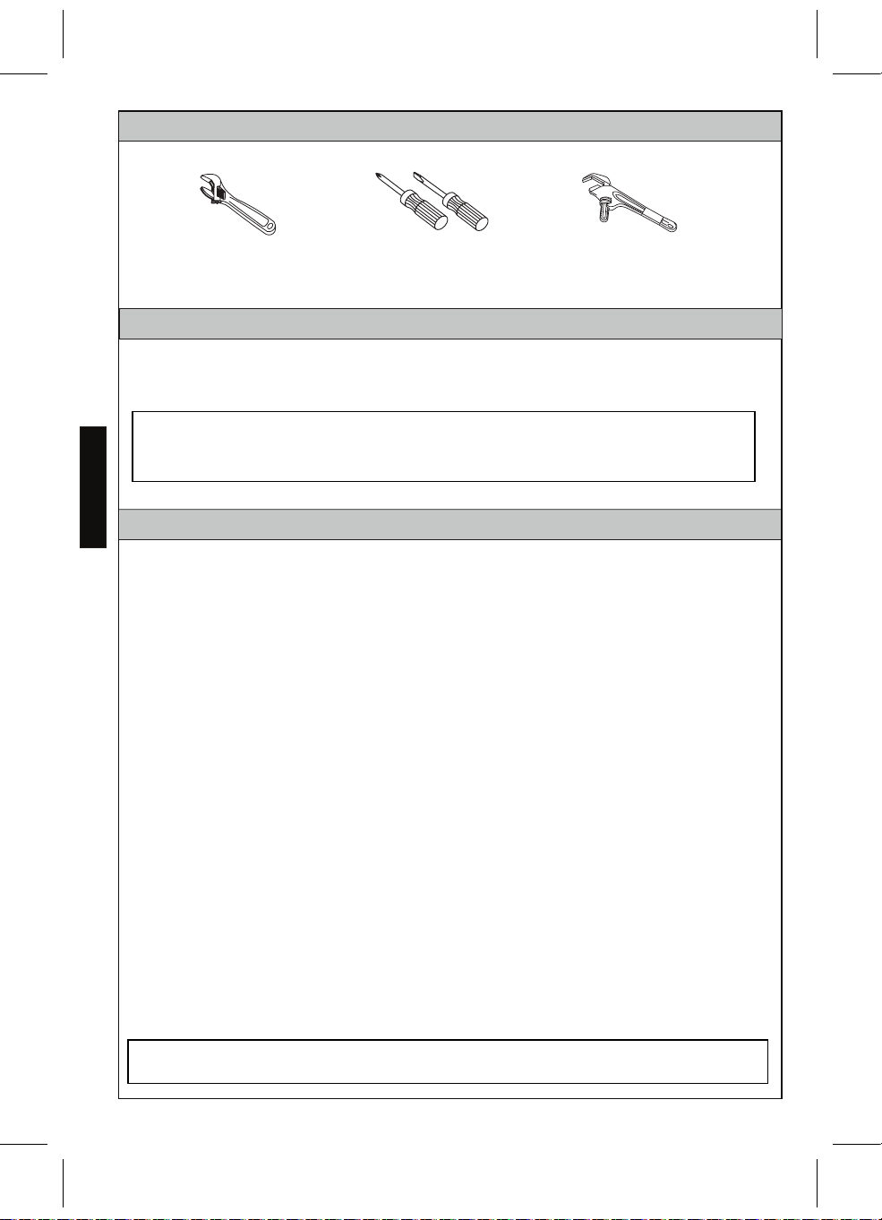
COMMON TOOLS NEEDED
3
Adjustable wrench
Screwdrivers (Phillips and Slotted )
Offset pipe wrench
INITIALIZING THE ECOPOWER PRODUCT
Thank you for choosing the latest innovation in low power consumption EcoPower products.
Please note below the duration of time required to initialize the electronics.
It will take approximately 5 minutes after connecting the battery for the electronics to initialize.
This delay is a normal part of startup.
After approximately 30 seconds, the sensor LED will start flashing in 4 second intervals until
the initialization is complete.
FEATURES
Fully Automatic and Hygienic
The EcoPower Flush Valve uses an infrared sensor to detect the user using and departing the
fixture, to provide an automatic flush of the fixture after a short delay. No manual operation is
required, improving the experience of use and hygiene of the fixture.
System Protection Timer
When the fixture is not used for 24 hours (12 hours for TEU1LA(R)(X) and TEU1UA(R)(X)) the
protection timer commands the system to flush in order to maintain the trap seal.
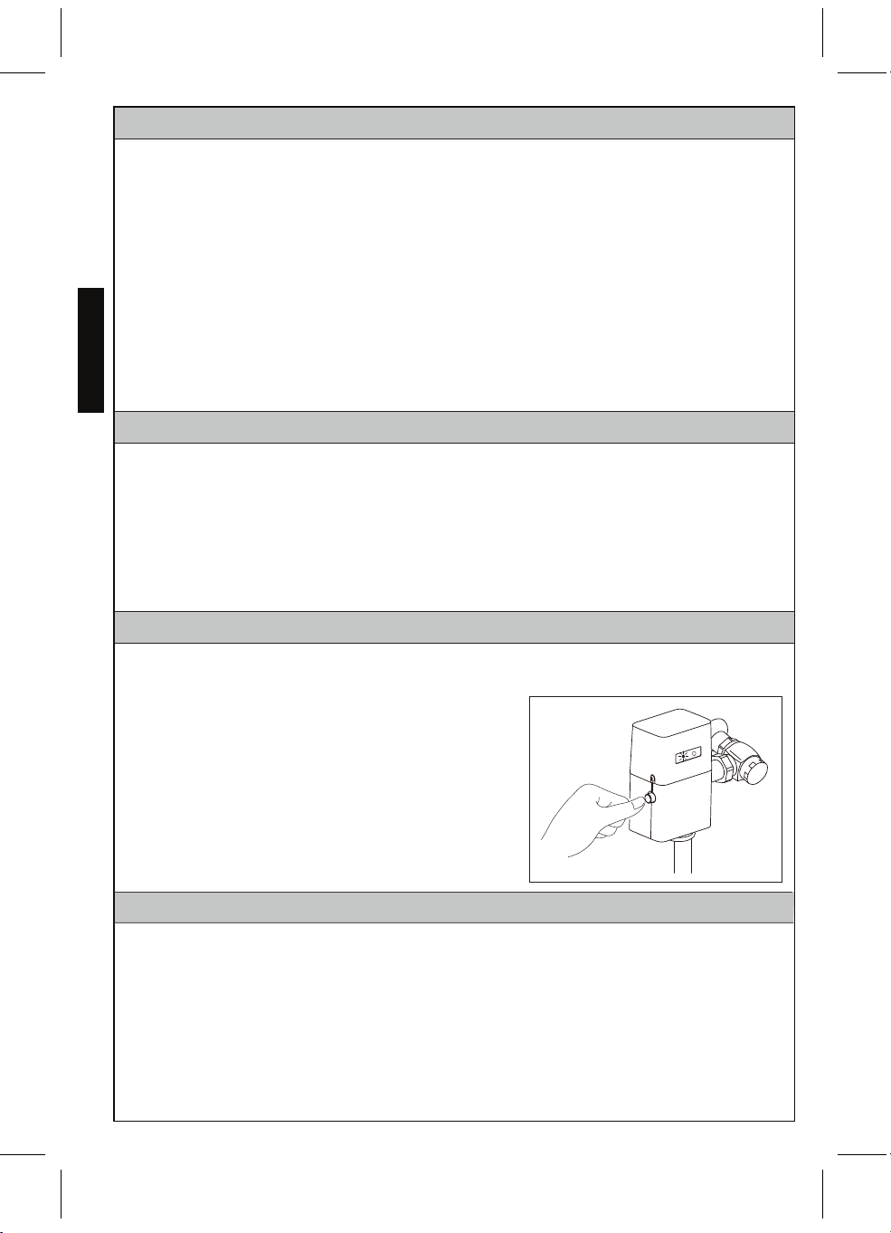
Manual Functionality
For maintenance and emergency use, the EcoPower Flush Valve is equipped with a manual
flushing button.
Green Features
Conserves Power
The flushing of the fixture activates a hydropower generator which generates electric power for
the next flush. (See About TOTO’s Hydropower Generator, page 5)
Conserves Water
Two functions help the EcoPower Flush Valve conserve water:
Fuzzy Logic Control
The EcoPower Flush Valve can sense how often and how long the fixture has been used to
deliver the correct amount of water. (See About Fuzzy Logic Control, page 5)
Anti Consecutive Flushing
The EcoPower Flush Valve offers water saving consecutive flush prevention. After a flush, the
valve will not automatically flush again for 10 seconds for urinals and 30 seconds for toilets.
ENGLISH
TOTO EcoPower Flush Valve are designed to work for 10 years, under normal conditions, with no
minimum usage required.
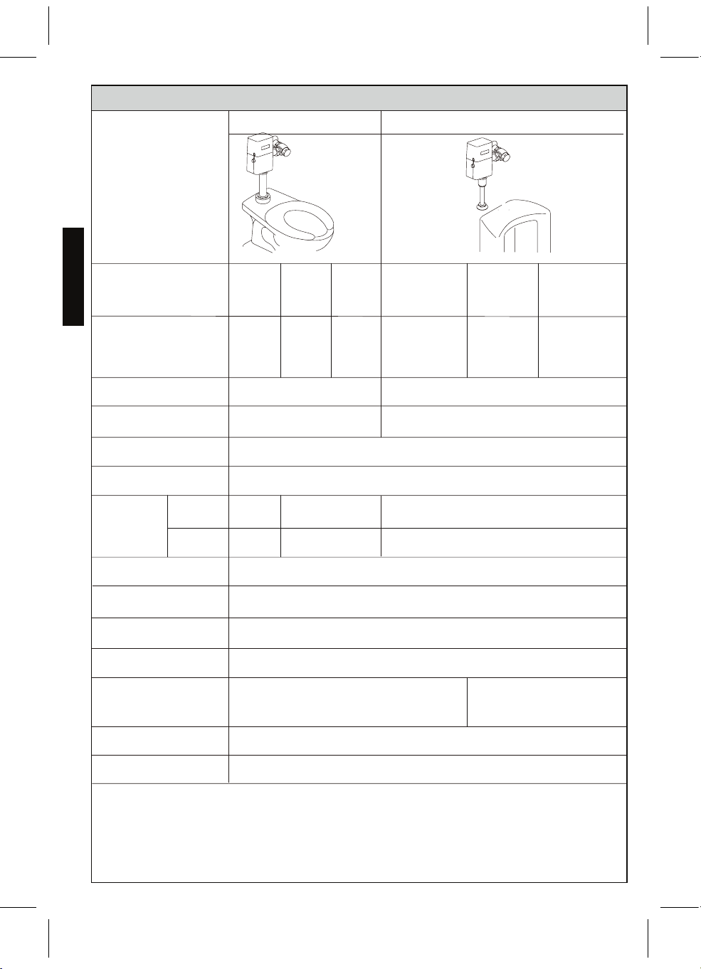
SPECIFICATIONS
4
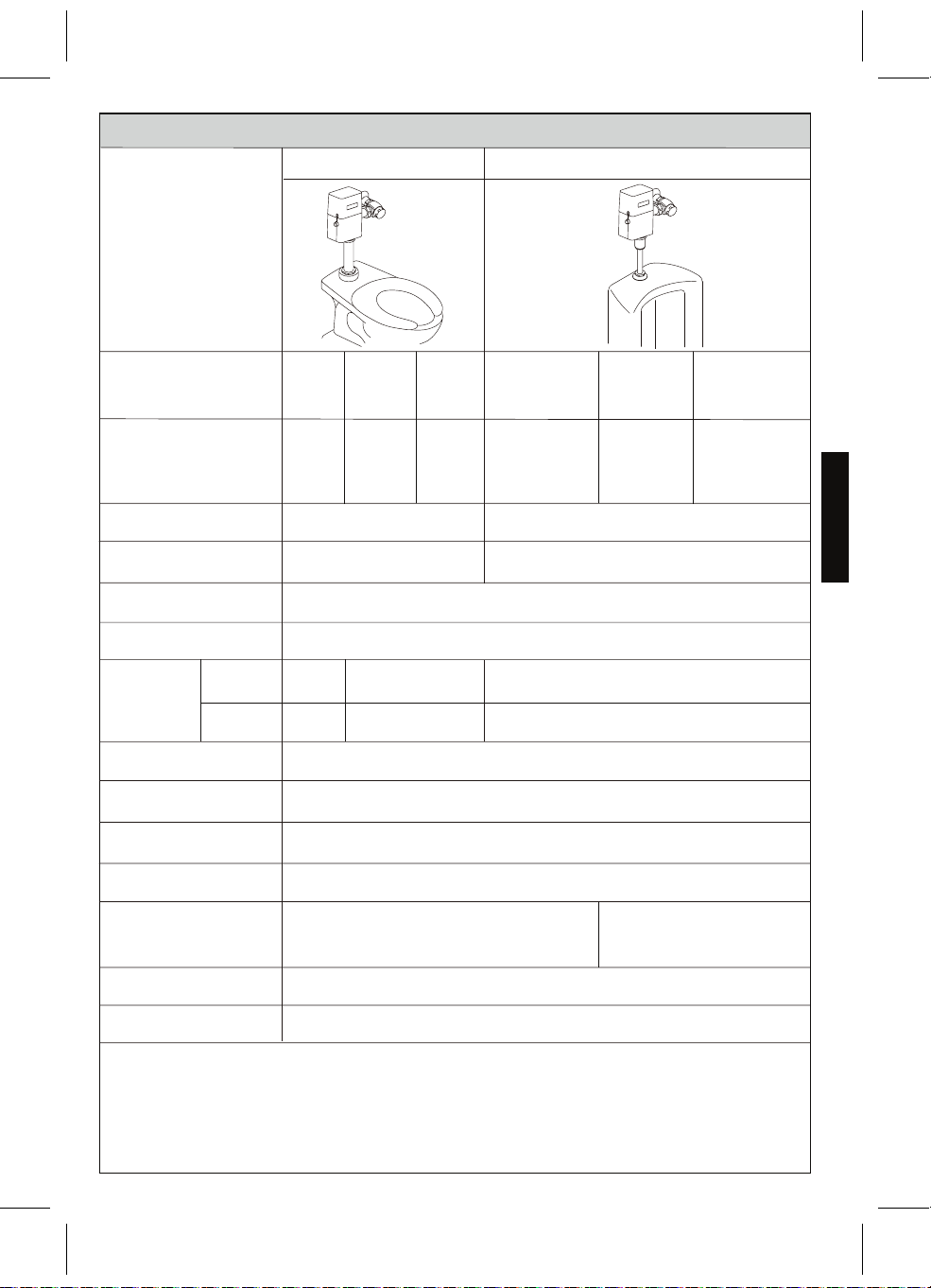
Toilet Urinal
Figure
ENGLISH
Model Number
Rated Flush Volume
Toilet/Urinal type
Control stop inlet
Flush Valve inlet
Flush Valve outlet
Min
Supply water
pressure
(Flowing)
Max*
(Static)
Shutoff pressure
Dimension of cover
Detection range
from the front
Detection time
TET1GAR
TET6GAR
1.6 G
15 psi
(103 kPa)
125 psi
(862 kPa)
TET1LAR
TET1LAX
TET6LAR
TET6LAX
1.28 G
(6 L)
(4.8 L)
Flush Valve type bowl
1"NPT 3/4"NPT
TET1UAR
TET1UAX
TET6UAR
TET6UAX
1 G
(3.8 L)
35 psi
(241 kPa)
125 psi
(862 kPa)
7" (H) x 4-9/16"(W) x 3-3/16"(D)
(178 mm (H) x 115 mm (W) x 81 mm (D))
TEU1GAR
fuzzy logic
adj. flush vol.
0.5 G (1.9L)
typical flush vol.
1.0 G (3.8 L)
1-1/4"NPSM
1-1/2"NPSM
7 psi (48 kPa)
Within 33-1/2" (850 mm)
6 seconds
TEU1LAR
TEU1LAX
0.5 G (1.9 L)
Wash down flush
15 psi (103 kPa)
125 psi (862 kPa)
TEU1UAR
TEU1UAX
0.125 G (0.47 L)
Trap seal protection
Ambient temperature
Water temperature
NOTE:
The type of fixture determines the minimum pressure required for the valve. Consult
fixture manufacturer for the pressure requirement. TET6LA(R)(X), TET6GAR, and TET6UA(R)(X)
require 24" OR LONGER vacuum breakers. The valve will not have the proper detection range
if you use a shorter vacuum breaker.
* Water pressures over 80 psi are not recommended for most plumbing fixtures.
Automatic flush every
24 hours of non-use
32-104˚F (0-40˚C)
34-104˚F (1-40˚C)
Automatic flush every
12 hours of non-use
Controller
TECHNICAL INFORMATION
5
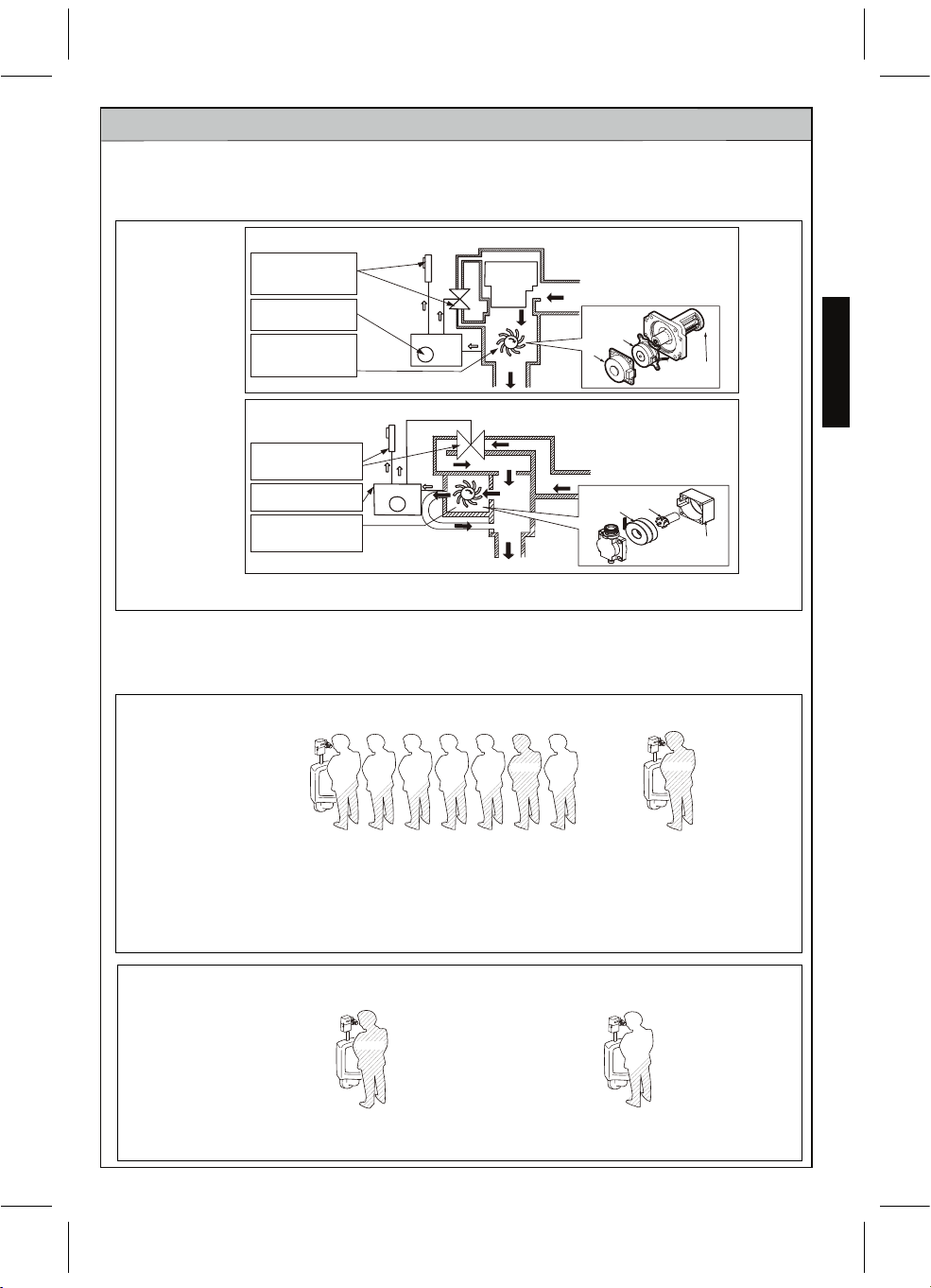
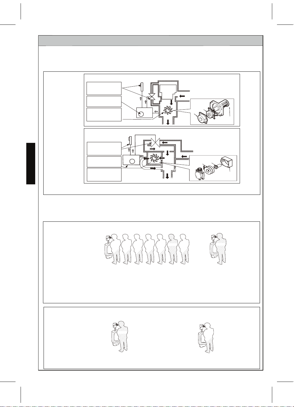
About TOTO's Hydropowered Generator
The flow of water causes the turbine in the power generator to rotate. This process generates
electric power and enables the automatic Flush Valve to operate. See ill. 1 below.
TET1GAR
TET6GAR
TEU1GAR
TET1LA(R)(X)
TET6LA(R)(X)
TEU1LA(R)(X)
TET6UA(R)(X)
TET1UA(R)(X)
citamotuA ehT )3
Flush Valve uses the
charged power.
stored in a capacitor.
generate electric
power.
si rewop cirtcelE )2
Sensor eye
Flush Valve
Piston
Water supply
ot setator enibrut A )1
Controller
Cover
Coil
Turbine
ENGLISH
TEU1UA(R)(X)
3)
The Automatic
Flush Valve uses the
charged power.
2)
Electric power is
stored in a capacitor.
1)
A turbine rotates to
generate electric
power.
Sensor eye
Flush Valve
Water supply
Coil
Turbine
Cover
ill. 1 Hydropowered Generator
About Fuzzy Logic Control (TEU1GAR only)
The Fuzzy Logic Control function automatically adjusts the discharge of water according to the
frequency and duration of usage (see ill. 2 and ill. 3).
The Fuzzy Logic
Control system judges
the frequency of
usage by the idle time
of the fixture and
causes the Flush Valve
to discharge water in
an optimal flushing
pattern.
High Frequency of Usage Low Frequency of Usage
Less Less Less Less Less LessTypical
If the idle time is short, the system assumes frequent use
and the Flush Valve discharges less water.
Examples of high frequency use would be during a lunch
break or an intermission in a movie theatre.
If the idle time is long, the system
assumes infrequent use, causing the
Flush Valve deliver a typical quantity of
water for thorough flushing.
Examples of low frequency use would be
during after hours at the office or a slow
day at the park.
Typical
ill. 2 Frequency of Usage
The Fuzzy Logic Control
system predicts the
quantity of flush water
needed based on the
user's duration of use.
Long duration of usage Short Duration of Usage
A long duration of use indicates
Typical
there may be more to flush,
requiring the Flush Valve to
deliver a typical quantity of flush
water for thorough flushing.
A short duration of use
Less
indicates there may be
less to flush, requiring the
Flush Valve to discharge
less flush water.
ill. 3 Duration of Usage

WARNINGS
6
Please read and adhere to these notes. Failure to do so could
result in personal injury and/or property damage.
Never splash water on the controller. The EcoPower Flush Valve is an electric appliance.
Risk of product malfunction.
Do not strike or kick the EcoPower Flush Valve. Risk of product malfunction or water leakage.
ENGLISH
Do not use the EcoPower Flush Valve at temperatures exceeding what local codes or
product specification allow. Risk of product malfunction.
Do not place an item in a room with high humidity such as shower area or sauna. Risk of
product malfunction.
Never attempt to disassemble, reassemble, repair or modify the EcoPower Flush Valve
unless you are a professional. Risk of product malfunction and electric shock.
Do not use standard vacuum breaker or control stop with reclaimed water flush valve.
Do not use petroleum based products or pipe sealants, doing so could damage product and
cause water damage.
BEFORE INSTALLATION
IMPORTANT: Plumbing installation must be in accordance with applicable codes and
regulations. Water supply lines must be sized to provide an adequate volume of water for
each fixture. Flush all waterlines prior to operation.
Toilet and urinal Flush Valves are not interchangeable, check the model number on the label to
make sure you have the correct type. Toilet Flush Valve model numbers begin with ‘TET’ and
Urinal Flush Valve model numbers begin with ‘TEU’.
Prior to installing your Flush Valve, install the items listed below:
Bowl fixture/Urinal fixture
Drain line
Water supply line
The supply piping to these devices must be securely anchored to the building structure to
prevent the installed device moving during use. Prevent marring to the exposed surface
during installation.
flush valve to the bowl. Trapped air in supply lines may crack the china.
Except for TET6GAR, TET6UA(R)(X) and TET6LA(R)(X), install the Flush Valve so the control
stop is no less than 11-1/8” (282mm) above the top of the bowl/urinal. For TET6GAR,
TET6UA(R)(X) and TET6LA(R)(X), install the Flush Valve such the control stop is 27” (685.8mm)
above the bowl/urinal. see local codes for special requirements.
Avoid damaging the surface of the infrared sensor while unpacking.
For Toilet Flush Valve:
The toilet Flush Valve may not function if toilet seat or lid cover are left upright and block the
sensor.
For Urinal Flush Valve:
The urinal Flush Valve is designed for optimal performance with a washout urinal, but a
siphon jet urinal may be substituted. Blowout urinals are not recommended.
For Reclaimed Water Flush Valve:
Only use reclaimed water angle stop and vacuum breaker.
The detection range of the infrared sensor is shown on p.15.
To prevent valve malfunction, do not install a handrail or any other object within the detection
range of the sensor. Do not install the Flush Valve where sensor faces a mirror, stainless steel
wall, other highly reflective surfaces or another infrared sensor.
IMPORTANT: Purge all air from the supply lines before connecting
INSTALLATION PROCEDURE
NOTE: For retrofit installation, remove the old Flush Valve
after shutting off the control stop.
NOTE: For reclaimed water, do not use standard vacuum
breaker or control stop.
NOTE: Do not use petroleum based products or pipe
sealants.
U
E
M
L
O
-
B
R
T
E
P
E
S
U
T
O
N
O
D
A
A
S
E
D
S
E
A
L
A
N
T
S
T
!
N
T
E
O
I
N
T
ENGLISH
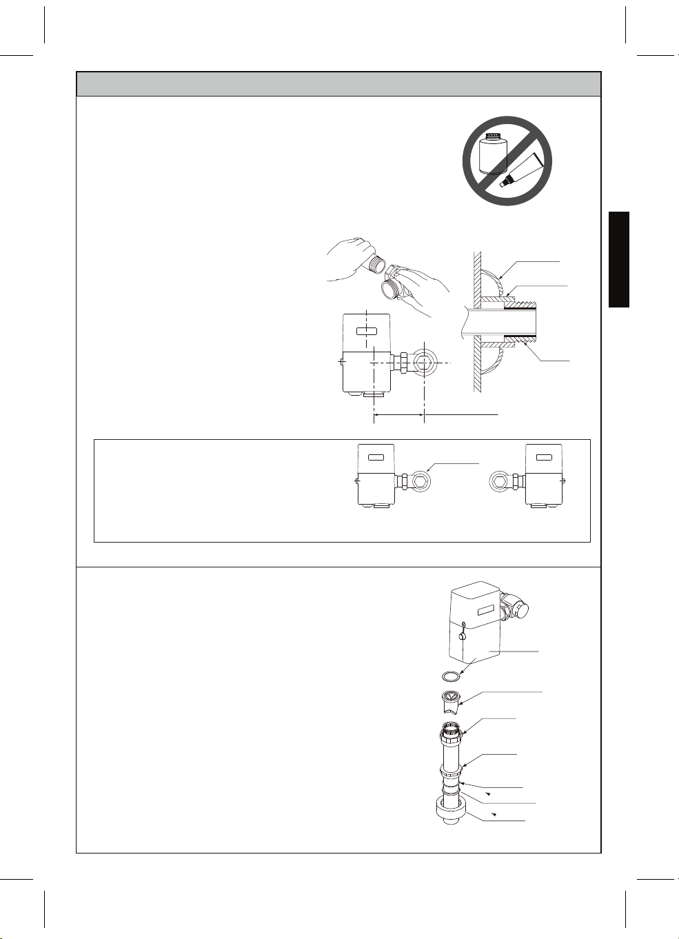
1. Install the control stop using an
appropriate size escutcheon and a
sweat solder
Thread sealing
adapter kit, if applicable.
compounds should be
used on male NPT threads only.
The distance from center of the control
stop to center of the Flush Valve
should fall within 4-1/4" to
5-1/4"(107mm to 133mm).
For use with a left water supply, attach
the sensor top cover in the opposite
direction so that the sensor will be at
the front.
2. Determine the length of vacuum
breaker tube to join the Flush Valve
and fixture spud. If required, cut the
vacuum breaker tube to the proper
length.
For sweat solder
Escutcheon
Covering tube
Adapter
Min.4-1/4"(107mm)
Max.5-1/4"(133mm)
Control stop
Right Water Supply Left Water Supply
Friction washer
3. Assemble the spud nut assembly to
the fixture spud. Hand tighten spud
nut to fixture.
Vacuum breaker
Tube nut
Spud nut
Slip gasket
Rubber gasket
Escutcheon
7
INSTALLATION PROCEDURE
8
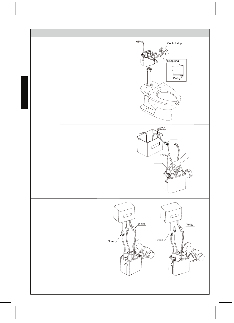
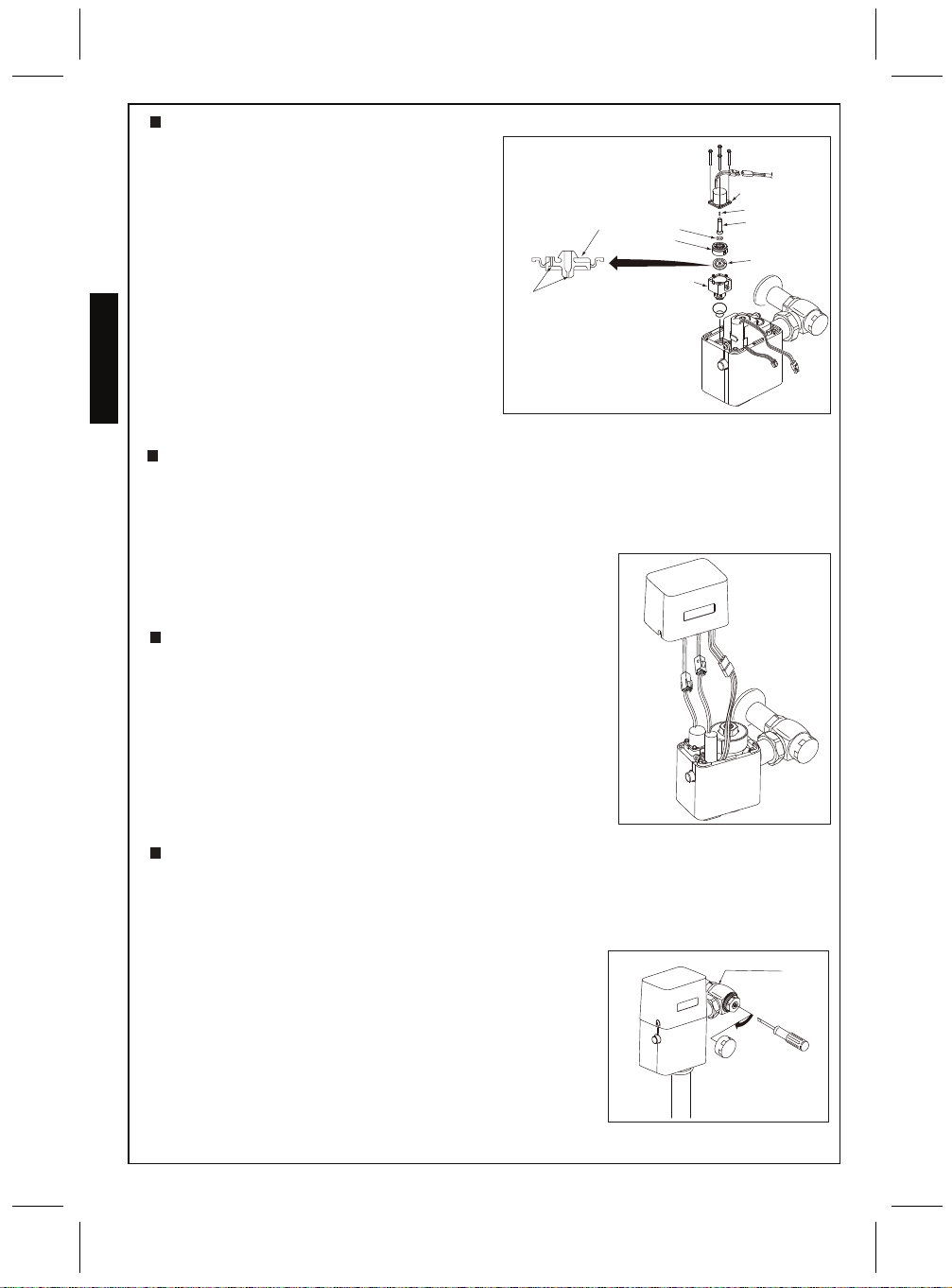
4. Prior to inserting the Flush Valve tailpiece into
the control stop, make sure that the o-ring is in
the groove at the end of the tailpiece, the
locking nut and the snap ring are located as
shown.
5. Connect the Flush Valve with the control stop
ENGLISH
and the vacuum breaker tube. Exercise care not
to damage the o-ring when inserting the
tailpiece into the control stop. If lubrication is
needed, wetting the o-ring with water is
sufficient.
6. Align the Flush Valve and securely tighten
fixture spud nut, vacuum breaker tube nut and
locking nut with a wrench.
7. Connect the battery cable with that of the
controller and set the battery at the proper
position.
It will take 5 minutes after connecting the
NOTE:
battery for the electronics to initialize.
After approximately 30 seconds, the
sensor LED will flash in 4 second intervals
until the initialization completes.
White
Battery
8. Connect the cables of the solenoid
valve and generator with those of
controller.
TEU1UA(R)(X)
all valves except for
TEU1UA(R)(X)
INSTALLATION PROCEDURE
9
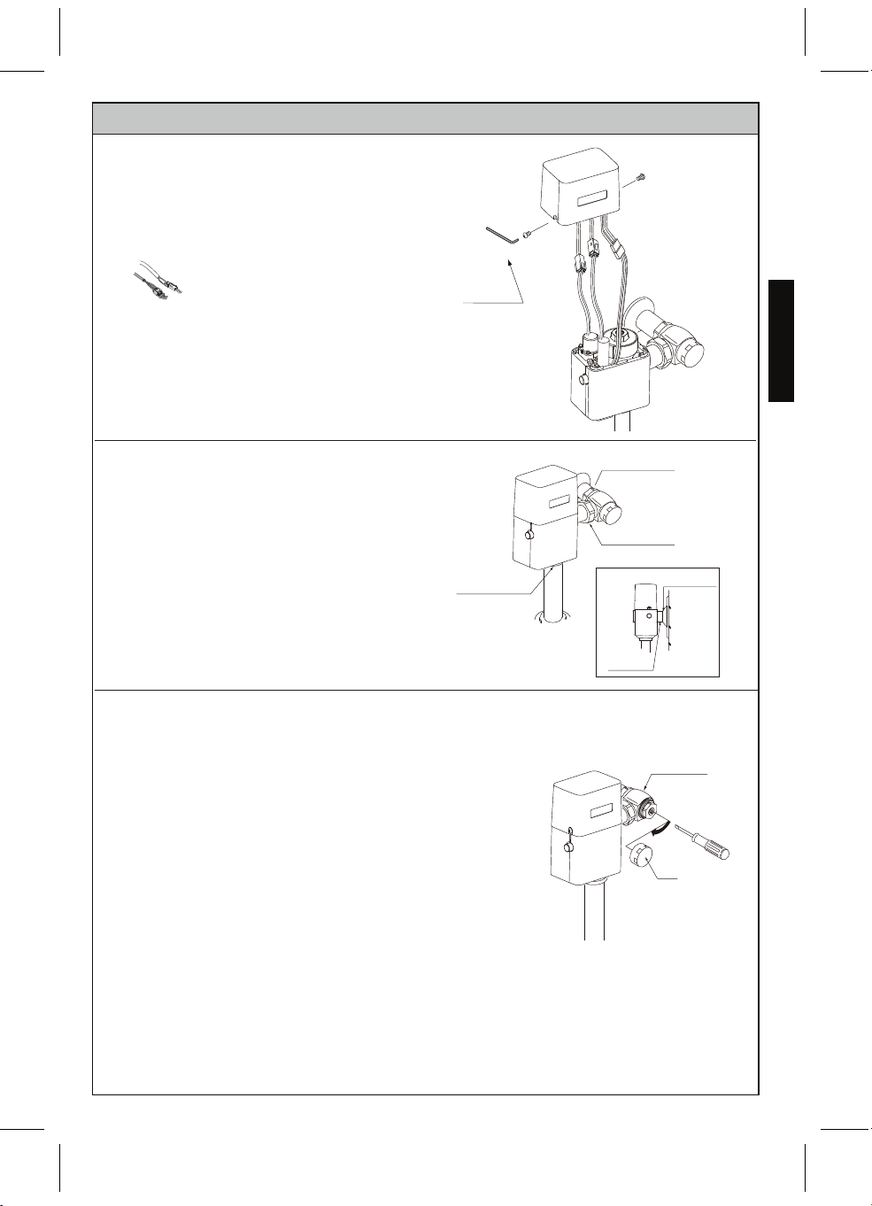
9. Fasten the sensor top cover to body
assembly with the supplied screws
and hex wrench.
Protect the wire connections
inside the top cover.
Hex wrench
ENGLISH
10. Before the supply water is turned on,
be sure all water leaks are eliminated
by tightening all the pipe connections.
NOTE: If for any reason it becomes necessary
to remove the control stop, make sure
the water is shut off at the main supply
valve.
Pipe connection
The Flush Valves are preset for fixture volume as marked on
the valve carton. The valve does not require adjustment for
variation in water pressure within its operating range.
11. To set the Flush Valve for proper operation, open the
control stop completely by using the adjusting screw.
12. Activate the Flush Valve several times.
13. In the case of excessive flow rate, gradually adjust the
control stop towards the closed position using the
adjusting screw, until there is suitable water flow into the
fixture.
14. The cap for the control stop should be placed after final
adjustments have been made.
15. Tighten the cap firmly with a wrench.
Pipe connection
Pipe connection
Escutcheon
Joint tube
Control stop
Cap
WARNING: Do not open the control stop to the point where the flow from the Flush Valve exceeds
the flow capability of the fixture. In case of a valve failure, the water must not overflow
from the fixture.
TEST RUN
10
After connecting the battery, the initialization process takes 5 minutes. After approximately 30
seconds, the sensor LED will start flashing in 4 second intervals until the initialization is
complete. Please wait before starting the Test Run.
1. For Toilet: Sit on the toilet seat.
For Urinal: Stand within two feet from the front of the Flush Valve.
2. Stay there for 6 seconds or more and then leave the toilet seat or the urinal. The valve
ENGLISH
should automatically flush, immediately for urinals and after 3 seconds for toilets.
3. Press the manual flushing button for 2 seconds and make sure the valve flushes properly
and the sensor red light of the sensor is on. To correct overflow from a urinal Flush Valve,
adjust the control stop clockwise.
4. Recheck all the pipe connections for water leaks. If the Flush Valve is not operating
properly following the test run consult the Troubleshooting section on p.12.
NOTE TO THE INSTALLER
After the Flush Valve unit has been installed correctly, please explain to your customer how to
use it and tell them to observe the following instructions:
1. Do not put any object in front of the sensor window which could obstruct the sensor,
causing it to malfunction.
2. In case of any trouble, consult the troubleshooting section on p.12. If you lack the necessary
skills required or have difficulty following the directions for installation, maintenance, repairs,
troubleshooting or adjustments of the product, do not proceed without help from a qualified
person to assist you.
PERIODIC MAINTENANCE
Please check your EcoPower Flush Valve at least once a month according to the following
instructions to avoid risk of property damage.
Check the piping to see whether there is any leakage.
Press the manual flushing button and make sure the
sensor red light is on for 2 seconds to see if the generator performs properly or not.
If the red light is not on, check the generator to see if
any debris is clogged up at the turbine.
CARE & CLEANING
IMPORTANT! Do not scratch the sensor or faceplate when cleaning.
Avoid using any cleaning materials that may scratch the surface.
Never use polishing powder, detergent that includes coarse particles, thinners, benzene,
acids, alkaline detergents, or nylon scrub brushes.
To safely clean the surface, wipe it using a dampened soft cloth with diluted dishwashing
detergent and dry it with another soft cloth. If this does not adequately clean the surface,
wipe the area with a neutral detergent and wet cloth.
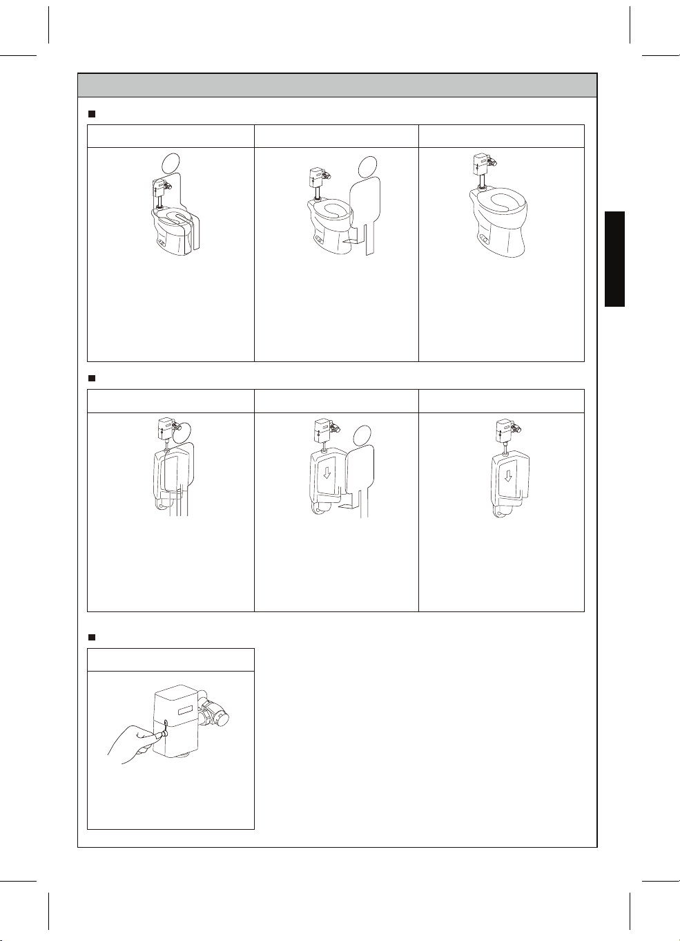
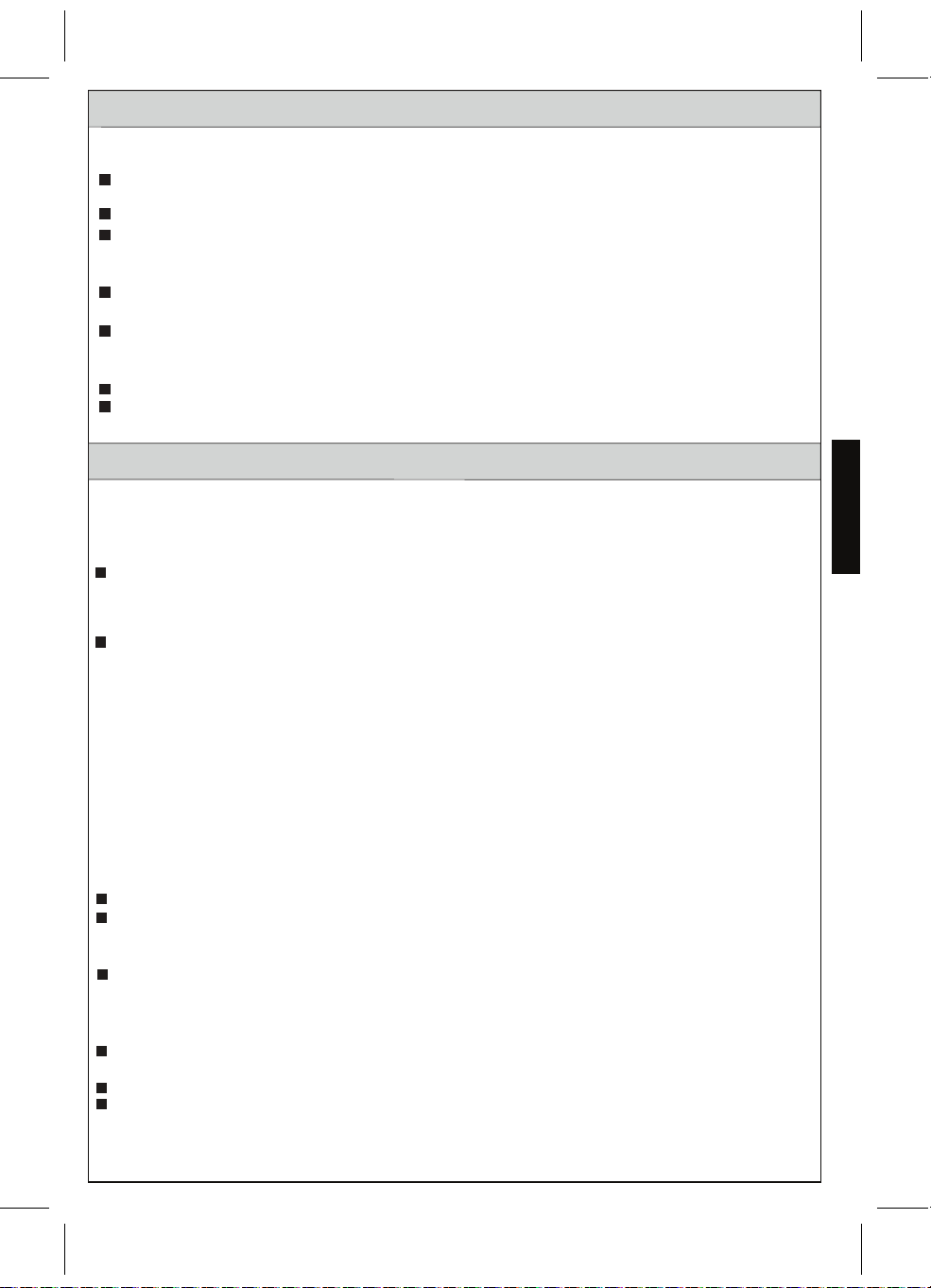
USING THE FLUSH VALVE
Using the Toilet Flush Valve
Infrared Sensor Flushing
Flushing Every 24 hours
ENGLISH
The infrared sensor detects
a user of the toilet.
Using the Urinal Flush Valve
Infrared Sensor
The infrared sensor detects
a user standing within
2 ft (600 mm) of the front of
the urinal.
Common
Manual Flushing Button
When the user stays in place
longer than 6 seconds then
moves away, the controller
sends a signal to the operating
unit to automatically trip the
Flush Valve after 3
seconds delay.
Flushing
When the user stays in place
longer than 6 seconds then
moves away, the controller
sends a signal to the operating
unit to automatically trip
the flush. (No delay)
If toilet is not used for 24 hrs,
the system automatically
flushes as a maintenance
and hygienic precaution.
Flushing Every 12 hours
If urinal is not used for 12 hrs
the system
flushes
and hygienic precaution.
automatically
as a maintenance
Use the manual flush button
for maintenance and/or
emergencies.
11
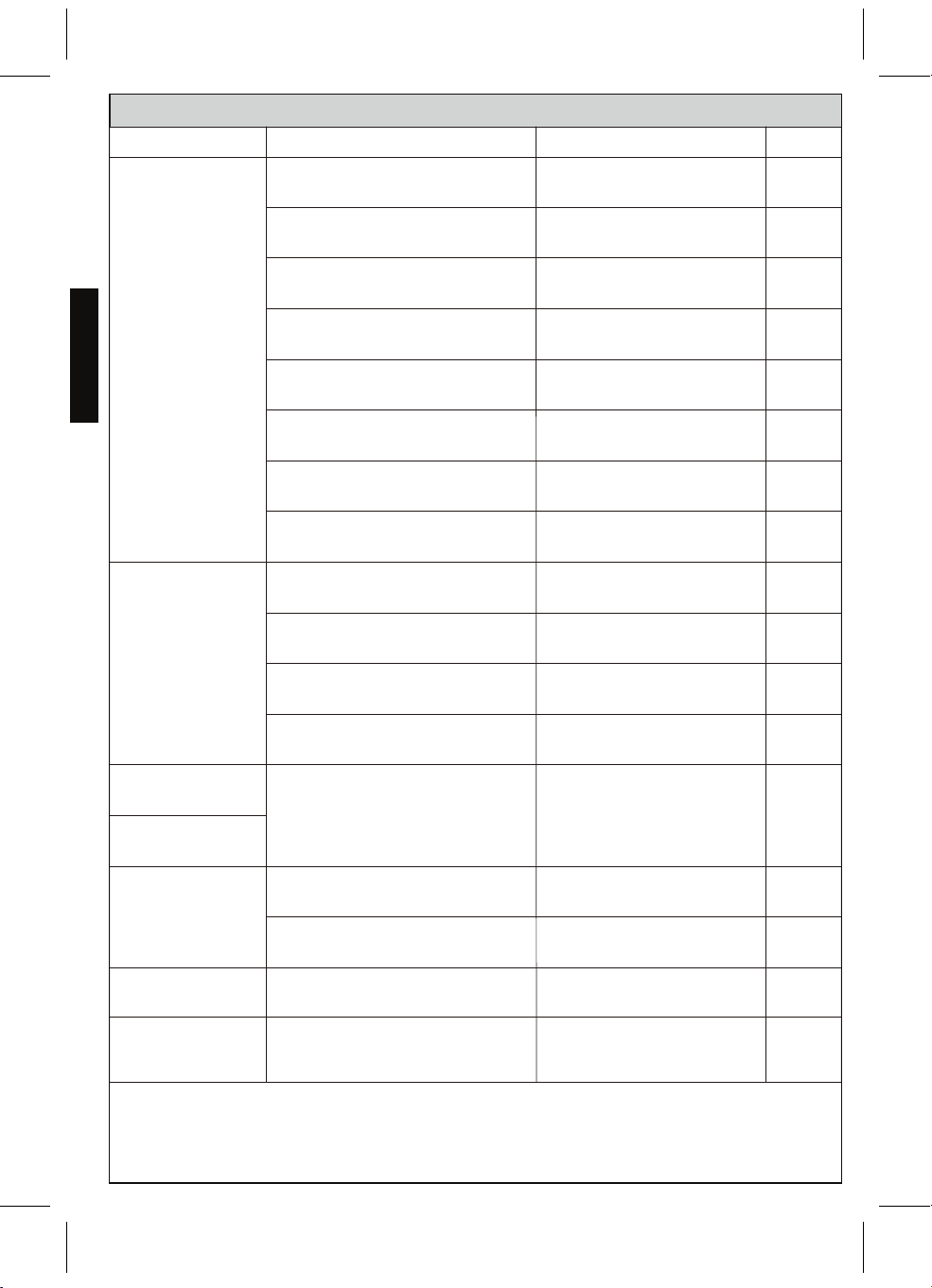
Problem
ENGLISH
No water comes
from the
Flush Valve
Water does not
stop flowing
The discharge
volume is too small
The discharge
volume is too much
The flow rate is too
low
The flow rate is too
high
A red light in the
sensor window blinks
TROUBLESHOOTING
The main valve in water supply
line or the control stop is shut off
One or more cables not
connected
The surface of the glass in front
of the infrared sensor is dirty
The glass is broken
There is a reflective surface in
front of the sensor
The infrared sensor or the
solenoid is out of order
The small holes in the solenoid
diaphragm are clogged
Hydropower generator is clogged
The small hole in the piston is
clogged (not for TEU1UA(R)(X))
The sealing area of the piston is
dirty (not for TEU1UA(R)(X))
The sealing area of the solenoid
diaphragm is dirty
Piston u-packing is damaged
(not for TEU1UA(R)(X))
The screw of the control stop is
not adjusted properly
Water supply pressure is too low
(below rated minimum pressure)
The control stop is not open
enough
The control stop is not adjusted
properly
The battery is weak
Ref.PageSuggested ActionPossible Cause
Open the main valve or the
control stop
Check all cable connections
Clean the surface of the
glass
Contact distributor for
replacement
Remove the reflective
surface in front of sensor
Contact distributor for
replacement
Clean the small hole in the
diaphragm and filter
Service hydropower
generator
Clean the small hole in the
piston
Clean the sealing area of
the piston
Clean the sealing area of
the diaphragm and filter
Inspect & replace if
necessary
Adjust the discharge quantity
by the screw of the control
stop
Consult with a plumbing
contractor
Adjust the control stop
properly
Adjust the control stop
properly
Check voltage with multimeter,
if below 2.6 V, contact TOTO
for replacement battery.
-
-
-
-
15
-
14
-
13
13
14
13
14
-
14
14
14
NOTE: Do not dismantle parts of the Flush Valve which are not specified in the
troubleshooting guide.
If you need further assistance, please call TOTO Technical Support at (888) 295-8134.
12
13
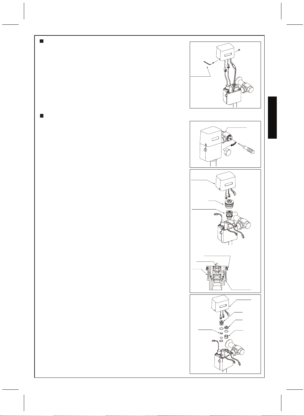
DISASSEMBLY
If the whole valve needs to be removed from the water
supply for servicing, please be aware of the cautions
below:
1. Be careful not to lose or tear the friction washer at the
outlet connection to the vacuum breaker tube nut. To
maintain a proper seal, replace the washer if necessary.
2. When re-installing the valve to the water supply, avoid
pinching the o-ring.
CLEANING PISTON ASSEMBLY AND FILTER
1. Turn the screw of the control stop clockwise to turn off
the water.
Hex wrench
Top cover
Cap
Piston assembly
Control stop
ENGLISH
2. Take out the piston assembly (except for TEU1UA(R)(X))
or take out the filter for TEU1UA(R)(X).
3. Check the small hole in the piston to see if it is clogged
with debris. Insert a small wire to unclog hole if needed.
4. Check the filter to see if it is clogged with debris and
gently brush it clean.
5. Check the sealing area of the piston and clean it if it is
dirty.
6. Check the U-packing for cracks or damage.
Small hole
Filter
Flow
regulator
Piston U-packing
TET1GAR
TET6GAR
TET1UA(R)(X)
TET6UA(R)(X)
TEU1GAR
TET1LA(R)(X)
TET6LA(R)(X)
TEU1LA(R)(X)
Sealing area
Top cover
Cap
Cap
Filter
TEU1UA(R)(X)
CLEANING DIAPHRAGM AND FILTER
1. Turn the screw on the control stop
clockwise to turn off the water.
2. Disconnect the solenoid.
3. Remove the solenoid and take out the
diaphragm. Then check the small holes
ENGLISH
and sealing area.
NOTE: See below for disassembly.
NOTE: Do not stretch or alter the shape of
the spring in the solenoid valve in
any way. It will void the warranty.
CHECKING THE SOLENOID
1. Make sure the batteries are properly placed and cables are connected.
2. With water supply turned off, place your hand in front of the sensor for 6 seconds.
3. Remove and listen for a “click” sound after 3 seconds. This indicates the solenoid
plunger has been activated.
BATTERY REPLACEMENT
A special lithium back-up battery is used. Replace
only with the battery provided by TOTO.
Small holes
Sealing area
O-ring
Cap
Filter
Sensor unit
Solenoid
Spring
Plunger
Diaphragm
If a red light in the sensor window blinks with the
cycle of 4 seconds, it is time to replace the
battery.
1. Remove the old battery.
2. Set the new battery at the proper position.
ADJUSTMENT OF THE FLOW RATE
1. Adjust the flow rate by the turning screw on the control stop.
2. Turn the screw to the right to decrease the flow rate and turn to the left to increase.
Control stop
14
15
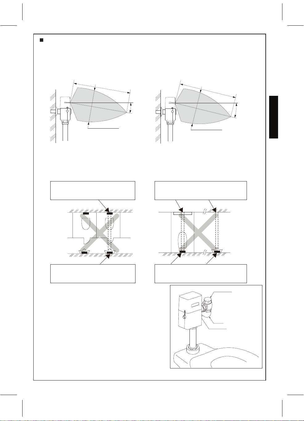
DETECTION RANGE
The detection range of the infrared sensor is set at the factory and does not need
further adjustment.
TET1GAR, TET1LA(R)(X), TET1UA(R)(X)
TEU1GAR, TEU1UA(R)(X)
TEU1LA(R)(X)
TET6LA(R)(X), TET6UA(R)(X)
TET6GAR
33-1/2"
(850mm)
Max 19-11/16”
(Max 500mm)
PRECAUTION
DO NOT place the infrared sensor
of one Flush Valve so that it is in
line with the sensor of another
Flush Valve sensor.
Another infrared sensor.
15°
33-1/2"
(850mm)
20°
Max 21-1/4”
(Max 550mm)
PRECAUTION
DO NOT place the infrared sensor in
front of a mirror, stainless steel wall,
or other highly reflective surface.
Mirror, stainless steel wall or other
highly reflective surface.
ENGLISH
Infrared sensor of the automatic
Flush Valve.
NOTE: In some cases, the valve may not
detect a user if the toilet seat is left
in an upright position. This can be
due to the rough-in dimension or
gap of the open front commercial
seat. Please lower the seat or
arrange with a TOTO or other
plumbing contractor to change the
height of the valve.
The sensor can have trouble
detecting users wearing black
clothes in some conditions.
Infrared sensor of the automatic
Flush Valve.
Control stop
Use chrome plated
elbow to adjust the
height of TOTO
EcoPower Flush
Valve from the
fixture.
Elbow
Wall flange

WARRANTY
1. TOTO warrants its electronic flush valves, faucets and soap dispensers (“Product”) to be free from defects in
materials and workmanship during normal use when properly installed and serviced, for a period of three (3) years
from date of purchase. This limited warranty is extended only to the ORIGINAL PURCHASER of the Product and is
not transferable to any third party, including but not limited to any subsequent purchaser or owner of the Product.
This warranty applies only to TOTO Product purchased and installed in North, Central and South America.
2. TOTO’s obligations under this warranty are limited to repair, replacement or other appropriate adjustment, at
ENGLISH
TOTO’s option, of the Product or parts found to be defective in normal use, provided that such Product was properly
connection with warranty repairs or replacements. TOTO is not responsible for the cost of removal, return and/or
reinstallation of the Product.
3. This warranty does not apply to the following items:
a. Damage or loss sustained in a natural calamity such as fire, earthquake, flood, thunder, electrical storm, etc.
b. Damage or loss resulting from any accident, unreasonable use, misuse, abuse, negligence, or improper
care, cleaning, or maintenance of the Product.
c. Damage or loss resulting from sediments or foreign matter contained in a liquid soap system.
hazardous environment, or improper removal, repair or modification of the Product.
e. Damage or loss resulting from electrical surges or lightning strikes or other acts which are not the fault of
TOTO or which the Product is not specified to tolerate.
f. Damage or loss resulting from normal and customary wear and tear, such as gloss reduction, scratching or
fading over time due to use, cleaning practices or water or atmospheric conditions, including but not limited
to, the use of bleach, alkali, acid cleaners, dry (powder) cleaners or any other abrasive cleaners or the use
of metal or nylon scrubbers.
4. In order for this limited warranty to be valid, proof of purchase is required. TOTO encourages warranty registration
upon purchase to create a record of Product ownership at http://www.totousa.com is required. TOTO encourages
registration upon purchase and failure to register will not diminish you r limited warranty rights.
5. THIS WARRANTY GIVES YOU SPECIFIC LEGAL RIGHTS. YOU MAY HAVE OTHER RIGHTS WHICH VARY
FROM STATE TO STATE, PROVINCE TO PROVINCE OR COUNTRY TO COUNTRY.
6. To obtain warranty repair service under this warranty, you must take the Product or deliver it prepaid to a TOTO
service facility together with proof of purchase (original sales receipt) and a letter stating the problem, or contact
a TOTO distributor or products service contractor, or write directly to TOTO U.S.A., INC., 1155 Southern Road,
Morrow, GA 30260 (888) 295 8134 or (678) 466-1300, if outside the U.S.A. If, because of the size of the Product
or nature of the defect, the Product cannot be returned to TOTO, receipt by TOTO of written notice of the defect
to repair the Product at the purchaser’s location or pay to transport the Product to a service facility.
sa snoitcepsni hcus ekam ot thgir eht sevreser OTOT .snoitcurtsni htiw ecnadrocca ni decivres dna desu ,dellatsni
ni strap ro robal rof egrahc ton lliw OTOT .tcefed eht fo esuac eht enimreted ot redro ni yrassecen eb yam
ro/dna hsrah a ni tcudorP eht fo noitallatsni morf ro noitallatsni reporpmi morf gnitluser ssol ro egamaD .d
esoohc yam OTOT ,esac hcus nI .yreviled etutitsnoc llahs )tpiecer selas lanigiro( esahcrup fo foorp htiw rehtegot
THIS WRITTEN WARRANTY IS THE ONLY WARRANTY MADE BY TOTO. REPAIR, REPLACEMENT OR OTHER APPROPRIATE
ADJUSTMENT AS PROVIDED UNDER THIS WARRANTY SHALL BE THE EXCLUSIVE REMEDY AVAILABLE TO THE ORIGINAL
PURCHASER. TOTO SHALL NOT BE RESPONSIBLE FOR LOSS OF THE PRODUCT OR FOR OTHER INCIDENTAL, SPECIAL
OR CONSEQUENTIAL DAMAGES OR EXPENSES INCURRED BY THE ORIGINAL PURCHASER, OR FOR LABOR OR OTHER
COSTS DUE TO INSTALLATION OR REMOVAL, OR COSTS OF REPAIRS BY OTHERS, OR FOR ANY OTHER EXPENSE NOT
SPECIFICALLY STATED ABOVE. IN NO EVENT WILL TOTO’S RESPONSIBILITY EXCEED THE PURCHASE PRICE OF THE
PRODUCT. EXCEPT TO THE EXTENT PROHIBITED BY APPLICABLE LAW, ANY IMPLIED WARRANTIES, INCLUDING THAT
OF MERCHANTABILITY OR FITNESS FOR USE OR FOR A PARTICULAR PURPOSE, ARE EXPRESSLY DISCLAIMED. SOME
STATES DO NOT ALLOW LIMITATIONS ON HOW LONG AN IMPLIED WARRANTY LASTS, OR THE EXCLUSION OR
LIMITATION OF INCIDENTAL OR CONSEQUENTIAL DAMAGES, SO THE ABOVE LIMITATION AND EXCLUSION MAY NOT
APPLY TO YOU.
16
17
ÍNDICE
¡Gracias por elegir TOTO!......................................................................................................................17
Incluía partes.............................................................................................................................................17
Herramientas que necesita.....................................................................................................................18
Inicialización del producto.......................................................................................................................18
Características................................................................................................................ ................18
Especificaciones........................................................................................................................19
Información técnica.................................................................................................................................20
Advertencias........................................................................................................................................21
Antes de la instalación..............................................................................................................................21
Procedimiento de instalación..................................................................................................................22
Prueba
de funcionamiento......................................................................................................................25
Después de la instalación.........................................................................................................................25
Mantenimiento periódico........................................................................................................................25
Cuidado y limpieza..................................................................................................................................25
Uso del fluxómetro...................................................................................................................................26
Resolución de Problemas........................................................................................................................27
Garantía.........................................................................................................................................31
Bosquejo.................................................................................................................................62
Especificaciones de Agua Reclamada
......................................................................................64
¡GRACIAS POR ELEGIR TOTO!
La misión de TOTO es dar al mundo estilos de vida más saludables, higiénicos y cómodos.
Diseñamos cada producto guiándonos por el principio del equilibrio entre forma y función.
Felicitaciones por su elección.
INCLUÍA PARTES
Asegúrese que todas estas partes estén incluidas en su empacado*:
ESPAÑOL
TEU1UA(R)(X)
Montaje de Cubierta Superior
Fluxómetro del Inodoro
Etiqueta de Aviso
* El producto real puede variar en apariencia dependiendo del modelo.
A excepción de
TEU1UA(R)(X)
Montaje de Cuerpo
de la Válvula
de Respaldo
Para: TEU1UA(X)12, TEU1LA(X)(12,22),TEU1GA(12,22), TET1UA(X)32,
TET1LA(X)32, TET6LA(X)32, TET1GA32, TET6GA32,
Rompedor de Vacío
(con spud junta)
TornillosBatería Paquete
Llave de Paso Kit Adaptador de Soldadura
Llave Allen
TET6UA(X)32
(Escudo, Tubo que Cubre,
Adaptador)
Manual de
instalación y
del propietario
HERRAMIENTAS QUE NECESITA
Llave ajustable
Destornillador (Phillips y Plano)
Llave de tubo
INICIALIZACIÓN DEL PRODUCTO
Gracias por elegir la última innovación en productos EcoPower de bajo consumo de energía.
Tenga en cuenta a continuación la duración del tiempo necesario para inicializar la electrónica.
ESPAÑOL
Tenga en cuenta que tardará al menos 5 minutos después de conectar la batería para que la
electrónica se inialice.
Después de aproximadamente 30 segundos, el LED del sensor comenzará a parpadear en
intervalos de 4 segundos hasta que finalice la inicialización.
Este retraso es una parte normal del inicio
CARACTERÍSTICAS
Completamente Automático e Higiénico
El fluxómetro EcoPower utiliza un sensor infrarrojo para detectar al usuario que utiliza y acciona
el aparato, para proporcionar una descarga automática después de un breve retraso. No se
requiere ninguna operación manual para mejorar la experiencia de uso y la higiene del aparato.
Temporizador de Protección del Sistema
Cuando el dispositivo no se usa durante 24 horas (12 horas para TEU1LA(R)(X) y
TEU1UA(R)(X)) El temporizador de protección ordena al sistema que se descargue para
mantener el sello de la trampa.
Funcionalidad Manual
El fluxómetro EcoPower tiene un botón manual de descarga para el mantenimiento y el uso de
emergencia.
Características Ecológicas
Conserva la Energía
Cada descarga activa un generador de energía hidráulica que genera energía eléctrica para la
siguiente descarga. (Consulte Acerca del Generador de Energía Hidráulica de TOTO, p.20)
Conserva el água
Existen dos funciones que ayudan al fluxómetro EcoPower a conservar el agua:
Control Lógico Difuso
El fluxómetro EcoPower puede detectar con qué frecuencia y durante cuánto tiempo se ha
utilizado el aparato para entregar la cantidad correcta de agua. (Consulte Acerca de Control
Lógico Difuso, p.20)
Antidescarga Consecutiva
El fluxómetro EcoPower ofrece la prevención de descargas consecutivas que ahorran agua.
Después de una descarga, la válvula no se volverá a descargar de manera automática durante
10 segundos para los urinarios y 30 segundos para los inodoros.
Los fluxómetros EcoPower de TOTO están diseñadas para funcionar durante 10 años, en
condiciones normales, sin uso mínimo requerido.
18
Figura
ESPECIFICACIONES
Inodoro Urinario
Número de modelo
Volumen de descarga
Tipo
Control stop inlet
Entrada de
Salida de
Presión de
suministro de
agua
fluxómetro
fluxómetro
Mínimo
(Fluir)
Máximo*
(Estática)
Presión de cierre
Dimensión de
la cubierta
Rango de detección
de frente
Tiempo de detección
TET1GAR
TET6GAR
1.6 G
(6 L)
TET1LAR
TET1LAX
TET6LAR
TET6LAX
1.28 G
(4.8 L)
TET1UAR
TET1UAX
TET6UAR
TET6UAX
1G
(3.8 L)
TEU1GAR
Control lógico
difuso
0.5 G (1.9L)
Típica
TEU1LAR
TEU1LAX
0.5 G (1.9 L)
1.0 G (3.8 L)
Tipo de válvula de descarga Mingitorio de baldeo
1"NPT 3/4"NPT
1-1/4"NPSM
1-1/2"NPSM
15 psi
(103 kPa)
125 psi
(862 kPa)
35 psi
(241 kPa)
125 psi
(862 kPa)
15 psi (103 kPa)
125 psi (862 kPa)
7 psi (48 kPa)
7" (H) x 4-9/16"(W) x 3-3/16"(D)
(178 mm (H) x 115 mm (W) x 81 mm (D))
Dentro de 33-1/2" (850 mm)
6 s
TEU1UAR
TEU1UAX
0.125 G (0.47 L)
ESPAÑOL
Protección del sello
de la trampa
Temperatura ambiente
Temperatura de agua
NOTA:
Consulte al fabricante del aparato para la presión mínima requerida para la válvula. Para el
Descarga automática cada
24 horas de no utilización
32-104˚F (0-40˚C)
34-104˚F (1-40˚C)
Descarga automática cada
12 horas de no utilización
rango de detección funcione correctamente, TET6LA(R)(X), TET6UA(R)(X) y TET6GAR requeiren
igualador de
presión 24" o más largos.
* No se recomiendan las presiones de agua de más de 80 psi para la mayoría de los accesorios de plomería.
19
Controlador
INFORMACIÓN TÉCNICA
Acerca del Generador de Energía Hidráulica
El flujo de agua hace que la turbina gire en el generador de energía. Este proceso genera energía
eléctrica y permite que funcione el fluxómetro automática. Ver ilustración 1 a continuación.
Sensor
Sensor
Controlador
Pistón
Fluxómetro
Línea de suministro de agua
Resorte
Cubierta
Fluxómetro
Línea de suministro de agua
Resorte
Turbina
Turbina
Cubierta
TET1GAR
El Fluxómetro
TET6GAR
TEU1GAR
TET1LA(R)(X)
TET6LA(R)(X)
TEU1LA(R)(X)
TET6UA(R)(X)
TET1UA(R)(X)
3)
Automática utiliza la
energía cargada.
La energía eléctrica se
2)
almacena en un
condensador.
Una turbina gira para
1)
generar energía
eléctrica.
TEU1UA(R)(X)
ESPAÑOL
El Fluxómetro
3)
Automática utiliza la
energía cargada.
La energía eléctrica se
2)
almacena en un
condensador.
Una turbina gira para
1)
generar energía
eléctrica.
ill. 1 Generador de Energía Hidráulica
Acerca de Control Lógico Difuso (TEU1GAR sólo)
La función Control Lógico Difuso ajusta de manera automática la descarga de agua de
acuerdo con la frecuencia y la duración de uso (ver ilustración 2 y ilustración 3).
El sistema Control
Lógico Difuso del
sistema determina la
frecuencia de uso por
el tiempo de
inactividad del urinario
y hace que el
fluxómetro suelte agua
en un patrón óptimo de
descarga.
Tiempos Cortos de Inactividad Tiempos Largos de Inactividad
Típica
Menos
Menos Menos Menos Menos
Para los tiempos cortos de inactividad, el sistema asume
el uso frecuente del urinario y el fluxómetro suelta
menos agua.
Ejemplos de uso frecuente sería durante una pausa para
almorzar o un intermedio en una sala de cine.
Menos
Para tiempos largos de inactividad, el
sistema asume un uso poco frecuente, y
hace que el fluxómetro entregue una
cantidad típica de agua para una
limpieza a fondo.
Ejemplos de uso poco frecuente sería
después de las horas en la oficina o un día
lento en el parque day at the park.
Típica
ill. 2 Frecuencia de Uso
El sistema Control
Lógico Difuso predice la
cantidad de agua de
descarga necesaria, en
base a la duración de
uso del usuario.
Largo Período de Uso Corto Período de Uso
Típica
Un largo período de uso indica
que puede haber más para
limpiar, lo cual requiere que el
fluxómetro entregue una cantidad
típica de agua de descarga para
una limpieza a fondo.
Un corto período de uso
Menos
indica que puede haber
menos que limpiar, lo que
requiere que el fluxómetro
suelte menos agua para la
limpieza.
ill. 3 Duración de Uso
20
ADVERTENCIAS
Lea y cumpla estas instrucciones. El no hacerlo podría dar lugar a lesiones personales o
daños materiales.
Nunca salpique agua en el controlador. El fluxómetro EcoPower es un aparato eléctrico.
Riesgo de mal funcionamiento del producto.
No golpee ni patee el fluxómetro EcoPower. Riesgo de mal funcionamiento o fuga de agua.
No utilice el fluxómetro EcoPower a temperaturas superiores a las permitidas por los
códigos locales o las especificaciones del producto. Riesgo de mal funcionamiento del
producto.
No coloque el fluxómetro EcoPower en una habitación con alta humedad, como el área de la
ducha o en la sauna. Riesgo de mal funcionamiento del producto.
Nunca intente desmontar, volver a montar, reparar o modificar el fluxómetro EcoPower a
menos que usted sea un profesional. Riesgo de mal funcionamiento del producto y
descargas eléctricas.
No utilice el interruptor de vacío o la llave de paso con válvula de descarga de agua saneada.
No utilice sellantes de tubería o productos a base de petróleo, hacerlo podría dañar el
producto y causar daños por agua.
ANTES DE LA INSTALACIÓN
Importante: La instalación de la plomería debe hacerse de acuerdo con los códigos y
reglamentos aplicables. Las líneas de suministro de agua deben dimensionarse para
proporcionar un volumen adecuado de agua para cada aparato. Descargue todas las líneas
de agua antes de utilizarlas.
Los fluxómetros de inodoro y urinario no son intercambiables, compruebe el número de
modelo en la etiqueta para asegurarse de que tiene el tipo correcto. Los números de
modelo del fluxómetro del inodoro comienzan con 'TET' y los modelos del fluxómetro
urinario empiezan con 'TEU'.
Antes de instalar su fluxómetro, instale los elementos que se enumeran a continuación:
Accesorio Inodoro/Accesorio Urinario
Línea de drenaje
Línea de suministro de agua
La tubería de suministro de estos dispositivos debe estar anclada firmemente a la estructura
del edificio para evitar que el dispositivo instalado se mueva durante el uso. Tenga cuidado al
instalar el dispositivo para evitar estropear la superficie expuesta. Importante: Limpie todo el aire
de las líneas de suministro antes de conectar la válvula de descarga al recipiente. El aire atrapado
en las líneas de suministro puede romper la china.
A excepción de TET6GAR, TET6UA(R)(X) y TET6LA(R)(X), instale el
paso no sea inferior a 11-1/8" (282mm) por encima de la parte superior de la taza/urinario. Para
TET6GAR, TET6UA(R)(X) y TET6LA(R)(X), instale el
encuentre a 27" (685,8 mm) por encima de la taza/urinario.Ver los códigos locales para obtener
información acerca de los requisitos especiales.
Tenga cuidado de no dañar la superficie del sensor infrarrojo.
Para el fluxómetro del Inodoro:
El fluxómetro del inodoro puede no funcionar si el asiento y/o la tapa del inodoro
se dejan en posición vertical, ya que puede bloquear el sensor.
Para el fluxómetro del Urinario:
El fluxómetro del urinario está diseñada para un rendimiento óptimo con urinarios
de lavado para un rendimiento óptimo, pero se puede sustituir un urinario de chorro. No se
recomiendan los urinarios Blowout.
fluxómetro
Para la válvula de descarga de agua saneada:
Utilice únicamente el interruptor de vacío y la llave angular de agua saneada.
Ver rango de detección del sensor infrarrojo en p. 30.
Para evitar el mal funcionamiento del
objeto dentro del rango de detección del sensor. No instale el fluxómetro donde el
sensor esté al frente de un espejo, una pared de acero inoxidable, otras superficies altamente
reflectantes u otro sensor infrarrojo.
fluxômeter
, no instale un pasamanos o cualquier otro
21
fluxómetro
de modo que la llave de paso se
de modo que la llave de
ESPAÑOL
 Loading...