

Page 1
NEOREST® Installation Instructions <Bowl>
The installation of the toilet bowl for the NEOREST® differs from installation
of conventional toilet bowls. Be sure to read the following installation
instructions and install the product only as described in this manual.
✲ Before installation, confirm that the parts listed below are included in the
kit.
Before installing the NEOREST
®
, be sure to read the safety instructions in
"Always Follow This Precaution" and install the product only as described
in the instructions. Precautionary symbols are used in these instructions to
ensure safe and proper installation of the product and to prevent injury to
the end-user and damage to personal property. The definitions of these
precautionary symbols are as follows.
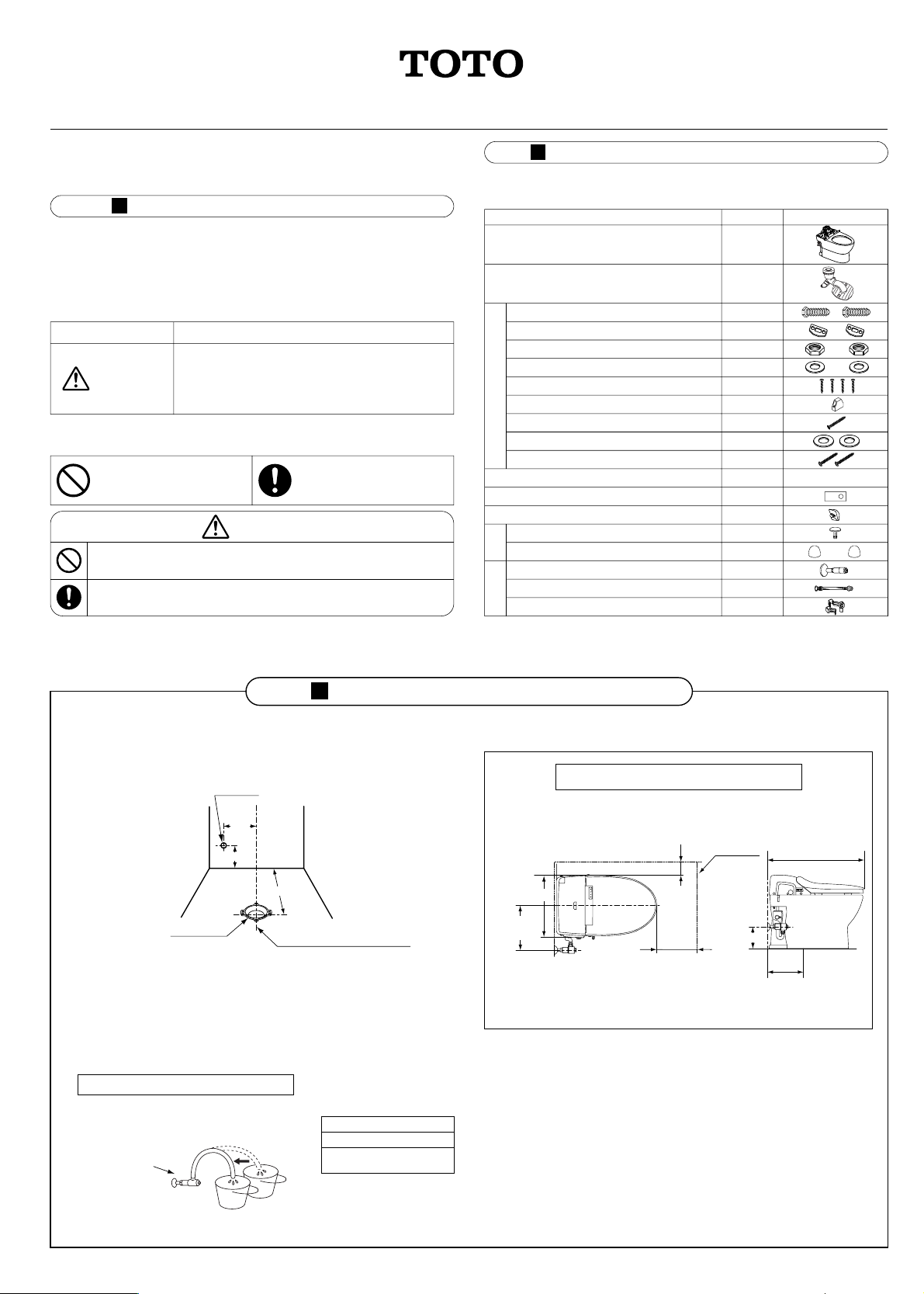
■ Confirm that there is enough floor space to install the toilet unit and
that the bathroom door will open/close without obstruction.
■ Confirm that the position of the drain hole and pipes are properly lined
up as designated in the drawing.
■ Water Pressure.
The NEOREST
®
is designed to operate under a minimum working
pressure of 10 psi flowing. It should be noted that the standard range of
working pressure allowed by model codes is 20 to 80 psi static.*
It is necessary to install the water shutoff valve (angle stop) provided
with the NEOREST
®
. This will assure the proper flow ratio is achieved
and allow for optimum performance of the unit.
*See warranty for details.
There are two types of precautionary symbols. The symbols and definitions
appear below.
When this symbol appears, precaution should be
taken to ensure proper and safe use of the
product. Ignoring this precaution could result in
injury or damage to personal property.
This symbol indicates a
prohibited use of the
product.
Avoid direct impact to the ceramic components as this will break the
ceramic and could result in injury or property damage due to water leakage.
Always use the provided or designated parts for the installation process.
Always Follow This Precaution
Symbol Definition
WARNING
This symbol means "Always
Follow This Precaution".
WARNING
Parts Included in the Installation Kit
Part Name
Toilet 1
1
Outlet connection
(with rubber joint)
Hex bolts
Mounting plates
Nuts
Washers (for outlet connection)
Self tapping screws (for outlet connection)
Mounting block
Pan head screw
Washers (for mounting block)
Self tapping screws (for mounting block)
Screw cap (front)
Decorative caps (back)
Water shutoff valve
Water supply hose (with gasket)
Connecting hose fastener
Installation manual
Installation template
Water diverter cover (with small screw)
2
2
2
2
4
1
1
2
2
1
1
1
1
2
1
1
1
DrawingQuantity
Metal Fittings
Decorator
Caps
Water Supply
Connectors
Before Installing the NEOREST
®
How to check the water pressure:
If a pressure gauge is unavailable, the fill
method may be used as follows.
The following water volumes will ensure
sufficient water pressure.
Product Diagram
NEOREST® water
shutoff valve fully
open condition.
Allow the water to flow into the bucket for
10 seconds and measure the water volume.
Prepare two buckets to
hold the water.
Installation Position
Water volume (for 10 sec)
1.5 Gallons (5.5L) or more
NEOREST
®
water supply valve
fully open condition
0GU9102
H06779R
2006.2
1
2
3
®
15
7
/
8”(404mm)
Bathroom
Door
Drain pipe position
(Measuring Procedure)
This manual
Line designating the center of the
toilet bowl
Closet flange
(Not included)
Drain R1/2
11
3
/
4”
(300mm)
5
7
/
8
”
(150mm)
12” (305mm)
5
7
/
8” (150mm)
at least 15
3
/
4” (400mm)
11
3
/
4”
(300mm)
26
1
/
4 ” (667mm)
5
7
/
8” (150mm)
12”
(305mm)
Washlet unit water
supply connector
Washlet unit water
supply connector
Page 2

Parts and Installation instructions
Installation Procedures
1 Installing the water shutoff valve
① Before installing the water shutoff valve, be
sure to remove any dirt or sand that may
have become lodged inside the valve.
② Wrap the sealing tape around the fitting on
the water supply pipe of the water shutoff
valve.
③ Please make sure that the water supply
from the water shutoff valve faces
downward at a 60° angle and toward the
side of the toilet.
2
Positioning the installation holes with the template
① Align the template with the centerline of the drain pipe on the floor.
② Mark the installation position for the mounting block and the outlet
connection.
Installing in the wrong direction
could lead to twisting of the
hose, causing flushing
problems or leaks.
5
Flush valve connector
Toilet flushing valve
Manual flush handle
Decorative cap (back)
Nut
Washer (for outlet connection)
Toilet
Pan head screw
Screw cap (front)
Self tapping screw (for mounting block)
(Not included)
Washer (for mounting block)
Mounting block
Wax ring
(Not included)
(Not included)
Water shutoff valve
Mounting
plate
Water supply hose
Hex
bolt
Water diverter cover
Self tapping screw (for outlet connection)
Point ③
Attach the water diverter cover after the
Washlet has been installed. s See step 6
T bolt
Centerline of drain pipe
11
3
/
4” (300mm)
60°
5
7
/
8”
(150mm)
Installation hole of
mounting block
Drain pipe
Outlet connection
installation hole
Template
Point ①
Determine the proper positioning for
the mounting block using the
template. s See step
2
Point ②
Secure the rear of the toilet first.
Do not overtighten and break the porcelain.
s See step
4
4
Water supply inlet
Remove dirt
and sand
Water supply
pipe
Water shutoff
valve
Sealing tape
Water shutoff valve
WARNING
Depending on the time of manufacture, there may
or may not be a fastener guide.
Without a fastener guide With a fastener guide
Washlet unit water
supply connector
Water
diverter
Inlet water
supply hose
Inlet water
supply hose
Fastener
guide
Water
diverter
Washlet unit water
supply connector
Washlet unit water
supply connector
Washlet unit water
supply connector
Page 3

3 Fixing the outlet connection and the mounting blocks
① The hex bolt should be placed in the hexagon shaped hole. The mounting plate should be placed over the bolt and screwed into the floor with self
tapping screws.
② To attach the front part, mount to the floor flange withTbolts, washers and nuts (Not included).
③ The front mounting block is then attached with self-tapping screws.
4 Toilet Installation
① Remove debris from around the periphery of the rubber joint on the outlet connection and the drain horn underneath the toilet before inserting the
drain horn into the outlet connection.
② Affix the installation holes (two holes) at the back of the toilet to the outlet connection with the washers and nuts and put the decorative caps on.
③ Insert the pan head screw into the installation hole at the front of the toilet and secure the toilet to the mounting block. Press the screw cap into the
screw head.
Please place the head of the hex bolt securely in the
hexagonal hole in the outlet connection.
If it isn't placed securely in the hole, the toilet could wobble.
Always
Do
Please be sure to secure the
rear of the toilet first. If the
front end is secured first, the
toilet could slide rearward,
resulting in leaks.
Self tapping screws (for outlet connection)
Side-securing point of outlet connection
Floor flange mounting point outlet connection
Self tapping screw (for mounting block)
Washer (for mounting block)
Mounting block
Pre-installed floor flange
Mounting plate
Hex bolt
Outlet connection
Remove debris
Rubber joint
Toilet drain horn
Decorative cap (back)
Nut
Washer (for outlet connection)
Pan head screw
Screw cap (front)
Toilet
Toilet drain horn
Installation hole
Mounting block
Procedure ①
Please tighten all screws and bolts securely.
Please be careful not to overtighten the nuts
and crack the toilet.
Procedure ②
Please be careful not to over-tighten
the pan head screw and crack the
toilet.
WARNING
WARNING
Page 4

For Better Results
The manufacturer recommends that silicone caulking be applied around the bottom of the toilet bowl base to prevent
water and urine from seeping under the flooring material, resulting in a stained floor.
Silicone caulking
Interior wall of the toilet bowl
Exterior surface of the toilet bowl
6
Installation of the water supply hose and water diverter cover
5
Installing the Washlet units
Refer to the installation instructions included in the packaging for the Washlet unit.
When checking the water flow the first time, if you
are making the check with the "manual flush handle",
be sure to turn it toward the front (toward the rim).
If you turn it "towards the rear," there is a
chance that air in the pipes will cause the water to
continue flowing.
Round head
screw (small)
Water diverter cover
Gasket
Water shutoff valve
Diverter
Connecting hose fastener
Water supply hose
Fastener Guide
Depending on the time of
manufacture, there may or
may not be a fastener guide.
Washlet unit connecting hose
Connecting hose fastener
Toward the
front
Manual Flush
Handle
①
Put the gasket in the closed end nut and secure to the
water shutoff valve.
②
Connect the connecting hose in the Washlet unit.
For more details, please see the installation manual
packed with the Washlet unit.
1
WARNING
2
Required
③
Run through a trial operation and check for leaks.
④
Attach the water diverter cover.
 Loading...