

Toto CST423SF, CST424SFG, CST743S, CST744S, CST424SF Installation Manual
...
Warranty Registration and Inquiry
For product warranty registration, TOTO U.S.A. Inc. recommends online warranty registration. Please visit
our web site http://www.totousa.com. If you have questions regarding warranty policy or coverage, please contact TOTO U.S.A. Inc., Customer Service Department, 1155 Southern Road, Morrow, GA 30260
(888) 295-8134 or (678) 466-1300 when calling from outside of U.S.A.
Installation Manual
Manual de Instrucciones
Manuel D’Installation
CST423SF
CST424SF(G)
CST743S
CST744S(G)
CST744SL
CST744SF.10
CST754SF(N)
CST784SF
MS756204SF
3
ENGLISH
TABLE OF CONTENTS
THANKS FOR CHOOSING TOTO!
The mission of TOTO is to provide the world with healthy, hygienic and more
comfortable lifestyles. We design every product with the balance of form and function
as a guiding principle. Congratulations on your choice.
Thanks for Choosing TOTO®! ...........................................................................................3
Before Installation ...............................................................................................................3
Common Tools Needed ....................................................................................................3
Included Parts ..................................................................................................................... 3
Before Installation ...............................................................................................................4
Installation Procedure .....................................................................................................4-6
Toilet Tank Fill Valve Instructions ....................................................................................6-7
Care and Cleaning ..............................................................................................................7
Warranty ..............................................................................................................................8
Rough-In Dimensions ...................................................................................................... 21
Replacement Parts ............................................................................................................22
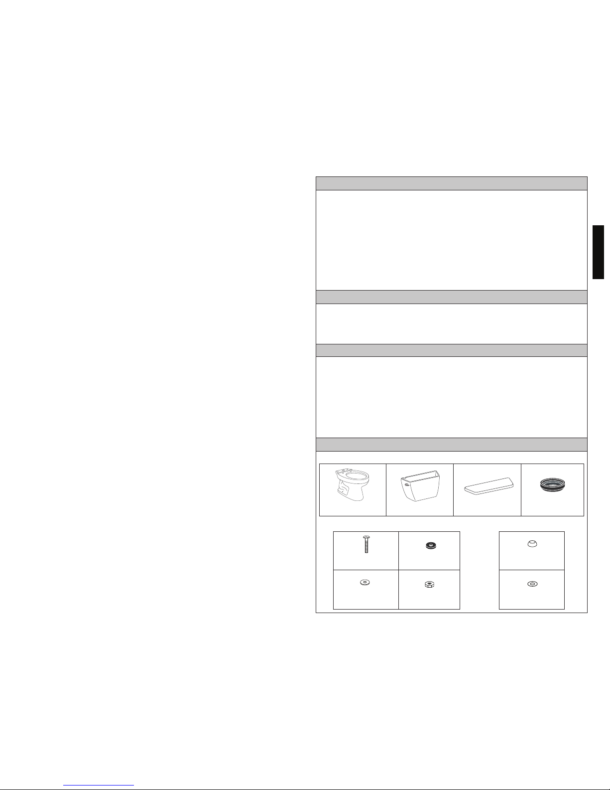
Check to make sure you have all these parts from the package:
COMMON TOOLS NEEDED
INCLUDED PARTS
• 10” adjustable wrench
• Hacksaw
• Carpenter’s Level
MATERIALS REQUIRED:
• Flexible Supply Tube / Connector
• Supply Stop Valve
• Tape Measure
• Pliers
• Screwdriver
• Putty Knife
Tank to Bowl Hardware:
China Bowl
China Tank
Bolts
(2 pieces)
China Tank Lid Tank to Bowl Gasket
Rubber Washers
(2 pieces)
Metal Washers
(4 pieces)
Nuts
(4 pieces)
Flange Caps (for the Bowl):
Plastic Caps
(2 pieces)
Base Caps
(2 pieces)
• Mounting (T) Bolts & Nuts (2pc)
• Wax Ring / Seal
4
ENGLISH
5
ENGLISH
C
U
T
A
W
A
Y
V
I
E
W
BEFORE INSTALLATION
Read these instructions thoroughly before beginning work.
Please leave these instructions for customers. These instructions contain mainte-
nance and warranty information.
If necessary, remove the existing toilet.
INSTALLATION PROCEDURE
In order for your new TOTO® toilet to fit correctly, the distance between the
finished wall to the center of the closet flange must be at least 10 to 12 inches. This
measurement is called the Rough-In.
Supply
Valve
Finished Wall
"RI"
C/L
Closet
Flange
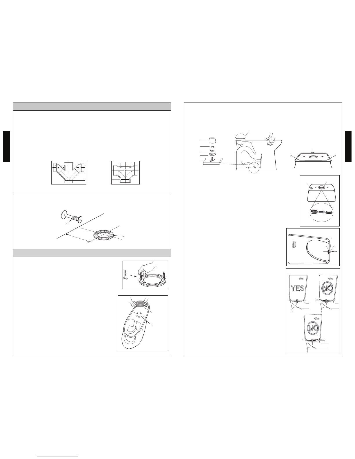
1) Clean any debris out of the closet flange and then
install new mounting bolts (not supplied) into the
slots of the closet flange (see Ill. 1). The head of the
bolt should be inserted into the slot with its threads
facing upward.
2) Carefully turn the toilet upside down onto some
padding. Firmly press a new bowl wax ring (not
supplied) onto the circular recess around the toilet
bowl’s horn (see Ill. 2). Turn the toilet upright and
gently lower into position over the closet flange.
With toilet properly aligned, press firmly on both
sides of toilet rim to set the bowl wax ring.
C AUTION: Do not move the bowl after the bowl
wax ring is set. Thread nuts and tighten evenly
until bowl is snug to closet flange. Install the bolt
caps.
C AUTION: Do not over-tighten the nuts as damage
to the china bowl may result.
Ill. 1
IMPORTANT!
Due to the powerful performance of our Cyclone, G-Max, E-Max and Power Gravity
flushing systems, they are not specified for back-to-back installations. The only
means of installing these toilets in a back-to-back situation is when the toilet drain
connections incorporate a WYE fitting. Please contact your builder or contractor prior
to this installation.
Double Combination WYE / 1/8 Bend
YES
Double Sanitary Tee / Sanitary Cross
NO
Installation Procedures (continued)
4) Place the tank upside down onto some
padding. Inspect the smaller fill valve nut
and larger flush valve nut for a secure connection.
Try to tighten the nuts with your hands see
Ill. 3). If loose, tighten the nut hand tight
and an additional 1/4 turn for the smaller fill
valve nut and an additional 1/2 turn for the
larger flush valve nut.
Place the tank-to-bowl gasket onto the
flush valve nut. While pressing down,
spread the gasket over the nut until the
gasket touches the bottom of the tank. A
slight gap between the tank bottom and
the gasket is allowable.
5) Lay the tank down on its back. Place a rubber washer onto a brass bolt. Reach inside
the tank and position the bolt through one
of the holes in the bottom of the tank (see
Ill. 4).
On the outside of the tank, place a metal
washer and nut onto the bolt. Hold the bolt
centered in the hole and tighten the nut
finger tight. Turn the nut an additional 1/2
turn with a wrench. Repeat this process for
the remaining hole in the tank.
6) Pick up the tank and carefully guide the
brass bolts to align the tank with the bowl.
Attach a metal washer and nut to each bolt.
Tighten the nuts finger tight and inspect
that the tank is level (see Ill. 5). Once level,
tighten the bolts equally until the tank
makes THREE POINTS OF CONTACT with
the bowl.
Ill. 3
Fill Valve Nut
Bolt
Ill. 4
Nut
Rubber Washer
Wax Ring
Horn
Ill. 2
N OTE: The toilet bowl has three points of contact, which will actually contact the bottom of the
toilet tank when properly installed. The location of these points can be seen on the bowl at the
tank receiving area. The three points are front left (1), front right (2), and back center (3). Recall
these three points during the Toilet Tank installation.
Three Points of Contact
Bolt Cap
Nut *
Washer *
Base Cap
Bowl Base
1
2
3
Flush Valve
Nut
Metal Washer
1 & 2
1 & 2
3
3
NO
1 & 2 GAP
NOYES
3 GAP
Tank to Bowl Gasket
Ill. 5

6
ENGLISH
7
ENGLISH
Plastic Bolt
Cap
Seat Hinge
Plastic
Nut
Bowl
Seat Stopper
4
5
6
2
3
1 - Cap
2 - Plastic Bolt
3 - Seat Hinge
4 - Seat Stopper
5 - Toilet Bowl
6 - Plastic Nut
1
Mounting Hardware
7/8” BALLCOCK
THREAD
HAND TIGHTEN
1/4 TURN ONLY
Installation Procedures (continued)
6) Flush the water supply line for a few seconds to
remove any debris that may enter the new fill valve.
(For new home constructions and/or additions, flush
the water supply line for more than a minute to help
remove any residual PVC adhesives, solder flux, and/or
pipe sealants that were used for the new plumbing.)
Connect the water supply line to the fill valve threads
as seen at the bottom of toilet tank (see Ill. 5). Tighten
this connection finger tight and then an additional 1/4
turn by hand. AVOID using a wrench to tighten the
connection as you may damage the plastic threads
and/or cause the fill valve to rotate inside the tank.
Water Supply Line Pressure should be 20 to 80 psi
Static.
N OTE: NO BALLCOCK / FILL VALVE ADJUSTMENTS
NEEDED. Water will automatically stop at the proper
level. Flush the toilet several times. Check the flapper valve for proper operation. Make sure that the
chain is not tangled and the flapper arm is in its
proper position.
Ill. 6
TOILET TANK FILL VALVE INSTRUCTIONS
Replacement Procedure
1) Shut off the water supply to the toilet.
2) Flush toilet and remove remaining water from tank with a sponge.
3) Remove the water supply connection at the fill valve.
4) Remove old fill valve and use damp sponge to clean hole in tank.
5) Place new fill valve inside tank hole.
6) Thread mounting nut onto fill valve shank and tighten the nut.
N OTE: Do not over-tighten. Be sure to install fill valve in a position that does not
interfere with the trip lever operation.
Ill. 5
Water Level Adjustment
Depending on the manufacturing plant, you may have one of two of the following fill
valves:
Type A Type B
Water Level
For Type A Fill Valve:
Refer to the water level (WL) setting marked
on the inner wall of the tank. Allow the water to fill the tank. Turn the adjustment screw
clockwise in the (+) direction to increase the
water level height (see Illustration 1). Turn
the adjustment screw counter-clockwise in
the (-) direction to decrease the water level
height. Flush the toilet to verify the correct
water level. Adjust as necessary.
For Type B Fill Valve:
There are no water level adjustments. The
fill valve has been preset at the factory.
Top of
Overflow
Tube
Water
Level
Ill. 1
Replacement Procedure (continued)
7) Connect water supply to fill valve shank and hand-tighten only.
NO TE: Do not overtighten. These are plastic parts. Never use pipe dope on any
water supply connection.
8) Attach refill tube to fill valve nipple and clip other end of refill tube to the overflow
pipe.
9) Turn water supply ON and check for leaks outside the tank.
NO TE: As water fills the tank, water is also directed into the overflow tube via the
refill tube. This additional flow of water is critical to refilling your toilet’s bowl.
Once the water stops filling the tank, some residual drops of water may drip
from the fill valve. This is NORMAL as these drops will subside.
WARNING!
DO NOT USE IN-TANK BOWLCLEANERS.
The use of high concentration of chlorine or chlorine-related products can seriously
damage fittings in the tank. This damage can cause leakage and property damage.
TOTO® shall not be responsible or liable for any tank fitting failure or damage caused
by the use of in-tank bowl cleaners.
CARE AND CLEANING
7) Install the toilet tank lid onto the toilet tank
top.
8) Install the toilet seat onto the toilet bowl using
the mounting hardware in the toilet seat box
(see Ill. 6). Place seat onto bowl and rotate the
hinge down. Position seat stoppers under the
seat hinge.
Insert bolt into seat hinge and through the
toilet bowl. Install plastic nut onto bolt from
underneath. Tighten the bolt securely. Install
the seat bolt caps.
N OTE: Tighten the seat bolt until the hinge
is secure. The seat and lid will have slight
side to side movement which is normal. This
freedom of movement allows the seat to
SoftClose® without binding.
 Loading...