

Toto LFC991GQ01 Installation Manual
0GU3018-2
2009.4
Neorest Counter Lavatory with Automatic Faucet
Warranty Registration and Inquiry
For product warranty registration, TOTO U.S.A. Inc. recommends online Warranty Registration. Please visit our web site http://www.totousa.com. If you have questions regarding warranty policy
or coverage, please contact TOTO U.S.A. Inc., Customer Service Department, 1155 Southern Road, Morrow, GA 30260 (888) 295-8134 or (678) 466-1300 when calling from outside of U.S.A.
For best results, be sure to follow the installation instructions and use the product only as described in the manual.
Important Safeguards
(For your safety, please follow the instructions below.)
Read the “Important Safeguards” section thoroughly before installing the product.
● The following symbols indicate safe and proper use
of the product. Failure to observe them may result
in injury or property damage.
The symbols and their meanings are as follows:
Sign
Warning
Caution
Ignoring these symbols may result in
serious personal injury.
Ignoring this symbol may result in injury
or property damage.
Meaning
Warning
Do not use an unstable wall outlet
May cause fire or electric shock.
● The following table demonstrates
the use of safety symbols in this
manual.
Do not disassemble
Absolutely “Do Not”.
Do not touch.
Mandatory!
Do Not
No water
No impact
Do not
disassemble
Do not overload the wall outlet or the wiring facilities
Otherwise,it will result in fire due to heat.
Do not reverse the HOT/COLD water supply.
Burns may result from confusing hot water with cold water.
Do not place the product in a room with high
humidity such as shower room or sauna.
May cause product malfunction or electric shock.
Do not strike or kick the product.
May cause damage or water leakage.
Never attempt to disassemble, reassemble, repair
or modify the product, unless you are an electrician
or qualified service person.
May results in property damage and/or personal injury
Do not unplug with a wet hand
May cause electric shock.
Warning
C
Hot side
Cold side
H
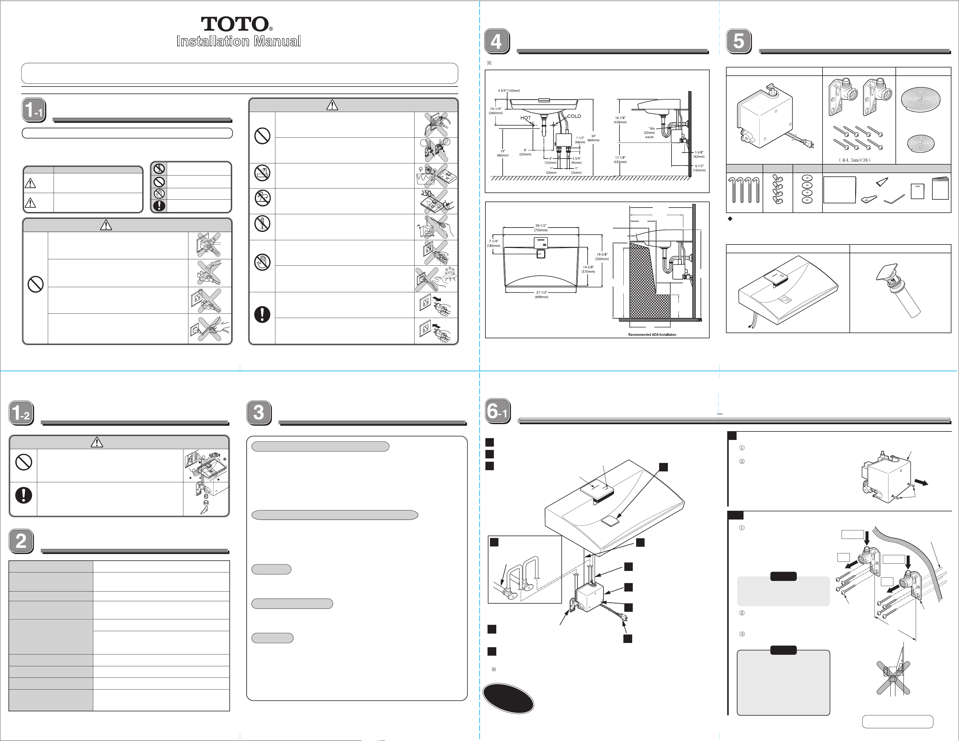
Set-Up Drawing
Some models may have different components as illustrated below.
1-1/4
8”
(203mm)
2-3/4”
(70mm)
11”
(279mm)
26-1/4”
(667mm)
22-3/8”
(568mm)
Installation
Some models may have different components as illustrated below.
Controller
Hook bolts Wing nuts
(4 pcs) (4 pcs) (4 pcs)
Washers
Necessary tools
Adjustable Wrench, Screw Drivers, Drill, Jig Saw, Wrench and Cutters
Lavatory, Automatic faucet and drain
Lavatory with Automatic Faucet
Water inlet bracket Packing material
Water supply bracket (2 pcs)
Tapping screw s (8 pcs)
Others
caulking
template
strainer tool Allen wrench
Installation
Manual Set
Drain
(Large)
(Small)
(1 of each)
Operation
Manual
Do not wet the electric plug or controller
May cause fire or electric shock.
Do Not
Do Not
Mandatory
Only the designated power supply (100-120 V AC,
50-60 Hz ) can be used.
If a port or AC power supply other than the designated is used,
it will result in fire or failure.
Do not handle the power cord violently by folding
it or pressing on it with heavy load
May cause fire or electric shock.
Do not install outdoor or where temperature is likely
to fall below freezing point.
If parts are damaged, property damage may occur due to leakage.
Always close the stop valves before cleaning the
strainer.
Hot or cold water may flow out and cause personal
injury or property damage.
Specification
Model #
Duration of water supply
Power supply
Detection range from
sensor unit
Water supply pressure
Water supply connetion
Ambient temperature
Humidity
Discharge Quantity
Other than the
designated port
or power
supply
Caution
LFC991G, Complete Set
Hand sensor: 60 seconds
Start/Stop Switch on: Continual water Supply
100-120 V AC 50-60HZ
Hand Sensor: within 10 inches (250 mm)
Body Sensor: within 3 feet ( 900 mm)
Lower limit: 15PSI(100kPa) (when flowing)
Upper limit: 125PSI (862kPa)
Check local building codes for maximum water pressure
allowed.
1/2” NPSM
32°F - 104°F (0~40ºC)
Maximum 90%RH
1.7Gal./Cycle (6.5 L/Cycle)
(with built-in regulating valve)
Do not
touch
Mandatory
Do not touch the power plug if there is lightning
May cause electric shock.
Hold the plug body to pull the plug out of the outlet. If
pulled by the cord, it could damage the plug or cord and
could result in fire or electric shock.
Confirm that the power plug is pushed in all the way.
TOTO recommends that the AC adapter be
connected to a GFCI-protected outlet.
May cause fire or electric shock.
Before installation
1. Confirm cold /hot water pressure
● Confirm the cold water pressure is equal to or higher than that of the hot water
If water pressure is higher than 125PSI (862kPa), use a pressure-reducing
valve to reduce it to between 20 and 80 PSI (138 and 551 kPa).
●The optimal pressure ranges is 15PSI to 125PSI (100kPa to 862kPa)
Confirm that the water supply pressure is within this range.
2. Confirm the temperature of hot water supply
● Do not use steam as hot water supply.
● Make sure that the temperature range of hot water supply side is 140 to
185ºF
This is not mandatory for the lower limit but is recommended.
● The auto faucet does not discharge hot water exceeding 122ºF (50°C) .
3. Piping
● Flush all water lines prior to installation.
4. Counter thickness
● The thickness of the counter should be made in the range of 3/8 to 1-3/8
inches (10-35mm).
5. Others
● Special cares should be taken not to damage or scratch the sensor surface.
● You should prepare the stop valve, flexible hose and steel pipe.
● When using the inverter or Infrared sensor, do not set other such devices
nearby since they may cause malfunction.
● If you find water residue in the device, it is not a defect of the product.
(60 to 85°C).
34”
29”
(737mm)
27”
(686mm)
17”
(432mm)
6”
(152mm)
9”
(229mm)
(834mm)
Installation procedure
Place the template on the counter-top and cut out the opening.
6
Apply packing material; carefully position the lavatory into the opening.
7
Fit it to the counter
8
(Please see the procedure
in the manual for detailed
installation.)
1
Flush water supply
lines to remove
debris
not
included
Mount the two water inlet
3
brackets to the wall
Connect the controller to
4
the water inlet brackets
The drawing may be different from what mentioned depending on the model.
Thoroughly clean and remove debris from
Important
the water supply pipes before installation to
prevent clogging the filters, causing
malfunction of the product.
2 switches
LE D cover
Install the drain
5
to the Lavatory
(provided)
Install the sensor cord
10
Connect hose to the spout
9
Remove the controller cover
2
Install the controller cover
11
Insert the power plug
12
2
Remove the controller cover
Loosen the 2 screws on the external surface of the cover.
Remove the cover in the direction as shown.
-1
3
Install the two water inlet brackets into the wall
Install the two brackets into the wall
using the screws
The distance between the two
brackets is 3-3/4” (95 mm).
To fix the controller with the
2 brackets, connect them
temporarily at first.
Hot in
Out
Caution
To install the controller, the optimal
distance between the two brackets
should be 3-3/4”
Make sure the the controller is
attached securely to the brackets.
Use 8 tapping screws to fix the water
supply brackets.
(95 mm)
.
Tapping screws
Caution
●It is necessary to use wall
anchors.
●Make sure that each water
inlet bracket is installed in
the correct direction.
Otherwise, the strainer on the
water inlet bracket will be
inaccessible for cleaning.
Continued on next page
Controller cover
Pull
Screws
Wall anchors
(not included )
Cold in
Out
Water inlet brackets
3-3/4”
(95 mm)
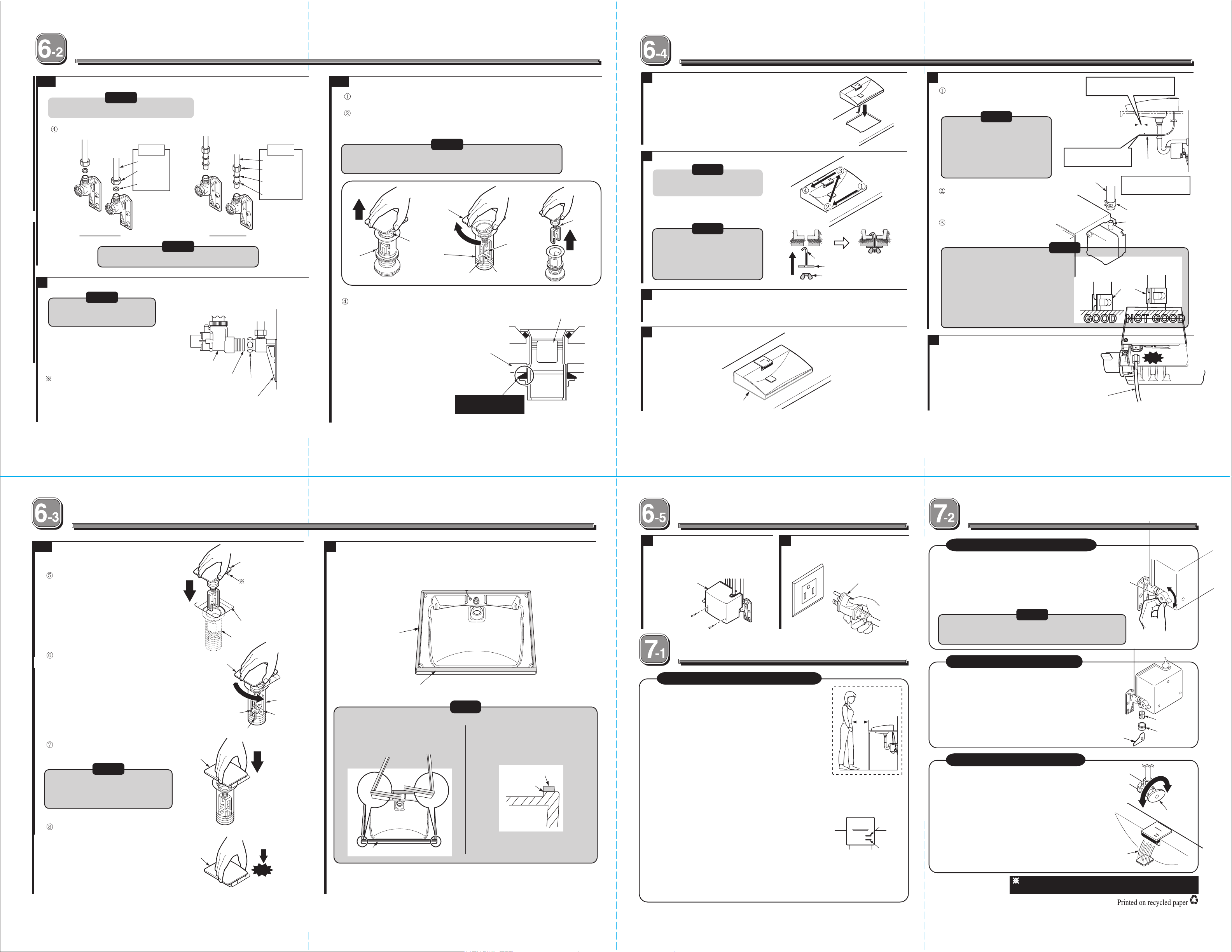
-2
3
Mount the two water inlet brackets on the wall (Continued)
Caution
Remove all the protective covers.
Connect the hot/cold water supply pipe with the water inlet brackets.
Not
included
Flexible hose
Nut
Packing
Copper pipe Flexible hose
Caution
Make sure Hot goes on the left side.
4
Connect the controller to the water inlet brackets.
Caution
Remove all the protective
covers.
After placing packing, attach the
controller to the water inlet bracket,
and then fix them with the nuts as
shown in the figure.
Controller
Not
included
Copper tube
Nut
Friction ring
Cone washer
-1
5
Install the drain assembly to the lavatory.
Detach the grid unit by pulling it.
Turn it clockwise (about 45 ° ) and pull the grid unit out of the cross-bar .
Caution
If Grid unit hook is trapped, restore the grid unit, Then turn it
clockwise again, while pulling it slowly out of the cross-bar.
Pull
Grid cup unit
Grid Unit
Drain
Assembly
After seperating the grid unit and drain assembly
body, install the drain assembly body on to the
Lavatory.
Then apply the Plumber’s Putty or Silicone caulking
around the lavatory waste oulet.
Draining
assembly body
Grid unit hook
lavatory
Cross bar
Notch
Grid unit
Horizontal hole
7
Install the lavatory
1. Cut the countertop using the template provided.
2. Carefully place the lavatory into the cut-out. For
proper installation, two people may be required to
lift and position the lavatory.
8
Attach to the counter
Caution
Fasten the hook bolts in the
order shown
Caution
Fasten the butterfly nut by hand
Do not use tools. Using tool may result in
overtighting and cause product damage
9
Apply Caulking
Apply caulk around the perimeter of the washbasin then wipe off excess. Allow to dry
for 30
minutes.
10
Drawing of finished model
Hook bolt
Washer
Butterfly nut
11
Connect spout connecting hose.
Cut the spout connecting hose to a proper
length that reaches controller water inlet
without being stretched.
Caution
●Be sure to cut the hose
carefully with a cutter, so the
surface is square.
●If the spout connecting hose is
too long, cut it to a proper
length.
Insert the spout connecting hose into
the controller water inlet.
Fix the hose with hose clamp.
● Check that the spout hose is
firmly inserted.
● Check that the spout hose is
not folded.
● Check that the hose clamp is located
at the right position.
● It is imperative to connect the spout
with hose clamp.
12
Fix the connector
Insert the vinyl cord (white) with connector
and make sure that you hear the click sound.
Cut the spout connecting hose
to a proper length.
Pay attention to the cut
section
Spout connecting
hose
Caution
Hose clamp shall be fixed right over
the controller water inlet
GOOD
90°
Spout connecting
hose
Be careful that the
hose is not folded
Hose clamp
Controller water inlet
Hose clamp
NOT GOOD
Click!
Packing is located on the water
inlet bracket.
5
-2
Install the drain to the
Lavatory (Continued)
Lower the grid unit into the
drain assembly body
Turn the grid unit counterclockwise
while putting the Grid hook unit into the
cross bar.
To make sure that the Grid unit is properly
placed on cross-bar, pull it upward.
Caution
If you can pull it out, repeat
installation procedure.
If the Grid unit is hooked to cross-bar and cannot be
pulled out, then push in the grid unit firmly until you hear
a click.
Grid
unit
Grid
unit
Packing
Grid unit
Notch
Nut
Water inlet
Grid unit
Now check that the stud at
the bottom of the cap is
positioned with the slit
on the Lavatory.
Slit on the Lavatory.
Drain
assembly
Drain Assembly
body
Cross bar
Angle
Click!
Push until you
hear a click
Apply Plumber’s Putty
or Silicone caulking
(around the lavatory waste outlet)
6
Apply packing material. Make sure surface is free of dirt
and dust.
・ Peel off the lining of the packing material, then stick the packing material to the
bottom of the lavatory.
Packing material
(large)
Packing material
(small)
Caution
● Apply the small packing material
to the rear part of the lavatory,
be sure there is no clearance
between the large and small
packing material.
Packing material (small)
● Appply the packing material so that
it match with the inner edge of the
lavatory.
Packing material
(small)
Match here
Caulking
Check the following
13
Install the controller cover
After confirming the controller is securely
attached and confirming the controller is
firmly mounted, install the controller cover.
Cover
14
Insert the power plug
Insert the power plug in the wall
outlet.
Power plug
Function Test
1.Checking after installation
Perform the follow checks after installation .
1) Check for water leakage
Open the stop valve and check for water leakage.
2) Operation
<Check the body dectection sensor>
●
Insert the power plug to the AC outlet. Then, walk to the
lavatory counter and when you are approximately 15-3/4”
.
(400mm) away from the counter, the LED light is ON.
<Check the hand washing sensor>
●Place your hands under the faucet, water begins to flow.
●Water will automatically stop in 1-2 sec later after your hand s are removed.
For safety and conservation reasons, water will stop
●
automatically after 60s of detection each use.
< Check the switches>
●Water flows when Start/Stop switch is pressed.
●To stop the water flowing, press the switch again.
●It will stop automatically after 50 seconds if switch is left ON.
●When hot/cold switch is pressed, LED switch turns red. Water r eaches its
optimal temperature
●Temperature will restore by pressing it again; LED turns back to blue .
If the product does not operate properly, contact TOTO or your plumbing contractor .
About 15-3/4”
(400mm)
Hot/cold
switch
Start/Stop
switch
senser cord
2. Temperature Adjustment
The water temperature has been factory set to 97°F
(36˚C).
Depending on the water supply pressure or other
site conditions, water temperature may not be
Temperature
control
handle
kept as specified. At this time, use the handle to
adjust the temperature.
Caution
If water temperature goes opposite direction,confirm if the
hot and cold water connection is correct.
3. Cleaning of the strainer
Close the stop valve with hand.
Use the open/close tool to remove the strainer cover.
- Clean the strainer regularly after installation.
If the strainer is blocked, the flow becomes weak,
and the product will not function properly.
Open/close tool
4. Adjustment of flow rate
The flow controller regulates flow rate to 1.7 gpm
(6.5L/min) and there is no need to adjust the flow rate.
Use the product with the stop valve fully opened.
But when water flow is too strong, adjust the flow rate
by turning the stop valve clockwise.
The water appears cascade with water
flow rate of more than 1.45 gpm (5.5 L/min).
The Instruction Manual attached to the delivery must be
provided to the customer.
Open
Hot
Cold
Strainer
Strainer cover
Close
Stop valve
 Loading...