

Toto GR TLG02301U, GR TLG02304U, GR TLG02307U, GS TLG03301U, GS TLG03303U Installation And Owner's Manual
...
Warranty Registration and Inquiry
For product warranty registration, TOTO U.S.A. Inc. recommends online warranty registration. Please visit
our web site http://www.totousa.com. If you have questions regarding warranty policy or coverage, please contact TOTO U.S.A. Inc., Customer Service Department, 1155 Southern Road, Morrow, GA 30260
(888) 295-8134 or (678) 466-1300 when calling from outside of U.S.A.
Installation and Owner’s Manual
Manual de instalación y del propietario
Manuel d’installation et d’utilisation
Manual de Instalação e do Proprietário
Single Handle Lavatory Faucet
Grifo de Lavabo de Una Manija
Robinet de Lavabo à une Manette
Faucet de Alça Única com Balcão de Banheiro
GR
TLG02301U
TLG02304U
TLG02307U
GS
TLG03301U
TLG03303U
TLG03305U
LF
TLS04301U
TLS04306U
2
ENGLISH
THANK YOU FOR CHOOSING TOTO!
The mission of TOTO is to provide the world with healthy, hygienic and more
comfortable lifestyles. We design every product with the balance of form and
function as a guiding principle. Congratulations on your choice.
Tools You Will Need............................3
Specifications.........................................3
Installation Procedure...........................4
Warranty................................................10
Rough-In Dimensions..........................26
Thanks for Choosing TOTO!...............2
Warnings...............................................2
Before Installation................................2
Care and Cleaning................................2
Included Parts.......................................3
TABLE OF CONTENTS
WARNINGS
BEFORE INSTALLATION
For safe operation of the faucet, please observe the following:
Operating Pressure:
Minimum Pressure....................20 psi (138 kPa), dynamic
Maximum Pressure...................80 psi (551 kPa), static
Do not use the product at an ambient temperature below 32º F (0º C)
Observe all local plumbing codes.
Before installing the faucet, be sure to thoroughly flush the supply pipes of dirt
and debris.
Make sure the water supply is shut off at the stop valve.
Read these instructions carefully to ensure proper installation.
TOTO reserves the right to update product design without notice.
Your new faucet is designed for years of trouble-free performance. Keep it
looking new by cleaning it periodically with mild soap, rinsing thoroughly
with warm water and drying with a clean, soft cloth. Do not use abrasive
cleaners, steel wool or harsh chemicals, as thes will dull the finish. Failure to
follow these instructions may void your warranty
CARE AND CLEANING
3
ENGLISH
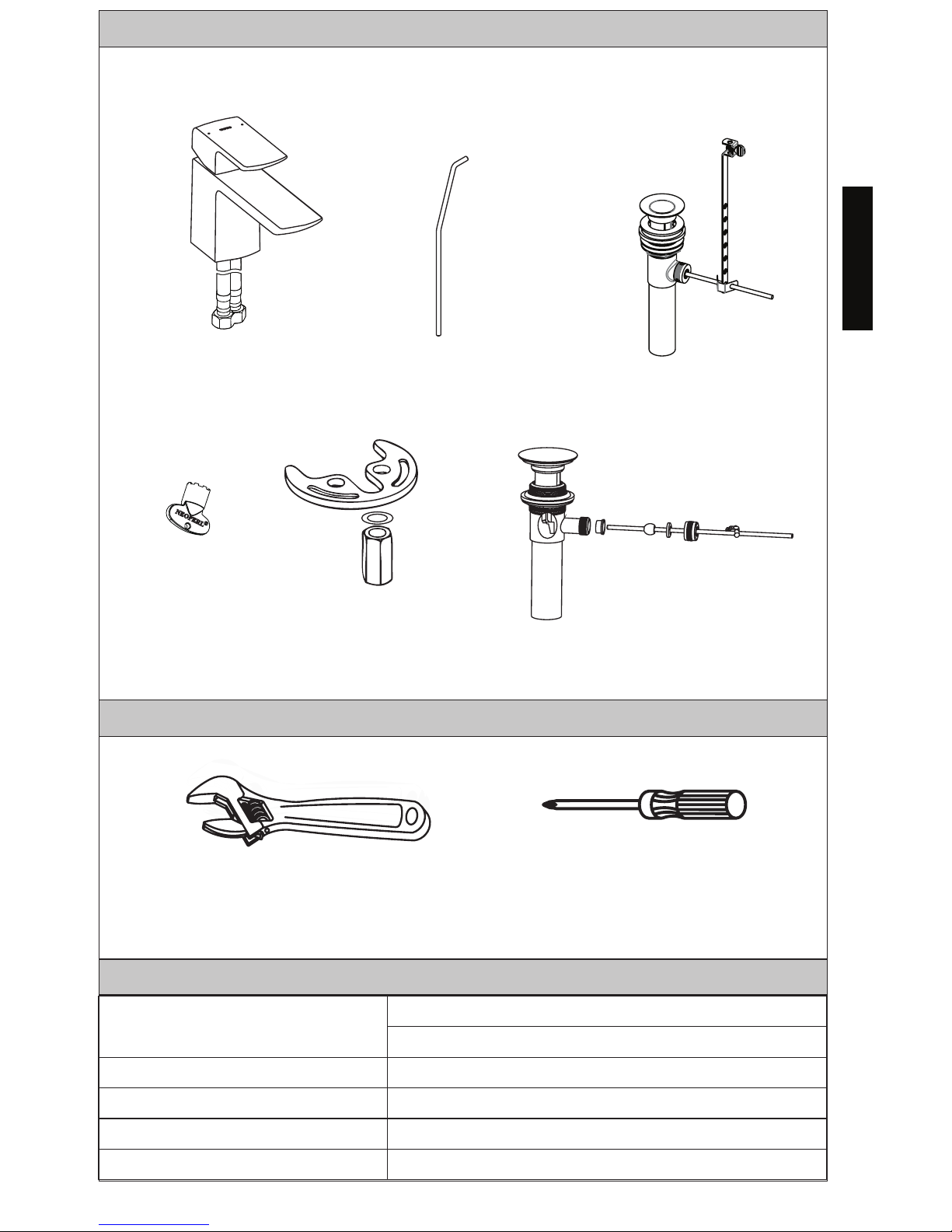
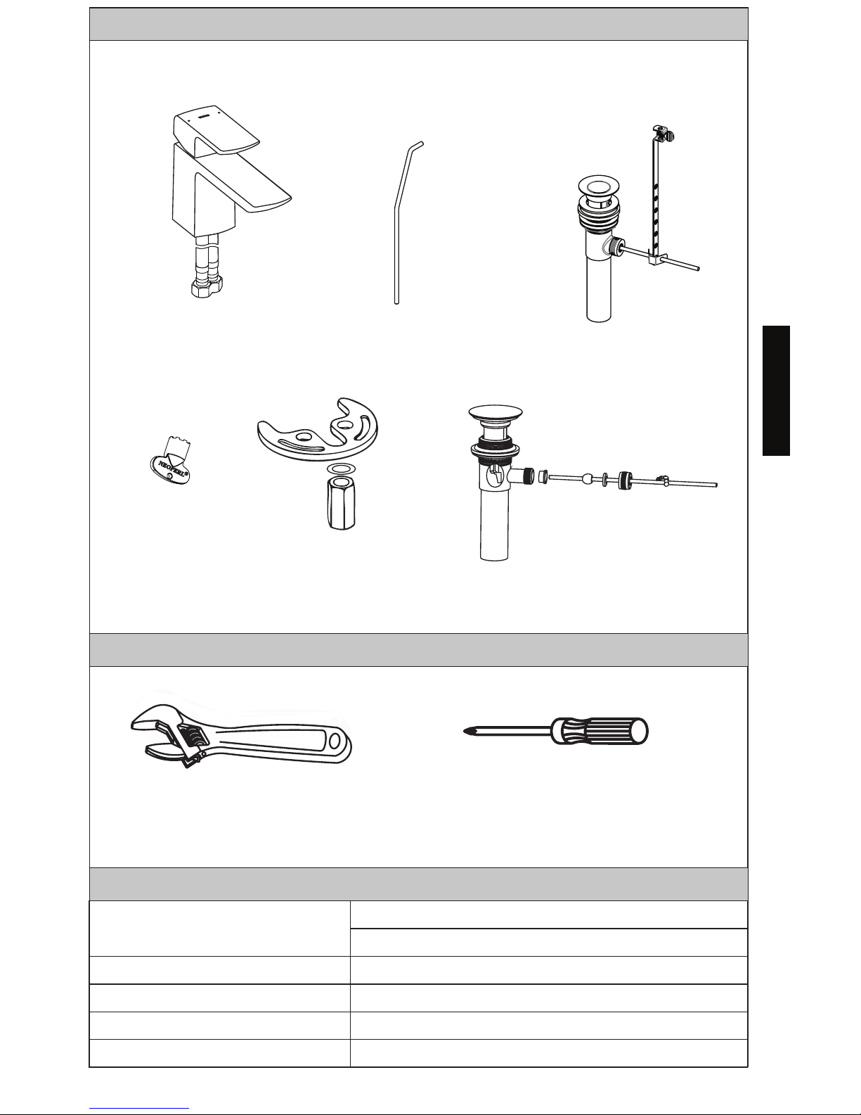
INCLUDED PARTS
TOOLS YOU WILL NEED
SPECIFICATIONS
Adjustable
Wrench
Drain Lift Rod*
LF Drain Assembly
GR GS Drain Assembly
Spout Mounting
Hardware
Spout Assembly*
Water Supply Pressure
Minimum required: 20 psi (138 kPa) (Flowing)
Maximum allowed: 80 psi (551 kPa)
Water Supply Connection 3/8 Comp
Ambient Temperature 32~104°F (0~40°C)
Humidity Max. 90% RH
Flow Rate Maximum 1.2 gallon/min (4.5 L/min)
Aerator
Key
Check to make sure you have the following parts indicated below:
Phillips
Screwdriver
4
ENGLISH
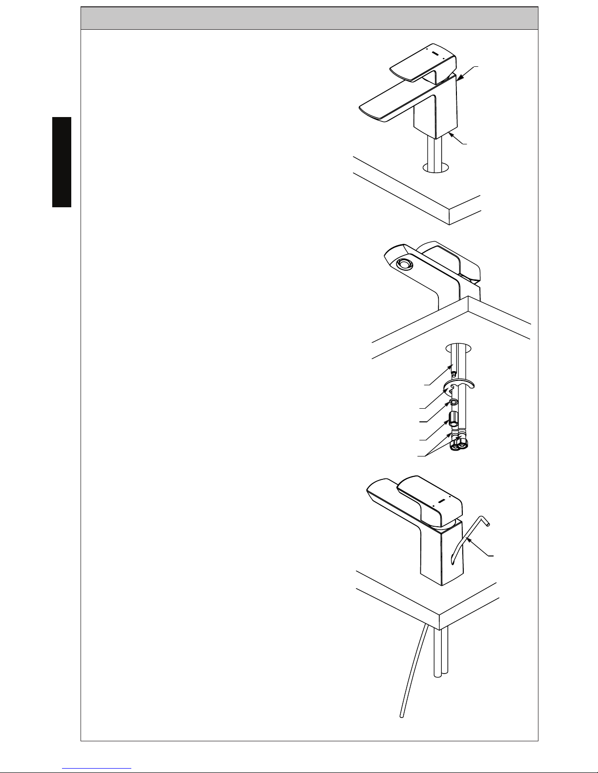
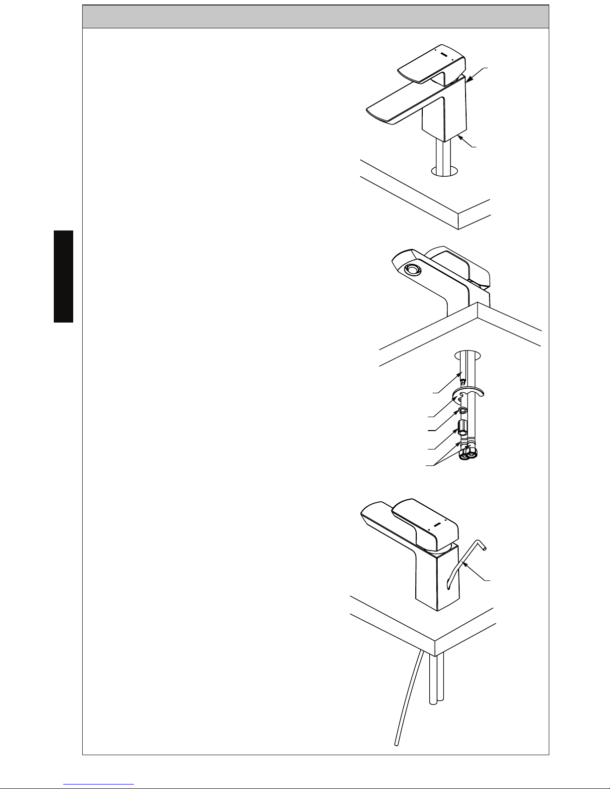
INSTALLATION PROCEDURE
Faucet
1. Place gaskets under spout.
Pass the supply hoses and mounting
studs through the mountin holes until the
spout comes to rest.
2. Orient the spout as needed. From
below the mounting surface, place the
crescent shaped washer over the mounting studs as shown.
Fasten the mounting nuts to the studs to
secure the spout.
Tighten with wrench as needed.
Connect the hoses to the supply lines.
The left hose (marked with red band)
connects to the hot water supply. The
right hose connects to the cold water
supply.
Tighten with wrench as needed.
Spout Body
Gasket
3. Insert the drain lift rod through the opening in the back of spout.
Mounting Studs
Washer
Spring Washer
Mounting Nut
Supply Hoses
Drain
Lift Rod
5
ENGLISH
INSTALLATION PROCEDURE
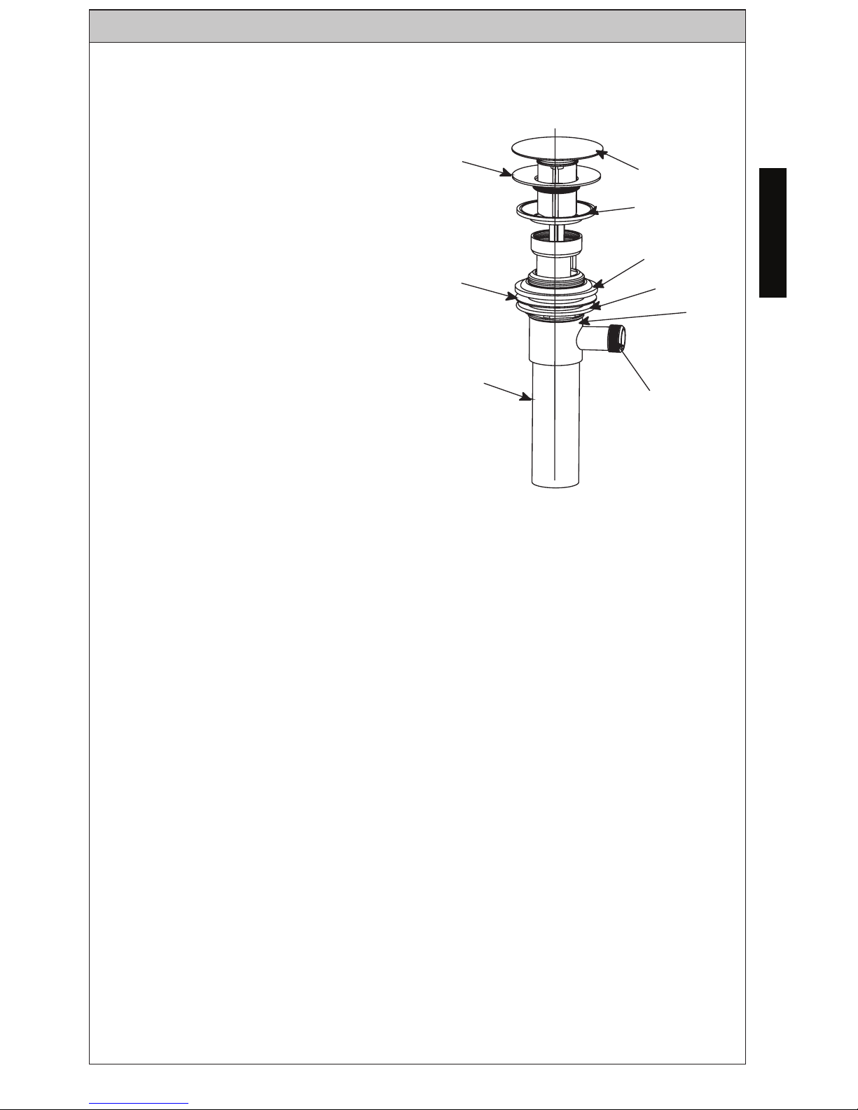
Drain
4. Remove the plunger, flange and
gasket from the drain assembly by
unfastening the flange and pulling
these parts from the drain.
Insert the drain body up thorugh the
drain hole from below the lavatory. If
necessary, turn the nut and push the
washer and gasket (thick) down to
allow for clearance.
While holding the drain body in
place, fasten the flange to the drain
body from the top. Ensure that the
gasket is between the flange and
the lavatory as shown. Once the
flange is fully seated, turn the nut
below the lavatory up until a good
seal is formed. Do NOT overtighten!
Reinsert the plunger if needed.
Flange
Plunger
Gasket
(thick)
Gasket
Washer
Nut
Body
Lever
screw
hole
Tail pipe
6
ENGLISH
INSTALLATION PROCEDURE
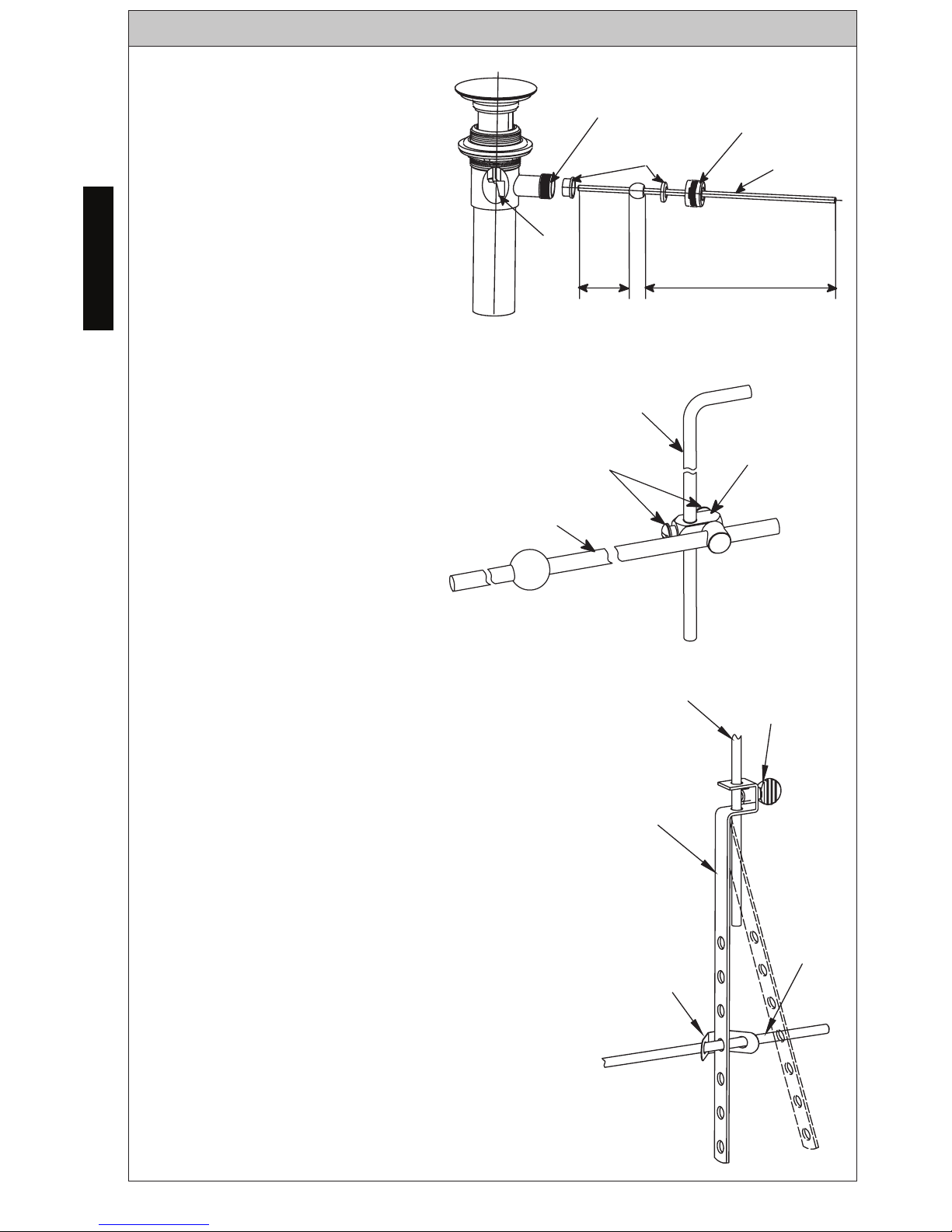
5. Prepare the pivot arm by
placing one bushing on each
side of the pivot ball as shown.
Insert the short end of the rod
into the drain body and through
the eyelet hole in the plunger.
Fasten the pivot ball nut to
secure.
For LF series drain
Insert the drain lift rod thorugh the two (2)
holes in the square end of the connector
rod.
Slide the connector rod up the drain lift
rod to a suitable location so that the pivot
arm can pass through one of the mounting
holes as shown.
Secure the connector rod to the pivot
arm using the spring clamp. One end of
the spring clamp will need to be on the
pivot arm before the connector rod is assembled.
Tighten the thumb screw in the connector
rod to secure it to the drain lift rod.
Conduct tests to ensure all the linkages are
working properly and no leaking occurs.
Adjust if needed.
Drain lift
rod
LF Series
Thumb
screw
Connector
rod
Connecting
spring piece
Pivot Arm
Lever
hole
Plunger
Short
end
Long
end
Bushings
Pivot Ball
Nut
Pivot Arm
Drain
lift rod
GR GS Series
Screw
Pivot
arm
Drain lift rod
connecting part
For GR-GS series drain
Insert the drain lift rod and
pivot arm into the drain lift
rod connecting part.
Tighten both rods with
screwdriver.
7
ENGLISH
WARRANTY
1. TOTO ers (“Product”) to be free from defects in
materials and workmanship during normal use when properly installed and serviced, for a period of three (3) years
from date of purchase. This limited warranty is extended only to the ORIGINAL PURCHASER of the Product and is
not transferable to any third party, including but not limited to any subsequent purchaser or owner of the Product.
This warranty applies only to TOTO Product purchased and installed in North, Central and South America.
2. TOTO’s obligations under this warranty are limited to repair, replacement or other appropriate adjustment, at
TOTO’s option, of the Product or parts found to be defective in normal use, provided that such Product was properly
sa snoitcepsni hcus ekam ot thgir eht sevreser OTOT .snoitcurtsni htiw ecnadrocca ni decivres dna desu ,dellatsni
ni strap ro robal rof egrahc ton lliw OTOT .tcefed eht fo esuac eht enimreted ot redro ni yrassecen eb yam
connection with warranty repairs or replacements. TOTO is not responsible for the cost of removal, return and/or
reinstallation of the Product.
5. THIS WARRANTY GIVES YOU SPECIFIC LEGAL RIGHTS. YOU MAY HAVE OTHER RIGHTS WHICH VARY
FROM STATE TO STATE, PROVINCE TO PROVINCE OR COUNTRY TO COUNTRY.
6. To obtain warranty repair service under this warranty, you must take the Product or deliver it prepaid to a TOTO
service facility together with proof of purchase (original sales receipt) and a letter stating the problem, or contact
a TOTO distributor or products service contractor, or write directly to TOTO U.S.A., INC., 1155 Southern Road,
Morrow, GA 30260 (888) 295 8134 or (678) 466-1300, if outside the U.S.A. If, because of the size of the Product
or nature of the defect, the Product cannot be returned to TOTO, receipt by TOTO of written notice of the defect
esoohc yam OTOT ,esac hcus nI .yreviled etutitsnoc llahs )tpiecer selas lanigiro( esahcrup fo foorp htiw rehtegot
to repair the Product at the purchaser’s location or pay to transport the Product to a service facility.
THIS WRITTEN WARRANTY IS THE ONLY WARRANTY MADE BY TOTO. REPAIR, REPLACEMENT OR OTHER APPROPRIATE
ADJUSTMENT AS PROVIDED UNDER THIS WARRANTY SHALL BE THE EXCLUSIVE REMEDY AVAILABLE TO THE ORIGINAL
PURCHASER. TOTO SHALL NOT BE RESPONSIBLE FOR LOSS OF THE PRODUCT OR FOR OTHER INCIDENTAL, SPECIAL
OR CONSEQUENTIAL DAMAGES OR EXPENSES INCURRED BY THE ORIGINAL PURCHASER, OR FOR LABOR OR OTHER
COSTS DUE TO INSTALLATION OR REMOVAL, OR COSTS OF REPAIRS BY OTHERS, OR FOR ANY OTHER EXPENSE NOT
SPECIFICALLY STATED ABOVE. IN NO EVENT WILL TOTO’S RESPONSIBILITY EXCEED THE PURCHASE PRICE OF THE
PRODUCT. EXCEPT TO THE EXTENT PROHIBITED BY APPLICABLE LAW, ANY IMPLIED WARRANTIES, INCLUDING THAT
OF MERCHANTABILITY OR FITNESS FOR USE OR FOR A PARTICULAR PURPOSE, ARE EXPRESSLY DISCLAIMED. SOME
STATES DO NOT ALLOW LIMITATIONS ON HOW LONG AN IMPLIED WARRANTY LASTS, OR THE EXCLUSION OR
LIMITATION OF INCIDENTAL OR CONSEQUENTIAL DAMAGES, SO THE ABOVE LIMITATION AND EXCLUSION MAY NOT
APPLY TO YOU.
3. This warranty does not apply to the following items:
b. Damage or loss resulting from any accident, unreasonable use, misuse, abuse, negligence, or improper
care, cleaning, or maintenance of the Product.
c. Damage or loss resulting from sediments or foreign matter contained in a liquid soap system.
ro/dna hsrah a ni tcudorP eht fo noitallatsni morf ro noitallatsni reporpmi morf gnitluser ssol ro egamaD .d
tion of the Product.
e. Damage or loss resulting from electrical surges or lightning strikes or other acts which are not the fault of
f. Damage or loss resulting from normal and customary wear and tear, such as gloss reduction, scratching or
fading over time due to use, cleaning practices or water or atmospheric conditions, including but not limited
to, the use of bleach, alkali, acid cleaners, dry (powder) cleaners or any other abrasive cleaners or the use
of metal or nylon scrubbers.
4. In order for this limited warranty to be valid, proof of purchase is required. TOTO encourages warranty registration
upon purchase to create a record of Product ownership at http://www.totousa.com is required. TOTO encourages
registration upon purchase and failure to register will not diminish you r limited warranty rights.
8
ESPAÑOL
¡GRACIAS POR ELEGIR TOTO!
La misión de TOTO es proporcionar al mundo estilos de vida saludables,
higiénicos y más cómodos. Diseñamos cada producto con el equilibrio de
forma y función como principio rector. Felicidades por tu elección.
Herramientas que Necisitara.............9
Especificaciones.....................................9
Procedimiento de Montaje...................10
Garantia................................................13
Bosquejo...............................................26
¡Gracias por elegir TOTO!................8
Advertencias.......................................8
Antes de la Instalacion.......................8
Cuidado y Limpieza............................8
Partes Incluidas...................................9
TABLA DE CONTENIDO
ADVERTENCIAS
ANTES DE LA INSTALACIÓN
Para un funcionamiento seguro del grifo, tenga en cuenta lo siguiente:
Presión operacional:
Presión mínima .................... 20 psi (138 kPa), dinámica
Presión máxima ................... 80 psi (551 kPa), estático
No use el producto a una temperatura ambiente inferior a 32º F (0º C)
Observe todos los códigos de plomería locales.
Antes de instalar el grifo, asegúrese de enjuagar a fondo los tubos de
suministro de suciedad y residuos.
Asegúrese de que el suministro de agua esté cerrado en la válvula de cierre.
Lea estas instrucciones cuidadosamente para asegurar una instalación correcta.
TOTO se reserva el derecho de actualizar el diseño del producto sin previo
aviso.
Su nuevo grifo está diseñado para años de rendimiento sin problemas.
Mantenga su aspecto como nuevo limpiando periódicamente con jabón
suave, enjuague bien con agua tibia y seque con un paño limpio y suave. No
use limpiadores abrasivos, lana de acero o productos químicos agresivos,
ya que éstos opacarán el acabado. El incumplimiento de estas instrucciones
puede anular la garantía
CUIDADO Y LIMPIEZA
9
ESPAÑOL
PARTES INCLUIDAS
HERRAMIENTAS QUE NECESITARÁ
ESPECIFICACIONES
Llave
Ajustable
Vara de Desagüe*
Ensamblaje de Desagüe LF
Ensamblaje de
Desagüe GR GS
Equipo de Montura
de Grifo
Ensamblaje de Salida
para Tina
Presión de suministro de agua
Minimo requerido: 20 psi (138 kPa) (Fluyendo)
Máximo Permitido: 80 psi (551 kPa)
Tipo de Conneccion 3/8 Comp
Temperatura ambiente 32~104°F (0~40°C)
Humedad Max. 90% RH
Flujo Maximo 1.2 gallon/min (4.5 L/min)
Llave del
Aireador
Controle para asegurarse de que tiene las partes indicadas a continuación:
Destornillador
Phillips
10
ESPAÑOL
PROCEDIMIENTO DE MONTAJE
Llave
1. Coloque las juntas debajo de la salida
para tina.
Pase las mangueras de suministro y los
pernos de montaje a través de los orificios de montaje hasta que la salida para
tina se afloje.
“2. Oriente la salida para tina según su
necesidad. De la superficie de montaje
inferior, coloque la arandela en forma de
medialuna sobre los pernos de montaje
como se muestra.
Ajuste las tuercas de montaje a los pernos para asegurar la salida para tina.
Ajuste con la llave lo necesario.
Conecte las mangueras a las líneas
de suministro. La manguera izquierda
(marcada con una banda roja) conecta el suministro de agua caliente. La
manguera derecha conecta el suministro
de agua fría.
Ajuste con la llave lo necesario.
Cuerpo de
pico
Junta
3. Inserte la vara de desagüe a través de
la abertura de la parte trasera de la salida
para tina.
Pernos de
Montaje
Arandela
Arandela de
Resorte
Tuerca de Montaje
Mangueras de
suministro
Vara de
Desagüe
 Loading...