

Toto EcoPower TET1GN(32)#CP, EcoPower TEU1GN(12)#CP, EcoPower TEU1LN(22)#CP, EcoPower TET6GN(32)#CP, EcoPower TEU1LN(12)#CP Installation Manual
...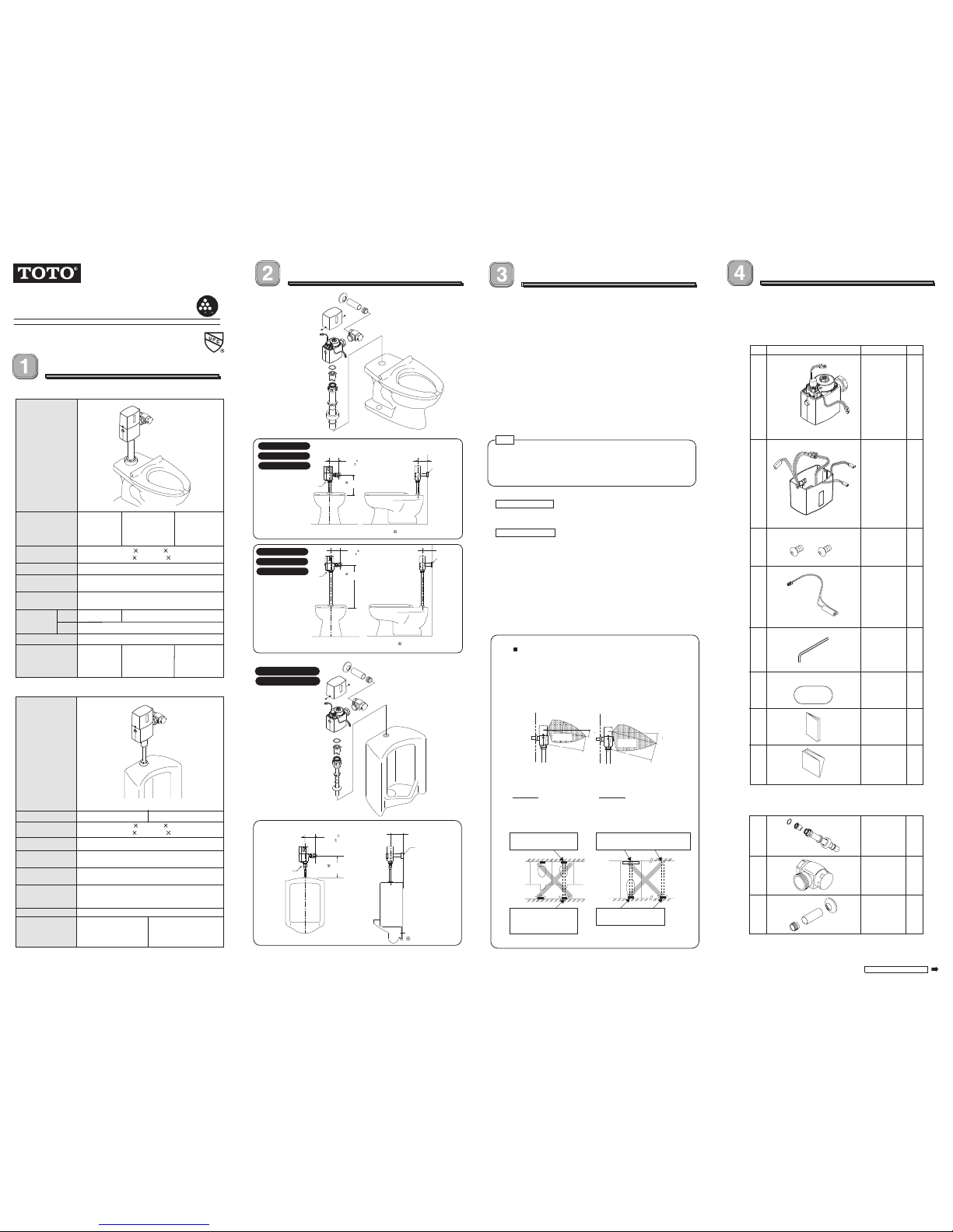
Variation & Specification
INSTALLATION MANUAL
Set-up Drawing
Model number
Figure
Approx. 1.6
gallon (6L)
Approx. 3.5
gallon (13L)
c
Connection of the
water supply pipe
Supply water
pressure
Shutoff pressure
Discharge quantity
per flush at 28 PSI
(196kPa)
(Factory set)
7 PSI (48kPa)
1"NPT
Model number
Detection time
Urinal Flush Valve
6 seconds or more
Detection time
6 seconds or more
Approx. 1.0 gallon
(3.8L)
Ambient temperature
Connection of the
water supply pipe
Supply water
pressure
Shutoff pressure
Discharge quantity
per flush at 28 PSI
(196kPa)
(Factory set)
Minimum required water pressure: 15 PSI (103kPa)
(flowing)
Maximum water pressure: 125 PSI (862kPa)
7 PSI (48kPa)
32-104˚F (0-40˚C)
Water temperature 34-104˚F (1-40˚C)
3/4"NPT
Check local codes
TET1GN32#CP
Installation Precautions
Toilet Flush Valve
1. Prior to Installation
Prior to Installing your TOTO®`s E coPower®Flush Val ve, install the items
listed bellow:
· Closet fixture/Urinal fixture
· Drain line
· Water supply line
The supply piping to these devices shall be securely anchored to the
building structure to prevent the installed device from having unnecessary
movement when operated by the user. Care shall be exercised when
installing the device to prevent marring the exposed surface.
2. Important
All plumbing is to be installed in accordance with applicable codes
and regulations. Water supply lines must be sized to provide an
adequate volume of water for each fixture.
Flush all waterlines prior to operation.
The minimum pressure required to the valve is determined by the type
of fixture selected. Consult fixture manufacturer for pressure requirement.
Do not use toothed tools to install or service the valve.
Be sure to install TOTO®`s EcoPower®Flush Valve so that the control stop
is sit uated no more tha n 11- 1/2"(292 mm) above the top of the bowl or
the urinal. Referto local codes for special requirements.Except for
TET6GN#CP,
TEW6GN#CP and TET6LN#CP
, make sure that the control
stop is installed 27" adove the
top of the bowl for proper valve function.
3. Use carenot to damagethe surface ofthe infrared sensor.
4. For ToiletFlush Valve
The toilet sensor valve may not function if toilet seat and/or lid cover are
left upright as it may block the sensor.
5. For Urinal Flush Valve
The Urinal Flush Valve is designed to be used with a washout urinal
for optimum performance. However, a siph on jet uri nal may als o be
substitu ted. B lowout urinals are not recommended.
6. The detectionrange of the infrared sensoris shown in the figureabove.
Do not install a handrail or any other object within the detection zone
of the sensor, as any object blocking the sensor may cause the valve to
malfunction. Additionally, to avoid the possibility of valve malfunction, do not
install the flu sh valv e in a locatio n where the se nsor f aces a mi rror,
stainless steel wall, other highly reflective surface or another infrared sensor.
Tobe continued on the back
Figure
Note
Components
1. Required tools
Adjustabl e wrench, Phil lips and slott ed screwdriver s.
2. Inspection
Unpack the flush valve and carefully make sure the co ver, main unit and
all other parts are i ncluded a nd intact before starting installation of the
product.
Item Figure Description Q’ty
A
Valve Body
assembly
1
B
Top cover
assembly
1
C
D
Screw 2
F
Back-up
battery Pack
1
G
Tool
(Allen wrench)
1
H
Notice Label
1
Owner's
Manual
1
1
Toilet Flush Valve
For TET1GN32#CP, TEW1GN32#CP, TET6GN32#CP,
I
Vacuum
breaker tube
(with spud
joint)
1
J Control stop
1
K
Sweat
solder kit
(Escutcheon,
covering tube,
adapter)
1
E
T
O
T
O
Forthe best results, be sure to read the following installation instructions and use the product only as described in this manual.
Ambient temperature
32-104˚F (0-40˚C)
Water temperature 34-104˚F (1-40˚C)
Dimension of Cover
7-3/4" (H) 4-1/2"(W) 3-1/8"(D)
(198mm(H) 115mm(W) 80mm(D))
Dimension of Cover
7-3/4" (H) 4-1/2"(W) 3-1/8"(D)
(198mm(H) 115mm(W) 80mm(D))
Installation
Manual
(this manual)
03585T3R
11-1/2"
(292mm)
1-1/2"
NPSM
Min.2-1/4"(57mm)
3/4"NPT
inlet supply
EcoPower®Flush Valve
4-3/4" 1/2"
(120 13mm)
4-3/4" 1/2"
(120 13mm)
Min.2-1/4"
(57mm)
1"NPT
inletsupply
11-1/2"
(292mm)
Check local codes
1-1/2"
NPSM
4-3/4" 1/2"
(120 13mm)
Min.2-1/4"
(57mm)
1"NPT
inletsupply
27"
(686mm)
Check local codes
1-1/2"
NPSM
Detection zone
The detection zone is self-adjusting and is equipped with a
3-second flush delay. (No flush delay for Urinal flush valve)
The detection zone may differ according to the color of the
user’s clothes.
When a user wears black clothes, the detection zone may
become smaller and the valve may not flush.
“AVOID”
DO NOT place the Infrared
stainless steel wall, or other
highly reflective surface.
Mirror, Stainless steel wall or
other highly reflective surface.
Infrared sensor of the
another automatic
flush valve.
Infrared sensor of the
automatic flush valve.
“AVOID”
DO NOT place the Infrared
sensor of one urinal so that sensor in front of a mirror,
it is in line with the sensor
of another automatic f lush
valve sensor.
Infrared sensor of the
automatic flush valve.
L
Max19-11/16"
(Max500 mm)
Max31-1/2"
(Max800 mm)
15
L
Max21-1/4"
(Max550 mm)
Max33-1/2"
(Max850 mm)
20
TET1LN(32)#CP
TET6LN(32)#CP
TEU1GN(12,22)#CP
TET1GN(32)#CP
TET6GN(32)#CP
TEU1LN(12,22)#CP
TEW1GN(32)#CP
TEW6GN(32)#CP
Approx. 1.28
gallon (4.8L)
Approx. 0.5 gallon
(1.9L)
Minimum
(Flowing)
Maximum
15 PSI (103kPa)
125 PSI (862kPa)
35 PSI (241kPa)
TET6GN(32)#CP
TEW6GN(32)#CP
TET1LN(32)#CP
TEU1LN(12,22)#CP
TET1GN(32)#CP
TEU1GN(12,22)#CP
TEW1GN(32)#CP
TEW1LN(32)#CP
TEW1GN32#CP
TET1LN32#CP
TET6GN32#CP
TEW6GN32#CP
TET6LN32#CP
TEU1GN(12,22)#CP
TEU1LN(12,22)#CP
TEW6GN32#CP, TEU1GN(12, 22)#CP, TET1LN32#CP,
TET6LN32#CP AND TEU1LN(12, 22) #CP
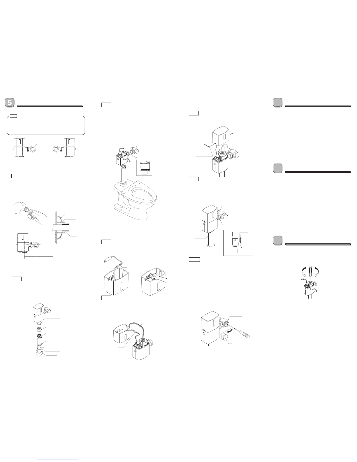
Installation Procedure Test Run
Note to the installer
7
6
Adjustment
Step 1 (For New Installation)
Escutcheon
White
White(Toilet type)
Yellow(Urinal type)
Yellow
Battery
Covering tube
Control Stop
Adapter
Min.4-1/4"(107mm)
Max.5-1/4"(133mm)
Install the control stop using a proper size escutcheon and
1. For left water supply, attach the sensor top cover in the
opposite direction so that the sensor will be at the front.
2. For retrofit installation, remove the old flush valve after
shutting off the control stop.
swea t sol der a dapter kit if applica ble. Thread seali ng
compounds should be used on male NPT threads only. The
distance from center of the control stop to center of the flush
valve should fall within 4-1/4" to 5-1/4"(107mm to 133mm).
Step 2
Determine the length of vacuum breaker tube to join the
flush valve and fixture spud. Cut the vacuum breaker tube,
if r equired, to the prope r length. Assemble t he spud nut
assembly to the fixture spud. Hand tighten spud nut to
fixture.
For sweat solder
Right Water Supply Left Water Supply
Step 5
Connect the connectors of solenoid valve
and generator with those of controller.
Step 3
Prior to inserting the flush valve tailpiece into the control stop,
be certain that the O-ring is in the groove at the end of the
tailpiece, the locking nut and the snap ring are located as
shown. Connect the flush valve with the control stop and the
vacuum breaker tube. Care should be taken not to damage the
O-ring when inserting the tailpiece into the control stop.
If lubrication is needed, wetting the O-ring with water will be
sufficient. Align the flush valve and securely tighten fixture spud
nut, vacuum breaker tube nut and locking nut with a wrench.
Step 4
Connect the connector of the battery with that of the controller
and set it at the proper position as shown below.
Step 6
Fas ten the senso r to p c over on body cov er w ith the
supplied screws (use supplied allen wrench).
Step 7
Before the s upply wat er is turned on, be sure all wa ter
leaks are eliminated by tightening all the pipe connections.
If for a ny rea son it becom es ne cessary to r emove the
control stop , be certain the water is shut off at the main
supply valve.
Pipe connection
Pipe connection
Pipe connection
Escutcheon
Joint tube
Cap
Step 8
The flush valves are preset for fixture volume as marked
on the valve carton. The valve does not require adjustment
for variati on in water pressure within its operating range.
To s et t he fl ush valve for prop er o perati on, open the
control stop completely by using the adjusting screw and
flush the flush valve several times. Gradually adjust the
control stop closed, using the adjusting screw, so that the
rate of water flow into the fixture is not excessive, yet is
sufficient to adequately evacuate the waste. The cap for
the co ntrol stop should be placed after final adjust ments
have been made.
Tighten the cap firmly with a wrench.
1. Make sure the control stop is open.
2. Sit on the toilet seat. (for Toilet flush valve)
Stand within two feet from the front of the flush valve.
(for Urinal flush valve)
3. Stay there for 6 seconds or more and then leave the
toilet seat or the urinal. The valve will automatically flush.
4. Press the manual flushing button and make sure the
valve flushes properly and the sensor red light is on for
2 seconds.
5. Recheck all the pipe connections for water leaks. If the
flush valve is not operati ng properly following t he test
run consult the Troubleshooting section of the Owner's
Manu al.
After the flush valv e uni t has been inst alled correct ly,
please explain to your customer how to use it and tell them
to observe the following instructions.
1. Do not put any object in fron t of the sensor window
wh ich c oul d obs tru ct th e se nso r, ca usin g it to
malfunction.
2. For troubleshooting, consult the Owner's Manual.
If you lack t he ne cessary skills requ ired o r hav e
diffi culty follow ing t he d irection s fo r ins tallati on,
ma inte nan ce, re pai rs, tr oubl esh ooti ng or
adjustments, of the product, do not proceed without
he lp from a qu alif ied pe rso n t o a ssi st you in
performing any of these functions.
1. Adjustment of the discharge quantity
(1) Remove the sensor top cover.
(2) Adjust the discharge quantity by rotating the screw
on the piston valve.
2. Adjustment of the flow rate
Adjust the flow rate by turning the screw of the control
stop.
Turn the screw to the right to decrease the flow rate and
turn it to the left to increase.
3. Adjustment of the detection range
The detection range of the i nfrared sensor does not
need to be adjusted because it has been factory-preset.
Printed in September, 2007
8
Friction Washer
Vacuum Breaker
Tube Nut
Spud Nut
Slip Gasket
Rubber Gasket
Escutcheon
To increase To decrease
Control stop
Note
Control stop
Snap ring
O-ring
Supplied
Allen wrench
 Loading...