

Page 1
Warranty Registration and Inquiry
For product warranty registration, TOTO U.S.A. Inc. recommends online warranty registration. Please visit our web site
http://www.totousa.com.If you have questions regarding warranty policy or coverage, please contact TOTO U.S.A. Inc.,
Customer Service Department, 1155 Southern Road, Morrow, GA 30260 (888) 295-8134 or (678) 466-1300 when calling
from outside of U.S.A.
Installation and Owner’s Manual
Manual de Instrucciones y del Propietario
Manuel d’Installation et d’Utilisation
Manual de Instalação e do Proprietário
EcoPower® Automatic Faucets
Grifos Automáticos EcoPower®
Robinets Automatiques EcoPower®
Torneiras e Misturadores Eletrônicos Self Power
Page 2
2
TABLE OF CONTENTS
THANK YOU FOR CHOOSING TOTO!
The mission of TOTO is to provide the world with healthy, hygienic and more comfortable
lifestyles. We design every product with the balance of form and function as a guiding
principle. Congratulations on your choice.
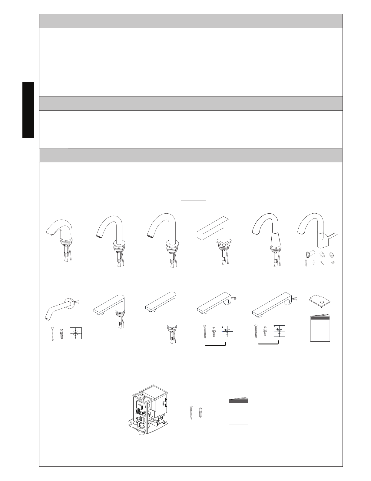
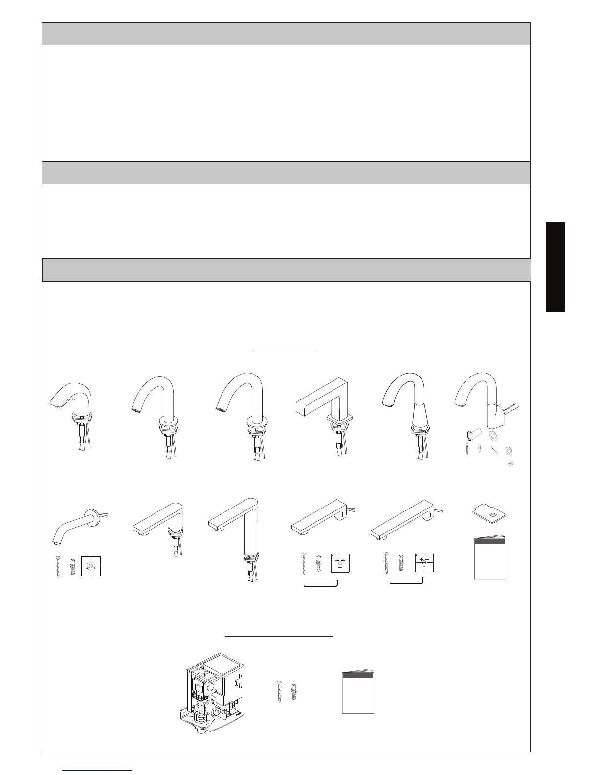
INCLUDED PARTS
Check to make sure you have all these parts from the package*:
(Appearance of some components may vary depending on the model)
SPOUT
CONTROLLER
STD
TELS10*
Gooseneck-Wall
Helix-Wall
TELS13*
Helix
TELS11* TELS16*
Helix-M
TELS12*
Axiom
TELS14*
Gooseneck
TELS15*
UP
UP
Libella Libella-M Libella Wall Libella-M Wall
TELS1C* TELS1D* TELS1A* TELS1B*
ENGLISH
Thanks for Choosing TOTO!
.................... 2
Included Parts .............................................. 2
Warnings .................................................... 3
Before Installation .....................................
3
Initializing the EcoPower Product .............
3
........................................
..............................
Care & Cleaning
Periodic Maintenance
7
Specifcations ...............................................
9
Troubleshooting .........................................
9
Warranty .....................................................10
Rough-In Dimensions ................................38
7
Installation Procedures .............................. 4
Page 3
3
ENGLISH
BEFORE INSTALLATION
Observe all local and plumbing codes.
Check the cold and/or hot water supply pressure.
The recommended working pressure range is 20 psi - 80 psi (138 kPa - 551 kPa).
If the supply pressure is higher than 80 psi (551 kPa), reduce to within recommended
range by using a pressure reducing valve (sold separatery).
Check the temperature of the water supply.
The recommended supply temperature range is 39°F - 104°F (4°C - 40°C)
Never use steam as a hot water supply.
Flush all water lines prior to installation.
Other precautions before you begin:
Pay special attention so that the sensor surface is not flawed or scratched during the
installation process.
Make sure that all pipework, stop valves, and connection lines are installed according
to local codes.
Do not place other devices that use an inverter or infrared sensor near the faucet,
as this may cause the faucet to malfunction.
Water pressures over 80 psi are not recommended for most plumbing fixtures. Check your
local plumbing code for details.
WARNINGS
Please read and adhere to the following notes. Failure to do so could result in personal
injury and/or property damage.
No person other than a service engineer should disassemble, repair or modify this faucet,
unless it is specifically described in this manual. Failure to do so may result in electric
shock or product malfunction.
Only set your faucet to the temperatures allowed in your local codes.
Do not use this faucet in a humid location where running water or condensation may
collect on the surface, especially in a sauna or steam room.
Do not strike or kick the faucet or controller box, as this may damage the unit or cause a leak.
Do not touch the hot surface of the stop valve of the controller, as it may be very hot.
Disconnect the backup battery connector when the faucet is not in use for a long period of time.
Always close the stop valve(s) before cleaning the strainer.
Periodically check the piping for leaks.
If the room temperature drops to freezing, wrap the pipes with insulation.
Make sure the power cord does not come in contact with the hot water supply pipe.
Avoid placing any objects within the detection range of the infrared sensor.
INITIALIZING THE ECOPOWER PRODUCT
Please note that it will take at least 5 minutes
after connecting the battery for the electronics to initialize.
This delay is a normal part of start up.
(Refer to Page 6 for more information)
Page 4
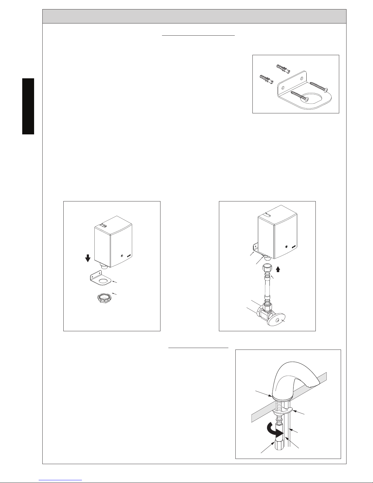
NOTE: Before installing the product, be sure to thoroughly flush the supply pipes of dirt and
debris. Shut off the water supply at the stop valves after flushing.
Install the Controller
4
ENGLISH
INSTALLATION PROCEDURE
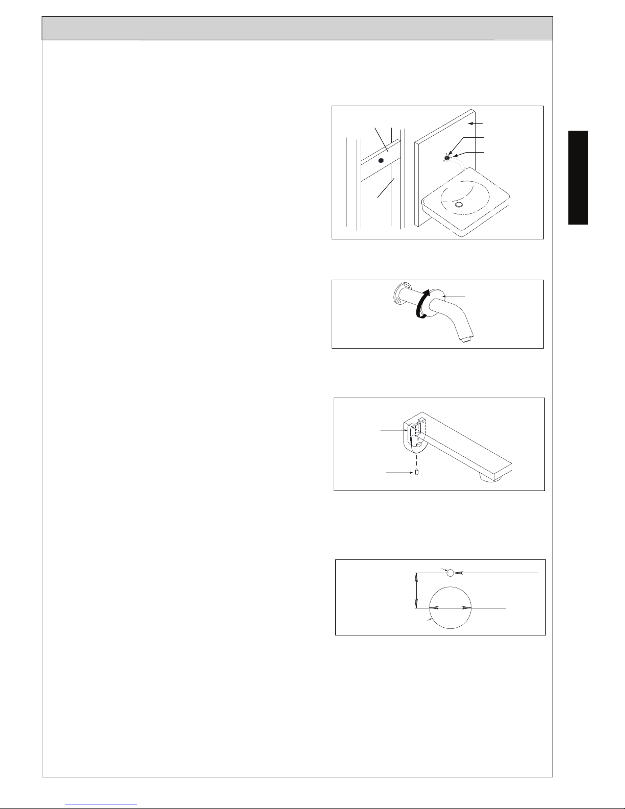
To Install Deck-Mounted Models (ill. 4):
Secure the spout to the countertop with the included
bracket and hexagonal nut. Make sure that the spout
is mounted with the tip directed towards the center
of the basin.
Install the Spout
SPOUT
ill. 4
NOTE:
If using a thermostatic valve (sold separately), please refer to its installation manual for
details.
ill. 2
ill. 3
Nut
Spout connecting
hose
Sensor cord
Gasket
Mounting Bracket
Mount Bracket
Nut
ill.1
Supply Hose
Mount Bracket
Nut
Stop valve
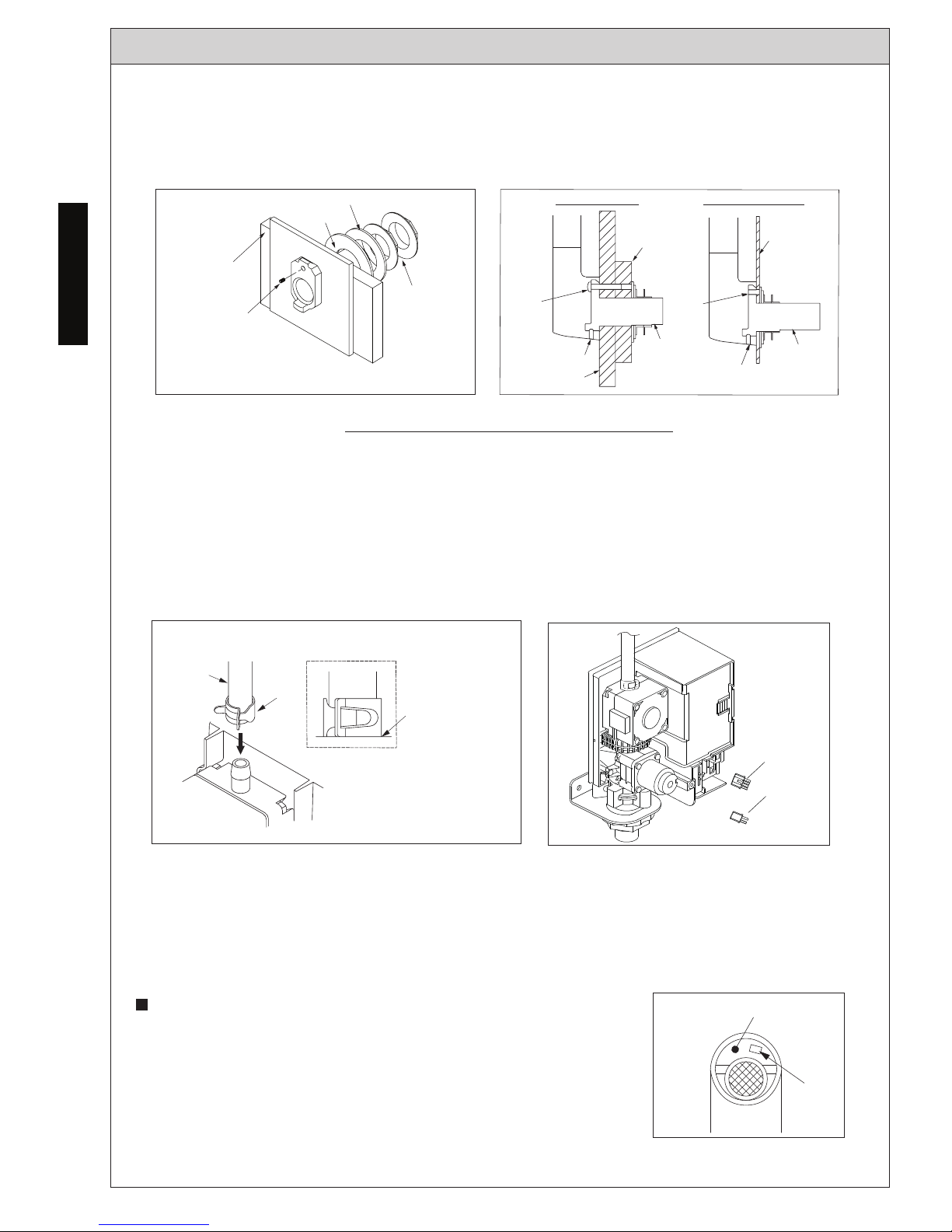
1. See the rough-in dimension page to determine the proper
location for the controller.
2. Remove the screws on the front of the controller cover and pull
to remove.
3. Mount the bracket on the wall. If necessary, use wall anchors
(see ill. 1).
4. From the top, place controller into the hole in the bracket.
From below the bracket, fasten the large nut to secure the controller (see ill. 2).
IMPORTANT!
Be sure to install controller in the correct orientation as shown. Otherwise, product will
not function properly.
5. Connect the water supply line to the inlet adapter (see ill. 3).
Page 5
To Install Helix and Libella Wall-Mounted Models (ill. 5):
NOTE: The addition of a 2 x 4” stringer behind the spout installation location is highly
recommended.
2 x 4
Stringer
2 x 4
Studs
Finished Wall
5/8” Hole for
spout
Holes for screws/
anchors
ill. 5
3. Feed the supply tube and sensor cord through
the 5/8" (16 mm) hole in center.
Place spout against wall and fasten securely with
the provided screws.
t until ekcarb eht ot noehctucse eht netsaF .4
hand-tight.
ill.6
Escutcheon
5
ENGLISH
INSTALLATION PROCEDURE
To Install Gooseneck Wall-Mounted Models (ill. 8, 9 & 10):
noitacol derised eht ta eloh )mm 92( ”8/1-1 a llirD .1
for the mounting bracket. Place the mounting
bracket
through a hole in the wall with the set
screw hole located at 12 o’clock. Mark the
location of the set screw hole on the wall and
remove the mounting bracket.
For sheet metal surface: Drill a 3/16” (5 mm) hole at the marked location.
For
a drywall/hollow wall surface: Drill a 1/4” (6.5 mm)
hole at the marked location, and install
the included wall anchors.
ill.7
Ø 1-1/8"
15/16"
Ø 3/16” (sheet metal surface)
Ø 1/4” (drywall/hollow wall)
ill. 8
Hole for set screw/machine
screw and wall
anchor
Hole for mounting bracket
To Install Helix Wall-Mounted Models (ill. 6):
3.
Place mounting bracket against wall and fasten
securely with the provided screws.
4. Pass the hose and sensor cord through the
mounting bracket, slide the spout base over the
mounting bracket and tighten the set screw to
secure the spout to the mounting bracket.
Mounting
Bracket
Set Screw
1. Place mounting template on wall at desired
location and mark all holes. Drill a 5/8" (16 mm)
diameter hole at the spout mounting location
(center) for the supply tube and sensor cord to
pass through.
2. For fastening to wood , drill three (3) pilot holes
7/64” (2.7 mm) in diameter at marked locations.
To Install Libella Wall-Mounted Models (ill. 7):
NOTE: Confirmation of wall strength is highly recommended before drilling.
For fastening to drywall or tile, drill three (3) holes
3/16” (5 mm) in diameter and insert anchors until
flush. Tap lightly with a hammer if needed.
NOTE: The addition of a 1 x 6” or plywood bracing behind the mounting location is highly
recommended for drywall/hollow wall installations. The overall maximum wall
thickness is 2” (50 mm).
NOTE: Drill bits (not supplied) for hard materials may be required.
Page 6
2. Install the mounting bracket using the rubber washer, brass washer, and both brass nuts
on back side of the installation surface. Install the included set screw (for sheet metal
installation) or 30 mm machine screw (for drywall installations).
3.
Pass the hose and sensor cord through the mounting bracket, slide the spout base over the
mounting bracket and tighten the set screw to
secure the spout to the mounting bracket.
Set Screw
(Sheet metal) or
Machine Screw
(Drywall/ Hollow
Wall)
Rubber Washer
Brass Washer
Nuts (2)
ill. 9
Plywood
(not required for sheet
metal installation)
M5x30
Machine
Screw
and
Wall
Anchor
ill. 10
Set Screw
Mounting
Bracket
M5 Set
Screw
1x6 or Plywood
Bracing
Set Screw
Sheetmetal InstallationDrywall Installation
Mounting
Bracket
Thin Wall
(Sheet
Metal
Surface)
Drywall
6
ENGLISH
INSTALLATION PROCEDURE
1.
If the spout connecting hose is too long, cut it to the appropriate length, making sure the
end is square.
2.
Push the spout connecting hose onto the outlet barb of the controller and secure it with
the hose clamp (see ill. 1). Make sure that the hose clamp is placed fully against the
controller.
NOTE: If you need to remove the hose, use
a flathead screwdriver to carefully pry
the hose from the barb.
3.
Connect the backup battery connector to the controller. It will take at least 5 minutes after
connecting the battery for the electronics to initalize. This is a normal part of startup.
Make sure there are no obstructions
between the sensor and the basin, then connect
the spout sensor connector to the
controller. (see ill. 2)
IMPORTANT!
The faucet will begin an automatic sensing range adjustment immediately after the
sensor connector is plugged into the controller. Do not place your hands or other
objects in front of the sensor.This process may take up to 20 seconds to complete.
If the sensor light continues to flash for more than 20
seconds, the spout direction will need to be readjusted
for proper operation. If adjustment is necessary, you
must do it within 10 minutes of the adjustment process
will end. To restart the process, unplug the sensor
connector for 10 seconds, then reconnect it (see ill. 3)
4. Double-check all connections, then reinstall the controller cover, securing it wit eht h
WARNING: Draw the sensor cord from the bottom of the controller while installing the
controller cover to ensure that the cord is not pinched.
Connect the Spout to the Controller
Hose
Clamp
Clamp fush
with
controller
ill. 1
Spout
Connecting
Hose
ill. 3
Sensor
Light
Sensor
ill. 2
Sensor
Connector
Battery
Connector
screws.
Page 7
7
ENGLISH
INSTALLATION PROCEDURE
Testing After Installation
Open
Close
Stop Valve
ill. 1
dna sevlav pots eht ta ylppus retaw eht no nruT
inspect all the connections for any leaks (see ill. 1).
Place hand under the sensor to activate.
For 10 sec model: water will stop after 10 seconds
while your hand is under the sensor.
Water will stop when you remove your hand.
CARE & CLEANING
PERIODIC MAINTENANCE
gninaelc nehw Do not scratch the sensor IMPORTANT!
the spout (see ill. 2).
Avoid using any cleaning materials that may scratc eht h
spout surface.
Never use polishing powder, detergent that include s
coarse particles, thinners, benzene, acids, alkaline
detergents, or nylon scrub brushes, as they can damage
the surface of the spout.
To safely clean the surface, wipe it using a dampene tfos d
cloth with diluted dishwashing detergent and dry it with
another soft cloth. If this does not adequately clean the
surface, wipe the area with a neutral detergent and wet cloth.
ill. 2
Sensor Area
Outlet
Check your faucet at least once a month for the following potential problems and to do the
following maintenance procedures:
Inspect for Leakage
Check all water connections for signs of leakage.
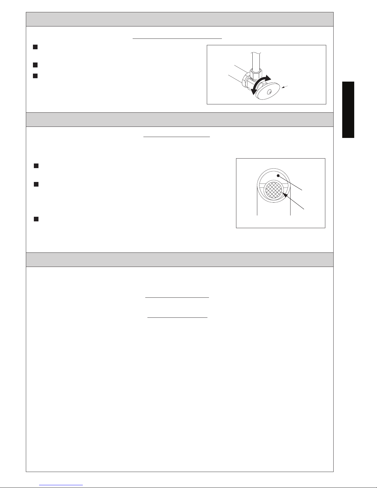
Tighten the Spout
If the spout is loose, tighten the hexagonal nut underneath the spout for deck-mounted
models.
To tighten the Helix Wall-Mounted Spout:
1. Unscrew the escutcheon, tighten the three screws securing the mounting bracket to the
wall.
2. Reinstall escutcheon.
To tighten the Gooseneck Wall-Mounted Spout
1. Turn off the water supply at the stop valves.
2. Disconnect the spout connecting hose and sensor connector
from the controller.
3. Remove the spout from the mounting bracket by removing the set screw on the bottom
of the spout base.
4. Tighten the set screw on the back of the spout, then reinstall the spout on the mounting
bracket.
5. As required, ensure the set screw on the mounting bracket and mounting nuts behind
the sink/wall (refer to “Install the Spout” section) are tight.
For 20 sec model: water will stop after 20 seconds.
Spout and Sensor
Page 8
8
ENGLISH
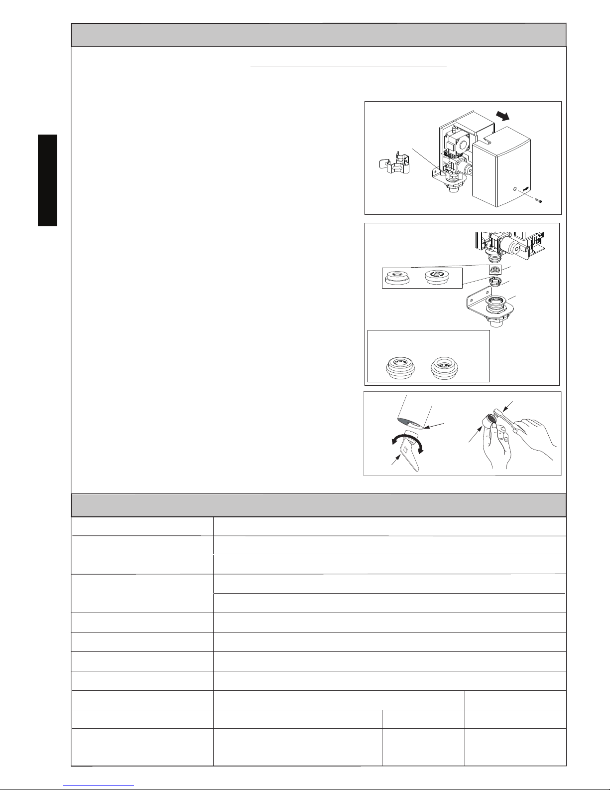
When the inlet screen is clogged, the flow rate will decrease. Decreased flow rate can
lead to insufficient power generation, which will deplete the backup battery prematurely.
Cleaning the screen (see ill. 1 & 2):
1. Turn the water off at the stop valves.
2. Remove controller cover and quick fastener.
3. Remove controller from hose adapter.
.hsurb a htiw ti naelc dna neercs evomeR .4
5. Reinstall the cleaned screen.
IMPORTANT!
If flow regulator (or flow regulator assembly
for TELC103-###E) falls out, reinstall it in the
correct orientation (O-ring side facing screen)
as shown. Otherwise, product will not
function properly.
6. Reinstall the controller into the hose adapter
until fully seated, and secure it with the
quick fastener.
7. Reinstall cover, securing it with the screws.
8. Open stop valves and check all connections.
Cleaning the nozzle (see ill. 3):
1. Remove the nozzle from the spout
with the supplied tool.
2. Clean the nozzle with a soft brush
to remove any dirt from the screen.
3. Re-install the nozzle in the spout.
Power supply
Hydropower Generation (self-powering power supply)
Sensor Detection Range
5-1/8”~ 7-7/8” (130 ~ 200mm)
Sensor is self-adjusting.
Water Supply Connection
Minimum : 15 psi (100 kPa) (Flowing)
Maximum : 80 psi (551 kPa)
Water Supply Pressure
G1/2 compatible with ½ NPSM
39 ~ 110°F (4 ~ 43.3°C)
Inlet Temperature range
Ambient Temperature
32 ~ 104°F (0 ~ 40°C)
Humidity
Max. 90% RH
0.09 gpc
(0.36 Lpc)
0.18 gpc
(0.67 Lpc)
0.19 gpc
(0.72 Lpc)
Flow Rate
Duration
10 seconds 20 seconds
SPECIFICATIONS
PERIODIC MAINTENANCE
Cleaning the Inlet Screen and Nozzle
Volume per cycle
1.0 gpm 0.5 gpm 0.35 gpm
10 seconds 20 seconds
0.11 gpc
(0.44 Lpc)
Open
Close
Spout
Nozzle
Key
ill. 3
Spout
Nozzle
Brush
ill. 1
Screen
Flow Regulator
Remove Quick Fastener
Hose Adapter
ill. 2
Flow regulator for TELC103-###E
models is assembled inside an adapter.
Install assembly with correct orientation.
Page 9
9
ENGLISH
Problem Cause Solution
Water won’t
begin run-
ning.
The surface of the sensor is dirty. Clean the surface of the sensor.
There is an obstruction in front of
the sensor.
Remove the obstruction.
The stop valve is turned off. Turn on the valve.
Backup battery connector is discon -
nected.
Connect the backup battery connector.
The power generator and sensor
connector is disconnected.
Securely attach the connector(s).
Water supply is suspended. Wait until the water supply is
restored.
The strainer or the regulating screen
is clogged.
Clean the strainer and the regulating
screen.
Water won’t
stop
running.
The surface of the sensor is dirty. Clean the surface of the sensor.
There is an obstruction in front of
the sensor.
Remove the obstruction.
If the water continues to run after attempting the above solutions, turn
off the stop valve.
Low flow
rate.
The stop valve is not fully opened. Open the stop valve fully.
The strainer or the regulating screen
is clogged.
Clean the strainer and the regulating
screen.
Water tem-
perature is
too high.
The temperature control handle is
set at “H”.
Set the temperature control
handle to the middle point.
The stop valve connected to the
cold-water supply is not fully
opened.
Open the cold-water stop valve fully.
Water tem-
perature is
too low.
The temperature control handle is
set at “C”.
Set the temperature control
handle to the middle point.
The stop valve connected to the hot
water supply is not fully opened.
Open the hot water stop valve fully.
The hot water supply temperature is
lower than 120°F.
Set the hot water supply temperature
to 120° F.
Water
tempera-
ture is not
controlled
properly.
One side of the stop valve is not
fully opened.
Open the stop valve fully.
The strainer or the regulating screen
is clogged.
Clean the strainer and the regulating
screen.
Short detec-
tion range.
The self-adjusting sensor may not
work properly when strained or
blocked by water droplets.
Clean the sensor surface.
TROUBLESHOOTING
Page 10
10
ENGLISH
WARRANTY
1. TOTO ® warrants its electronic flush valves, faucets and soap dispensers (“Product”) to be free from defects in
materials and workmanship during normal use when properly installed and serviced, for a period of three (3) years
from date of purchase. This limited warranty is extended only to the ORIGINAL PURCHASER of the Product and is
not transferable to any third party, including but not limited to any subsequent purchaser or owner of the Product.
This warranty applies only to TOTO Product purchased and installed in North, Central and South America.
2. TOTO’s obligations under this warranty are limited to repair, replacement or other appropriate adjustment, at
TOTO’s option, of the Product or parts found to be defective in normal use, provided that such Product was properly
sa snoitcepsni hcus ekam ot thgir eht sevreser OTOT .snoitcurtsni htiw ecnadrocca ni decivres dna desu ,dellatsni
ni strap ro robal rof egrahc ton lliw OTOT .tcefed eht fo esuac eht enimreted ot redro ni yrassecen eb yam
connection with warranty repairs or replacements. TOTO is not responsible for the cost of removal, return and/or
reinstallation of the Product.
4. In order for this limited warranty to be valid, proof of purchase is required. TOTO encourages warranty registration
upon purchase to create a record of Product ownership at http://www.se is required. TOTO encourages warranty
registration upon and failure to register will not diminish your limited warranty rights.
5. THIS WARRANTY GIVES YOU SPECIFIC LEGAL RIGHTS. YOU MAY HAVE OTHER RIGHTS WHICH VARY
FROM STATE TO STATE, PROVINCE TO PROVINCE OR COUNTRY TO COUNTRY.
6. To obtain warranty repair service under this warranty, you must take the Product or deliver it prepaid to a TOTO
service facility together with proof of purchase (original sales receipt) and a letter stating the problem, or contact
a TOTO distributor or products service contractor, or write directly to TOTO U.S.A., INC., 1155 Southern Road,
Morrow, GA 30260 (888) 295 8134 or (678) 466-1300, if outside the U.S.A. If, because of the size of the Product
or nature of the defect, the Product cannot be returned to TOTO, receipt by TOTO of written notice of the defect
esoohc yam OTOT ,esac hcus nI .yreviled etutitsnoc llahs )tpiecer selas lanigiro( esahcrup fo foorp htiw rehtegot
to repair the Product at the purchaser’s location or pay to transport the Product to a service facility.
THIS WRITTEN WARRANTY IS THE ONLY WARRANTY MADE BY TOTO. REPAIR, REPLACEMENT OR OTHER APPROPRIATE
ADJUSTMENT AS PROVIDED UNDER THIS WARRANTY SHALL BE THE EXCLUSIVE REMEDY AVAILABLE TO THE ORIGINAL
PURCHASER. TOTO SHALL NOT BE RESPONSIBLE FOR LOSS OF THE PRODUCT OR FOR OTHER INCIDENTAL, SPECIAL
OR CONSEQUENTIAL DAMAGES OR EXPENSES INCURRED BY THE ORIGINAL PURCHASER, OR FOR LABOR OR OTHER
COSTS DUE TO INSTALLATION OR REMOVAL, OR COSTS OF REPAIRS BY OTHERS, OR FOR ANY OTHER EXPENSE NOT
SPECIFICALLY STATED ABOVE. IN NO EVENT WILL TOTO’S RESPONSIBILITY EXCEED THE PURCHASE PRICE OF THE
PRODUCT. EXCEPT TO THE EXTENT PROHIBITED BY APPLICABLE LAW, ANY IMPLIED WARRANTIES, INCLUDING THAT
OF MERCHANTABILITY OR FITNESS FOR USE OR FOR A PARTICULAR PURPOSE, ARE EXPRESSLY DISCLAIMED. SOME
STATES DO NOT ALLOW LIMITATIONS ON HOW LONG AN IMPLIED WARRANTY LASTS, OR THE EXCLUSION OR
LIMITATION OF INCIDENTAL OR CONSEQUENTIAL DAMAGES, SO THE ABOVE LIMITATION AND EXCLUSION MAY NOT
APPLY TO YOU.
3. This warranty does not apply to the following items:
a. Damage or loss sustained in a natural calamity such as fire, earthquake, flood, thunder, electrical storm, etc.
b. Damage or loss resulting from any accident, unreasonable use, misuse, abuse, negligence, or improper
care, cleaning, or maintenance of the Product.
c. Damage or loss resulting from sediments or foreign matter contained in a liquid soap system.
ro/dna hsrah a ni tcudorP eht fo noitallatsni morf ro noitallatsni reporpmi morf gnitluser ssol ro egamaD .d
hazardous environment, or improper removal, repair or modification of the Product.
e. Damage or loss resulting from electrical surges or lightning strikes or other acts which are not the fault of
TOTO or which the Product is not specified to tolerate.
f. Damage or loss resulting from normal and customary wear and tear, such as gloss reduction, scratching or
fading over time due to use, cleaning practices or water or atmospheric conditions, including but not limited
to, the use of bleach, alkali, acid cleaners, dry (powder) cleaners or any other abrasive cleaners or the use
of metal or nylon scrubbers.
Page 11
11
L O Ñ A P S E
ÍNDICE
GRACIAS POR ELEGIR TOTO!
INCLUÍA PARTE
La misión de TOTO es dar al mundo estilos de vida más saludables, higiénicos y cómodos.
Diseñamos cada producto guiándonos por el principio del equilibrio entre forma y función.
Felicitaciones por su elección.
Asegúrese que todas estas partes estén incluidas en su empacado*:
(La apariencia de algunos componentes puede variar dependiendo del modelo)
CONTROLADOR
SURTIDOR
STD
TELS10*
Gooseneck-Wall
Helix-Wall
TELS13*
Helix
TELS11* TELS16*
Helix-M
TELS12*
Axiom
TELS14*
Gooseneck
TELS15*
UP
UP
Libella Wall Libella-M Wall
TELS1C* TELS1D* TELS1A* TELS1B*
Libella Libella-M
¡Gracias Por Elegir TOTO! ..................
11
Incluía Parte............................................ 11
Precaución............................................... 12
Antes de la Instalación........................... 12
12
Cuidado y Limpieza....................................... 16
Mantenimiento Periódico......................... ..... 16
Especificacione...............................................17
Resolución de Problemas.............................. 18
Garantía .......................................................... 19
Bosquejo......................................................... 38
Procedimiento de Instalación............... 13
Inicializando el Producto EcoPower......
Page 12
12
PRECAUCIÓN
ANTES DE LA INSTALACIÓN
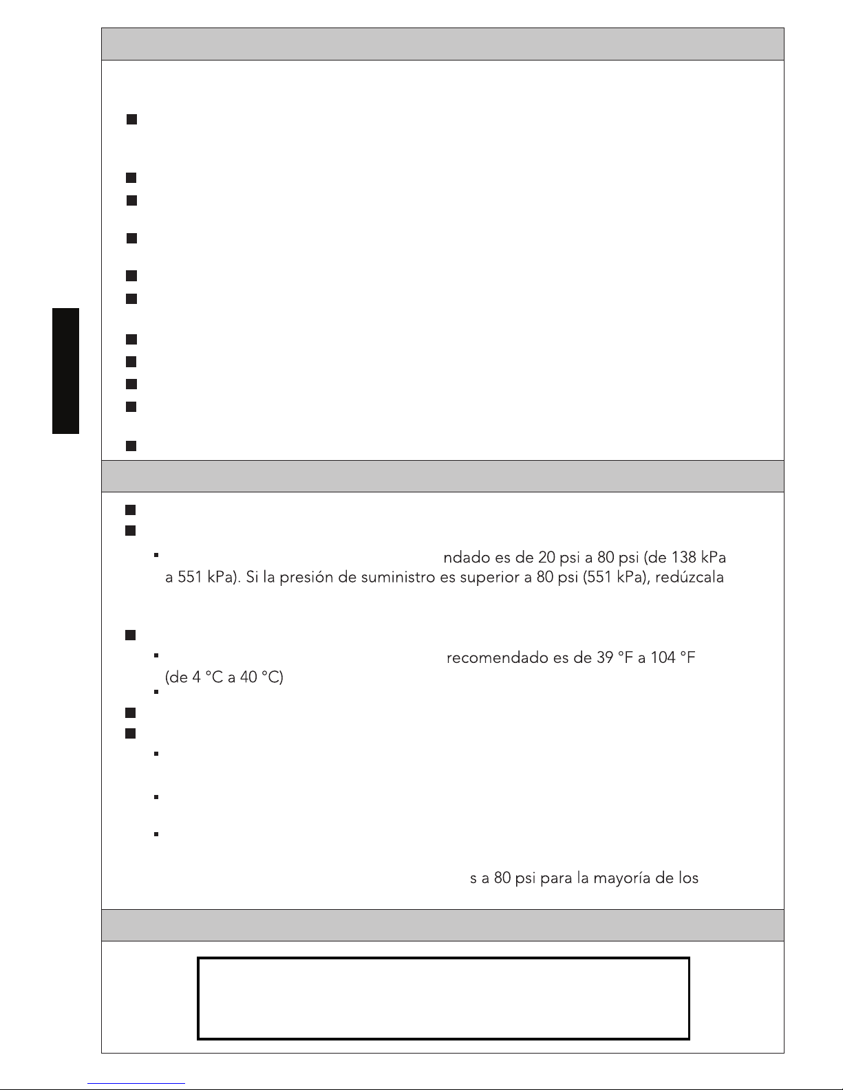
Siga todos los códigos locales de plomería y construcción.
Verifique la presión de suministro de agua fría y/o caliente.
El rango de presión de trabajo recome
hasta alcanzar el rango recomendado usando una válvula de reducción de la
presión (se vende por separado).
Verifique la temperatura del suministro de agua.
El rango de temperatura de suministro
Nunca utilice vapor como un suministro de agua caliente.
Descargue todas las líneas de agua antes de su instalación.
Otras precauciones antes de comenzar:
Ponga especial atención para que la superficie del sensor no se dañe o raye
durante el proceso de instalación.
Asegúrese que toda la tubería, válvulas de paso y líneas de conexión
estén instaladas de acuerdo con los códigos locales.
No coloque otros dispositivos que utilicen un inversor o sensor infrarrojo cerca
del grifo, ya que puede causar un malfuncionamiento del grifo.
No se recomiendan presiones de agua superiore
accesorios de fontanería. Consulte su código de fontanería local para obtener detalles.
Lea las siguientes notas y sígalas siempre. De lo contrario, podría resultar herido y/o
causar daños materiales.
Ninguna persona que no sea un ingeniero de servicios debe desensamblar, reparar
o modificar este grifo, a menos que se describa específicamente en este manual.
No hacer lo anterior puede resultar en un malfuncionamiento del producto.
Fije las temperaturas del grifo únicamente a las permitidas en sus códigos locales.
No utilice este grifo en una ubicación húmeda donde se pueda acumular agua
corriente o condensación en la superficie, especialmente en un sauna o vapor.
No golpee o patee el grifo o la caja del controlador, ya que puede dañar la unidad
o causar fugas.
Desconecte el conector de la batería de respaldo cuando el grifo no esté en uso por
un largo periodo de tiempo.
Siempre cierre la(s) válvula(s) de paso al limpiar el filtro.
Revise periódicamente la tubería para verificar que no haya fugas.
Si la temperatura ambiente cae drásticamente, envuelva la tubería con aislante.
Asegúrese de que el cable de energía no entre en contacto con la tubería de
suministro de agua caliente.
Evite colocar cualquier objeto dentro del rango de detección del sensor infrarrojo.
INICIALIZANDO EL PRODUCTO ECOPOWER
No toque la superficie caliente de la llave de paso, ya que puede estar muy caliente.
ESPAÑOL
Tenga en cuenta que tardará al menos 5 minutos
después de conectar la batería para que la electrónica se inialice.
(Consulte la página 6 para ver las ilustraciones.)
Page 13

13
PROCEDIMIENTO DE INSTALACIÓN
NOTA: Antes de instalar el producto, asegúrese de descargar perfectamente las tuberías de
suministro de suciedad y desechos. Cierre el suministro de agua en las llaves de
paso después de descargarlas.
Para Instalar Modelos Montados en el Mostrador
(vea la ilust. 4):
Asegure el surtidor a la parte superior del mostrador
con el soporte incluido y la tuerca hexagonal.
Asegúrese de que el surtidor sea montado con la
punta apuntando hacia el centro del lavabo.
Instale el Controlador
Instale el Surtidor
SURTIDOR
ill. 4
1. Vea la página de dimensiones en borrador para determinar
la ubicación adecuada para el controlador.
2. Retire los tornillos en la parte de enfrente de la cubierta del
controlador y jale para retirarla.
3. Monte el soporte sobre la pared. De ser necesario, use anclajes
de pared (vea la ilust. 1).
4. Desde la parte superior, coloque el controlador en el orificio, en el soporte. Desde la
parte inferior del soporte, ajuste la tuerca grande para fijar el controlador (vea la ilust. 2).
IMPORTANTE!
Asegúrese de instalar el controlador en la orientación correcta, como se muestra.
De lo contrario, el producto no funcionará correctamente.
5. Conecte la línea de suministro de agua al adaptador de entrada (vea la ilust. 3).
NOTA: Si usa una válvula termostática (se vende por separado), consulte su manual de
instalación para obtener detalles.
ill. 2
ill. 3
La tuerca
Manguera flexible
del surtidor
Cable del sensor
Empaque
Retenedor
del surtidor
El soporte
La tuerca
Llave de paso
Las mangueras
de suministro.
El soporte
La tuerca
ill.1
ESPAÑOL
Page 14

14
ESPAÑOL
PROCEDIMIENTO DE INSTALACIÓN
2. Para ajustar a una superficie de madera,
perfore tres (3) orificios piloto con un
diámetro de 7/64 in (2,7 mm) en las ubicaciones marcadas.
Para ajustar a una pared laminada o azulejo, perfore tres (3) orificios con un diámetro de
3/16 in (5 mm) e inserte los anclajes hasta que estén a ras. Dé golpes suaves con un
martillo si es necesario.
3. Alimente el tubo de suministro y el cable
e
salida contra la pared y ajústelo firmem
-ente con los tornillos proporcionados.
Para Instalar los Modelos Montados en Pared Cuello de Ganso (ill. 8, 9& 10):
NOTA: La adición de un contrachapado de recubrimiento de 1 x 6” detrás de la ubicación
de montaje es altamente recomendable para las instalaciones en pared laminada/
pared
hueca. El grosor de pared máximo total es de 2” (50 mm).
1.
Perfore un orificio de 1-1/8” (29 mm) en
la ubicación deseada para el soporte de
montaje. Ponga el soporte de montaje a
través de un orificio en la pared con el
orificio del tornillo de fijación ubicado a
las 12 en punto. Marque la ubicación del
orificio del tornillo de fijación en la pared y retire el soporte de montaje.
Para una superficie de hoja de metal: Perfor
e un orificio de 3/16” (5 mm) en la ubicación marcada.
NOTA: Se pueden necesitar brocas de taladro (no proporcionadas) para materiales duros.
Para una superficie de pared laminada/pared hueca: Perfore un orificio de 1/4”(6.5 mm) en
la ubicación marcada e instale los taquetes incluidos.
NOTA: Es altamente recomendable la confirmación de la resistencia de la pared antes de perforar.
STEP 8
2 x 4
Marco de
2 x 4
Montantes
Pared Terminada
Orificio de 3/4” de
Diámetro para Taquetes
Orificio de 3/16” de
Diámetro para Taquetes
ill. 5
ill.6
Escudete
Ø 1-1/8"
15/16"
Ø 3/16” (Superficie de la hoja metálica)
Ø 1/4” (superficie de pared laminada/
pared hueca)
ill. 8
Orificio para el tornillo de fijación/
tornillo de máquina
y anclaije de pared
Orificio para el surtidor al
soporte de montaje
Para Instalar Modelos Montados en la Pared de Helix y Libella (ill. 5)
NOTA: La adición de un marco de 2 x 6” detrás de la ubicación de la instalación del
surtidor es altamente recomendable.
1. Coloque la plantilla de montaje sobre
lapared en la ubicación deseada y marque
todos los orificios. Perfore un orificio con
un diámetro de 5/8 in (16 mm) en la
ubicación del montaje del tubo de salida
(centro) para que pasen el tubo de suministro
y el cable del sensor.
ill.7
Retenedor
del surtidor
Tornillo de Fijación
4. Ajuste manualmente el escudete al soporte.
3. Coloque el soporte de montaje contra la
pared y fíjelo firmemente con los tornillos
que se incluyen.
4. Pase la cuerda del sensor y la manguera a
través del soporte de montaje, deslice la
base de la boquilla de escape sobre el
soporte de montaje y apriete el tornillo de
fijación para fijar la boquilla de escape en
el soporte de montaje.
Para Instalar Modelos Montados en la Pared de Libella (ill. 7)
Para Instalar Modelos Montados en la Pared de Helix (ill. 6)
Page 15

15
Ñ A P S E
PROCEDIMIENTO DE INSTALACIÓN
1. Si la manguera que conecta el surtidor es demasiado larga, córtela a la longitud
adecuada, asegurándose que el extremo esté cuadrado.
2. Empuje la manguera que conecta el surtidor en la lengüeta de salida del controla
-dor y asegúrela con la abrazadera de la manguera (ver iII.1). Asegúrese que la
abrazadera de la manguera esté perfectamente colocada contra el controlador.
3. Conecte el conector de la batería de respaldo al controlador. Se tardará al menos
obstrucciones entre el sensor y el lavabo, después conecte el conector del sensor
del surtidor al controlador (ver iII. 2).
IMPORTANTE!
de que el conector del sensor esté enchufado al controlador
No coloque las manos ni
otros objetos frente al sensor.Completar este proceso puede llevar hasta 20 segundos.
,sodnuges 02 ed sám rop odnaedaprap eugis rosnes led zul al iS
se deberá reajustar la dirección del surtidor para una operación
adecuada. Si el ajuste es necesario, debe hacerlo dentro de los
siguientes 10 minutos o el proceso de ajuste terminará. Para
reiniciar el proceso, eso, desconecte el conector del sensor 10
segundos y vuélvalo a conectar (ver iII. 3).
4. Vuelva a revisar todas las conexiones, después reinstale la
cubierta del controlador, asegurándola con los tornillos.
ADVERTENCIA: Lleve el cable del sensor a la parte inferior del controlador mientras instala
la cubierta del controlador para asegurarse que el cable no quede atrapado.
Conecte el Surtidor al Controlador
2. Instale el soporte de montaje utilizando una arandela de hule, arandela de latón y
ambas tuercas de latón en la parte posterior de la superficie de instalación. Instale
el tornillo de fijación incluido (para la instalación en hoja metálica) ó tornillo de
máquina de 30 mm (para instalaciones en pared laminada).
3. Pase la manguera y el cable del sensor a través del soporte de montaje, deslice la
base del surtidor sobre el soporte de montaje y apriete el tornillo de fijación para
asegurar el surtidor al soporte de montaje.
Tornillo de Fijación
(Hoja Metálica) or Tornillo
de Máquina (pared
laminada/pared hueca)
Arandela de
goma
Arandela de Latón
La tuerca (2)
ill. 9
Contrachapado
(no se requiere para la
instalación en hoja
metálica)
M5x30
Tornillo de
Máquina y
Taquetes
ill. 10
Tornillo de Fijación
Retenedor
del surtidor
M5 Tornillo
de Fijación
1x6 o Contrachapado
de Recubrimiento
Tornillo de
Fijación
Instalación en Hoja MetálicaInstalación en Pared Laminada
Retenedor
del surtidor
Pared Delgada
(Superficie de la
Hoja Metálica)
Pared Laminada
Abrazadera
de la manguera
Abrazadera a
ras con
controlador
ill. 1
Manguera
flexible
del surtidor
ill. 2
Conector
del Sensor
ill. 3
Luz del
Sensor
Sensor
El grifo comenzará un ajuste de rango de detección automático inmediatamente después
Conector de
la batería
NOTA:
Si necesita quitar la manguera, utilice
un destornillador de cabeza plana para
sacar cuidadosamente la manguera
de la lengüeta.
5 minutos después de conectar la batería para que la electrónica se inicialice.
Esta es una parte normal de la puesta en marcha. Asegúrese que no haya
ESPAÑOL
Page 16

16
PROCEDIMIENTO DE INSTALACIÓN
Prueba después de la instalación
Abrir
Cerrar
Llave de paso
ill. 1
Encienda el suministro de agua en las llaves de
paso e inspeccione todas as conexiones
para verificar que no haya fugas (ver iII. 1).
Coloque la mano debajo del sensor para activar.
Para el modelo de 10 seg.: el agua se detendrá
después de 10 segundos mientras la mano está
debajo del sensor. El agua sedetendrá cuando retire la mano.
Para el modelo de 20 seg.: el agua se detendrá después de 20 segundos.
CUIDADO Y LIMPIEZA
MANTENIMIENTO PERIÓDICO
Surtidor y Sensor
IMPORTANTE!
No raye el sensor al limpiar el surtidor (ver iII. 2).
Evite utilizar cualquier material de limpieza que pueda
rayar la superficie del surtidor.
Nunca utilice polvo para pulir, detergente que incluya
partículas corrosivas, thinners, benceno, ácidos,
detergentes alcalinos ni estropajos de nylon, ya que
pueden dañar la superficie del surtidor.
Para limpiar la superficie con seguridad, límpiela con un trapo remojado en detergente
para trastes diluido y séquelo con otro trapo. Si esto no limpia adecuadamente la
superficie, límpiela conun detergente neutro y un trapo mojado.
ill. 2
Sensor
Boquilla del surtidor
Revise su grifo al menos una vez al mes para los siguientes problemas potenciales y para
realizar los siguientes procedimientos de mantenimiento:
Inspeccione para ver si hay Fugas
Revise todas las conexiones de agua para ver si hay signos de fugas.
Apriete el Surtidor
Si el surtidor está flojo, apriete la tuerca hexagonal debajo del surtidor para los modelos
montados en el mostrador.
Para apretar el Surtidor Montado en la Pared de Helix:
1. Desatornille el escudete, apriete los tres ornillos que aseguran el soporte de montaje
a la pared y los tres tornillos que aseguran el surtidor al soporte de montaje.
.eteducse le elatsnieR .2
Para apretar el Surtidor Montado en la Pared Cuello de Ganso:
1. Cierre el suministro de agua en las llaves de paso.
2. Desconecte la manguera flexible del surtidor y conector del sensor.
3. Retire el surtidor del soporte de montaje qu itando el tornillo de fijación en la parte
inferior de la base del surtidor.
4. Apriete el tornillo de fijación en la parte posterior del surtidor, después reinstale el
surtidor en el soporte de montaje.
5 Según se requiera, asegure el tornillo de fijación en el soporte de montaje y las tuercas
de fijación detrás del lavabo/pared (consulte la sección “Instale el surtidor”) están
apretadas.
LOÑAPSE
Page 17

17
ESPAÑOL
Limpiando el Filtro de Entrada y la Boquilla
Cuando el filtro de entrada esté tapado, la velocidad de flujo disminuirá. Una disminución
en la velocidad del flujo puede llevar a una generación de energía insuficiente, que la
batería de respaldo rápidamente.
Para limpiar el filtro (ver iII. 1):
1. Cierre el agua en las válvulas de suspensión.
2. Retire la tapa y luego retire el sujetador rápido.
3. Retire el controlador.
4. Retire el filtro y límpielo con un cepillo.
IMPORTANTE!
Si regulador del flujo (o montaje de regulador del
flujo para TELC103-###E) se cae, vuelva a instalarlo
en la orientación correcta como se muestra (anillo
en O hacia filtro).
De lo contrario el producto
6. Vuelva a instalar el controlador en el adaptador
hasta que esté completamente asentado, y
asegúrelo con el fijador rápido.
7. Vuelva a instalar la cubierta, asegurándola
con los tornillos.
8. Abra la tapa angular y verifique todas las
conexiones.
Para limpiar la boquilla (ver iII. 2):
1. Retire la boquilla del surtidor con la
herramienta proporcionada.
2. Limpie la boquilla con un cepillo suave
para retirar toda la suciedad de la pantalla.
3.
Reinstale la boquilla en el surtidor.
ESPECIFICACIONES
Abrir
Cerrar
Boquilla
del Surtidor
Llave
Boquilla
del Surtidor
Cepillo
Filtro
Regulador
del flujo
Suministro de energía
Generación de Hidroenergía
Rango de detección
del sensor
5-1/8’”~ 7-7/8” (130~200mm)
El sensor tiene ajuste automático.
Presión del suministro
Mínima requerida: 15 psi (100 kPa) (fluyendo)
Máxima: 80 psi (551 kPa)
Conexión del suministro
G1/2
39 ~ 110°F (4 ~ 43.3°C)
Temperaturas de entrada
Temperaturas ambiente
32 ~ 104°F (0 ~ 40°C)
Humedad
Max. 90% RH
Velocidad del flujo
Duración
MANTENIMIENTO PERIÓDICO
0.09 gpc
(0.36 Lpc)
0.18 gpc
(0.67 Lpc)
0.19 gpc
(0.72 Lpc)
10 segundos 20 segundos
1.0 gpm 0.5 gpm 0.35 gpm
10 segundos 20 segundos
0.11 gpc
(0.44 Lpc)
Volumen por ciclo
ill. 3
ill. 1
Retire fijador rápido
Adaptador de
tubo
ill. 2
Reguladores de flujo para el modelo TELC103-###E
se montan dentro de un adaptador.
Instale el conjunto con la orientación correcta.
5. Vuelva a instalar el filtro limpio.
funcionará mal.
Page 18

18
ESPAÑOL
Problema Causa Solución
La superficie del sensor está sucia. Limpie la superficie del sensor.
Hay una obstrucción enfrente del
sensor.
Retire la obstrucción.
La válvula de suspensión está
apagada.
Abra la válvula.
El conector de la batería de respaldo
está desconectada.
Conecte el conector de la batería de
respaldo.
El generador de energía y el conector
del sensor están desconectados.
Fije perfectamente el (los)
conector(es).
El suministro de agua está
suspendido.
Espere a que el suministro de agua
se restablezca.
El filtro o la pantalla reguladora está
tapado.
Limpie el filtro y la pantalla reguladora.
El agua
no sigue
corriendo.
La superficie del sensor está sucia. Limpie la superficie del sensor.
Hay una obstrucción enfrente del
sensor.
Retire la obstrucción.
Si el agua continúa corriendo después de intentar las soluciones
anteriores, cierre la válvula de suspensión.
Velocidad del
flujo baja.
La válvula de suspensión no está
completamente abierta.
Abra la válvula de suspensión
completamente.
El filtro o la pantalla reguladora está
tapado.
Limpie el filtro y la pantalla
reguladora.
La tempera-
tura del agua
es demasia do
alta.
La manija del control de temperatura
está fija en “H”.
Fije la manija del control de
temperatura en el punto medio.
La válvula de suspensión conectada
al suministro de agua fría no está
completamente abierta.
Abra la válvula de suspensión de agua
fría completamente.
La tempera-
atura del agua
es demasiado
baja.
La manija del control de temperatura
está fija en “C”.
Fije la manija del control de
temperatura en el punto medio.
La válvula de suspensión conectada a
l suministro de agua caliente no está
completamente abierta.
Abra la válvula de suspensión de
agua caliente completamente.
La temperatura del suministro de
agua caliente es menor a 120F.
Fije la temperatura del suministro de
agua caliente en 120F.
La tempera-
atura del agua
no está contr-
olada adecua-
damente.
Un lado de la válvula de suspensión
no está completamente abierto.
Abra la válvula de suspensión
completamente.
El filtro o la pantalla reguladora
está tapado.
Limpie el filtro y la pantalla
reguladora.
Rango de det-
ección corto.
El sensor de ajuste automático puede
no funcionar adecuadamente cuando
está tapado o bloqueado por gotitas
de agua.
Limpie la superficie del sensor.
RESOLUCIÓN DE PROBLEMAS
El agua no
empieza a
correr.
Page 19

19
ESPAÑOL
Garantía
1. TOTO ®garantiza que sus válvulas de descarga electrónica, grifos y dispensadores de jabón (“Producto”) están
libres de defectos en los materiales y mano de obra durante el uso normal cuando se instala y se mantiene de
manera adecuada, por un período de tres (3) años a partir de la fecha de adquisición. Esta garantía limitada se
extiende solamente al COMPRADOR ORIGINAL del Producto y no es transferible a terceros, incluyendo pero no
taxativamente cualquier comprador o propietario subsecuente del Producto. Esta garantía se aplica solamente al
producto TOTO adquirido e instalado en América del Norte, Central y Sur.
2. Las obligaciones de TOTO conforme a esta garantía se limitan a la reparación, reemplazo u otro ajuste apropiado,
a discreción de TOTO, del Producto o las piezas que resulten defectuosas en su uso normal, siempre que dicho
Producto fuera instalado, utilizado y mantenido adecuadamente en consonancia a las instrucciones. TOTO se
reserva el derecho de realizar tantas inspecciones como sean necesarias para determinar la causa del defecto.
TOTO no cobrará por la mano de obra o piezas con respecto a las reparaciones o reemplazos de la garantía.
TOTO no es responsable del costo de la retirada, devolución o reinstalación del Producto.
4. Para que esta garantía limitada sea válida, se requiere el comprobante de compra. Se requiere que TOTO exija el
registro de garantía en la compra para crear un registro de propiedad del Producto en http://www.se. TOTO exige
el registro de la garantía y si no se registra no se reducirán sus derechos de garantía limitada.
5. ESTA GARANTÍA LE OTORGA DERECHOS LEGALES ESPECÍFICOS. PUEDE TENER OTROS DERECHOS
QUE VARÍAN ENTRE ESTADOS, PROVINCIAS O PAÍSES.
6. A fin de obtener el servicio de reparación de la garantía en virtud de esta garantía, deberá llevar el producto o
entregarlo prepago a un servicio técnico de TOTO junto con el comprobante de compra (recibo de venta original) y
una carta que indique el problema, o póngase en contacto con un distribuidor o contratista de servicio de productos
de TOTO o bien escriba directamente a TOTO U.S.A., INC., 1155 Southern Road, Morrow, GA 30260 (888) 295
8134 o (678) 466-1300, si no se encuentra en los Estados Unidos. Si, debido al tamaño del Producto o a la
naturaleza del defecto, el Producto no se puede devolver a TOTO, el recibo de TOTO del aviso por escrito del
defecto junto con el comprobante de compra (recibo de venta original) constituirá la entrega. En tal caso, TOTO
puede optar por reparar el Producto en el lugar del comprador o pagar para transportar el Producto a un servicio
técnico.
ESTA GARANTÍA POR ESCRITO ES LA ÚNICA GARANTÍA REALIZADA POR TOTO. LA REPARACIÓN, REEMPLAZO U OTRO
AJUSTE ADECUADO, TAL COMO APARECE EN ESTA GARANTÍA SERÁ EL ÚNICO RECURSO DISPONIBLE PARA EL
COMPRADOR ORIGINAL. TOTO NO SERÁ RESPONSABLE DE LA PÉRDIDA DEL PRODUCTO O DE OTROS DAÑOS
INCIDENTALES, ESPECIALES O CONSECUENCIALES O GASTOS INCURRIDOS POR EL COMPRADOR ORIGINAL, O DE LA
MANO DE OBRA U OTROS COSTOS RELACIONADOS CON LA INSTALACIÓN O RETIRADA, O COSTOS DE REPARACIONES
REALIZADOS POR OTROS O DE NINGÚN OTRO GASTO QUE NO SE HUBIERA ESPECIFICADO ANTERIORMENTE. EN
NINGÚN CASO LA RESPONSABILIDAD DE TOTO EXCEDERÁ EL PRECIO DE COMPRA DEL PRODUCTO. SALVO
DISPOSICIÓN LEGAL CONTRARIA, TODA GARANTÍA IMPLÍCITA, QUE INCLUYE LA DE COMERCIABILIDAD O IDONEIDAD
PARA USO O PARA UN PROPÓSITO PARTICULAR, ESTÁ EXPRESAMENTE PROHIBIDA. ALGUNOS ESTADOS NO
PERMITEN LIMITACIONES SOBRE LA DURACIÓN DE UNA GARANTÍA IMPLÍCITA, O LA EXCLUSIÓN O LIMITACIÓN DE
DAÑOS INCIDENTALES O CONSECUENTES, POR ESO LA LIMITACIÓN Y EXCLUSIÓN ANTERIORES PUEDEN NO
APLICARSE EN ESTE CASO.
3. Esta garantía no se aplica a los siguientes puntos:
a. Daños o pérdidas resultantes de una calamidad natural como incendio, terremoto, inundación, truenos,
tormenta eléctrica, etc.
b. Daños o pérdidas resultantes de cualquier accidente, uso irrazonable, uso indebido, abuso, negligencia, o
cuidado inadecuado, limpieza o mantenimiento del Producto.
c. Daños o pérdidas resultantes de los sedimentos o cuerpos extraños en un sistema de jabón líquido.
d.
Daños o pérdidas resultantes de una instalación incorrecta o de la instalación del Producto en un ambiente
áspero o peligroso, o retirada, reparación o modificación inadecuada del Producto.
e. Daños o pérdidas resultantes de sobrecargas eléctricas o rayos u otros actos que no sean responsabilidad
de TOTO o que el Producto no es especificado para tolerar.
f.
Daños o pérdidas resultantes del desgaste normal y habitual, como pérdida de brillo, rayado o desvanecimiento
con el tiempo debido al uso, prácticas de limpieza, condiciones atmosféricas o agua, incluyendo
pero no taxativamente, el uso de lejía, alcalinos, limpiadores ácidos, limpiadores secos (polvo) o
limpiadores abrasivos o el uso de depuradores de metal o nylon.
Page 20

20
SIAÇNARF
TABLE DES MATIÈRES
MERCI D’AVOIR CHOISI TOTO!
PIÈCES INCLUSES
La mission de TOTO est d’offrir au mond e entier un style de vie sain, hygiénique et
plus confortable. Comme principe de base, nous concevons chaque produit avec un
équilibre entre la forme et la fonction. Félicitations pour votre choix.
Vérifiez que toutes les pièces sont inclues dans votre paquet:*:
(l’apparence de certains éléments pourrait varier en fonction du modèle)
Merci d’avoir choisi TOTO!................... 20
Pièces incluses........................................ 20
Prudence................................................. 21
12............................rrecnemmoc ed tnavA
Initialisation du produit EcoPower........ 22
Entretien et nettoyage................................. 25
Maintenance périodique.............................. 25
Caractéristiques..... ..... .. .......... ........... 62
Dépannage................................................... 27
Garantie....................................................... 28
83 ........................................eturb eiretteniboR
Procédure d’installation......................... 22
BEC
CONTRÔLEUR
STD
TELS10*
Gooseneck-Wall
Helix-Wall
TELS13*
Helix
TELS11* TELS16*
Helix-M
TELS12*
Axiom
TELS14*
Gooseneck
TELS15*
UP
UP
Libella Libella-M Libella Wall Libella-M Wall
TELS1C* TELS1D* TELS1A* TELS1B*
Page 21

21
PRUDENCE
AVANT DE COMMENCER
Respecter tous les codes locaux de plomberie et de construction.
Vérifiez la pression de la source d’eau froide et/ou chaude.
La plage de pression recommandée e
réduire la pression à la plage recommandée au moyen d’une valve de
réduction de pression (vendue séparément).
Vérifiez la température de l’alimentation en eau.
La plage de température d’alimenta
N’utilisez jamais la vapeur comme source d’eau chaude.
Rincez toutes les conduites d’eau avant l’installation.
Autres précautions à prendre avant de commencer:
Portez une attention particulière afin que la surface du capteur ne soit pas
défectueuse ou rayée pendant le processus d’installation.
Assurez vous que toute la tuyauterie, les valves d’arrêt, et les lignes de
connexion sont installées en accordance avec les codes locaux.
Ne placez pas d’autres appareils qui utilisent un onduleur ou un capteur
infrarouge près du robinet, car ceci pourraitcauser le dysfonctionnement du robinet.
Il n’est pas recommandé d’avoir une press
plupart des
appareils de plomberie. Vérifiez votre code de plomberie local pour plus de détails.
Veuillez lire et respecter les consignes suivantes. Le non-respect de ces recommandations
pourrait entraîner des blessures et/ou des dommages matériels.
Personne d’autre qu’un ingénieur de service ne devrait démonter, réparer ou
modifier ce robinet, à moins que ce ne soit décrit spécifiquement dans ce manuel.
Le non-respect de ces recommandations pourrait causer le dysfon ctionnement du produit.
Réglez votre robinet seulement aux températures autorisées dans vos codes locaux.
N’utilisez pas ce robinet dans des endroits humides où l’eau courante ou de la condensation
pourrait s’accumuler à la surface, particulièrement dans un sauna ou un hammam.
Ne pas frapper ou botter le robinet ou la boîte du contrôleur, car ceci pourrait
endommager l’unité ou provoquer une fuite.
Ne pas toucher la surface chaudes de la vanne d’arrêt de contrôleur, que la surface peut
être très chaude.
Débranchez le connecteur de la batterie de secours lorsque le robinet n’est pas
utilisé pendant une longue période de temps.
Assurez vous de toujours fermer la valve d’arrêt avant de nettoyer l’épurateur.
Vérifiez régulièrement les tuyaux pour détecter les fuites.
Si la température de la pièce dminue au point de congélation, enveloppez les tuyaux
avec un isolant.
Assurez vous que le cordon d’alimentation n’entre pas en contact avec le tuyau
d’alimentation d’eau chaude.
Évitez de placer tout objet dans la zone de détection du capteur infrarouge.
INITIALISATION DU PRODUIT ECOPOWER
Comprenez qu'il faudra au moins 5 minutes après la connexion de la batterie
pour que l’électronique s’intensifie. Ce délai est normal lors du démarrage.
(Reportez-vous à la page 6 pour des illustrations.)
S I A Ç N A R F
NARF SI
A
Ç
Page 22

22
SIAÇNARF
PROCÉDURE D’INSTALLATION
sûr de rincer soigneusement les xuayut
d’alimentation pour éliminer toute saleté et tous débris. Fermez la source
d’ eau aux valves d’arrêt après le rinçage.
Pour installer les modèles montés sur pont (iII. 4):
Serrer le bec sur le comptoir avec le support inclus
et l’écrou hexagonal. Assurez-vous que le bec est
monté avec la pointe dirigée vers le centre du
bassin.
Installez le Contrôleur
Installez le Bec Verseur
BEC
ill. 4
1. Voir le sommaire de la page des dimensions pour déterminer
l’emplacement approprié pour le contrôleur.
2. Enlevez les vis à l’avant de la couverture du contrôleur et tirez
pour enlever.
3. Montez le support sur le mur. Si nécessaire, utilisez des
chevilles (voir l’ill. 1).
4. Par le dessus, placez le contrôleur dans l’orifice du support. Serrez le grand écrou situé
situé sous le support pour fixer le contrôleur (voir l’ill. 2).
IMPORTANT!
Assurez-vous d’installer le contrôleur dans le bon sens, comme indiqué. Sinon, le
produit ne fonctionnera pas correctement.
5. Connectez la conduite d’alimentation en eau à l’adaptateur d’entrée (voir l’ill. 3).
consulter son manuel d’installation pour plus de détails.
ill.1
ill. 2
ill. 3
Écrou
Tuyau de raccord du bec
Câble du capteur
Joint
Rondelle
Support
Écrou
Valves d’arrêt
Tuyaux
d’alimentation.
Support
Écrou
REMARQUE: Avant d’installer le produit, soyez
REMARQUE: Si vous utilisez une vanne thermostatique (vendue séparément), veuillez
Page 23

23
SIAÇNARF
PROCÉDURE D’INSTALLATION
2. Pour une installation sur du bois, percez
s marqués.
Pour une installation dans une cloison
sèche ou dans des carreaux, percez trois
et insérez les chevilles à ras. Enfoncez-les
légèrement à l’aide d’un marteau au besoin.
3. Faites passer le tube d’alimentation et le
cordon du capteur à travers le trou central de
e mur et
fixez-le solidement avec les vis fournies.
4. Fixez la rosace sur le support en la serrant à
la main.
Pour installer les modèles muraux à col de cygne (ill.8,9,10):
NOTE: L’ajout d’un 1 x 6 “ou de contreplaqué contreventement derrière l’emplacement
de montage est fortement recommandé pour les cloisons sèches / installations
dans les murs creux. L’épaisseur totale maximale du mur est 2” (50 mm).
1.
Percez un trou de 1-1/8” (29 mm) à l’
emplacement désiré pour monter le support.
Mettez le support de montage à travers le
trou avec le trou de vis de réglage située à la
position 12 heures.
Marquez l’emplacement du trou de la vis de
réglage sur le mur et enlevez le support de
montage.
Pour la tôle: Percez un trou 3/16” (5 mm) à l’endroit marqué.
NOTE: Les forets (non fourni) pour les matériaux durs peuvent être nécessaires.
Pour une cloison sèche / la surface du mur
creux: Percez un trou de 1 / 4 “(6,5 mm) à l’endroit marqué,et installez les chevilles inclus.
NOTE: Il est fortement recommandé de confirmer la solidité du mur avant de percer.
STEP 8
2 x 4
Encadrement
2 x 4
Goujons
Mur fini
Ancres à trous de
diamètre de 3/4”
Ancres à trous de
diamètre de 3/16”
ill. 5
ill.6
Écusson
Ø 1-1/8"
15/16"
Ø 3/16” (surface de la tôle)
Ø 1/4” (cloisons sèches/mur creux)
ill. 8
Trou pour vis de réglage/vis
de machine et
ancrage mural
Trou pour support de montage
Pour installer les modèles muraux à Helix et Libella (iII. 5)
NOTE: L’ajout d’une charpente 2 x 6 “f derrière l’ emplacement du bec est fortement
recommandé.
1. Placez le gabarit de montage sur le mur à
l’endroit désiré et marquez l’emplacement de
tous les trous. Percez un trou de 5/8 po (16 mm)
de diamètre à l’ emplacement de montage du
bec (centre) pour faire passer le tube
d’alimentation et le cordon du capteur à travers.
3. Placez le support de montage contre le mur
et fixez-le solidement avec les vis fournies.
Pour installer les modèles muraux à Libella (iII. 7)
Pour installer les modèles muraux à Helix (iII. 6)
4. Insérez le tuyau et le cordon du capteur dans
le support de montage, glissez la base du
robinet sur le support de montage et serrez
la vis sans tête pour fixer le robinet au support
de montage.
ill.7
Rondelle
Vis de réglage
Page 24

24
PROCÉDURE D’INSTALLATION
1. Si le tuyau de connexion du bec est trop long, coupez le à la longueur appropriée, et
assurez vous que la pointe est carrée.
2. Poussez le tuyau de connexion du bec sur la bordure de la sortie du contrôleur et le fixer
tse uayut ud egarres ed reilloc el euq suov-zerussA )1.lli riov( egarres ed reilloc el ceva
placé complètement contre le contrôleur.
3. Connectez le connecteur de la batterie de secours au contrôleur. Il faudra au moins 5
Assurez-vous qu’ il n’ya pas d’obstacle entre le capteur et le bassin, puis connectez le
connecteur du capteur du bec au contrôleur (voir iII.2).
IMPORTANT!
Le robinet commencera un ajustement automatique de la plage de détection immédiatement
immédiatement après avoir branché le connecteur du capteur au contrôleur. Ne mettez pas
les mains ni aucun objet devant le capteur. Ce processus peut prendre jusqu’ à 20 secondes.
Si la lumière du capteur continue à clignoter pendant plu ed s
20 secondes, la direction du bec devra être ajustée pour une
opération correcte. Si l’ajustement est nécessaire, vous devez le
faire dans les 10 minutes ou le processus d’ ajustement se termine.
Pour recommencer le processus, débranchez le
connecteur
du capteur pendant 10 secondes, et rebranchez le
(voir iII.3)
.
4. Vérifiez toutes les connexions puis réinstallez la couverture
du contrôleur en la fixant avec des vis.
AVERTISSEMENT: Tirez le cordon du capteur à partir du bas du contrôleur au moment de
l’installation de la couverture du contrôl eur afin de s’assurer que le cordon
n’ est pas compressé.
Connectez le Bec au Contrôleur
Collier de
serrage
Collier de
serrage doit
être alignée
avec le contrôleur
ill. 1
Tuyau de
raccord
du bec
ill. 2
Connecteur
du capteur
ill. 3
Lumière du capteur
Capteur
2. Installez le support de montage en utilisant la rondelle en caoutchouc, la rondelle en
laiton, et les deux écrous en laiton sur le côté arrière de la surface d’ installation.
Installez l’ensemble de vis inclues (pour la tôle) ou la vis de machine (pour l’installation
des cloisons sèches).
3. Passez le tuyau et le cordon du capteur à travers le support de montage, faites glisser
la base du bec au dessus du support de montage et serrez la vis de réglage pour fixer
le bec au support de montage.
Vis de réglage
(Tôle) ou vis de
machine (Cloisons
sèches / murs creux)
Rondelle
caoutchouc
Rondelle laiton
Écrou (2)
ill. 9
Contreplaqué
(non requis pour l’
installation de la tôle)
M5x30
Vis de
machine
et ancrage
mural
ill. 10
Vis de réglage
Rondelle
M5 Rondelle
1x6 ou Contreplaqués
de contreventement
Vis de réglage
Installation de la tôleInstallation de cloisons sèches
Rondelle
Paroi fine
(Surface de
la tôle)
Cloisons sèches
Connecteur
de la batterie
REMARQUE : Si vous devez retirer
le tuyau, utilisez un tournevis pour
enlever le tuyau de la barbe.
minutes après la connexion de la batterie pour l'électronique pour l'initérer.
SIAÇNARF
Page 25

25
PROCÉDURE D’INSTALLATION
Essai de l’installation
Ouvrir
Fermer
Valve d’arrêt
ill. 1
Ouvrez la source d’eau aux valves d’arrêt et inspectez
toutes les connexions pour détecter toute fuite (voir iII.1).
Placez la main sous le capteur pour l’ activer.
de couler après 10
secondes alors que votre main est sous le capteur. L’eau
s’arrête de couler dès que vous retirez votre main.
de couler après 20
ENTRETIEN ET NETTOYAGE
MAINTENANCE PERIODIQUE
Bec et Capteur
IMPORTANT!
Ne pas rayer le capteur lors du nettoyage du bec (voir iII.2).
Évitez d’utiliser tout matériel de nettoyage qui pourraient
rayer la surface du bec.
Ne jamais utiliser de poudre de polissage, détergent qui
comprend de grosses particules, de diluants, benzène,
acides, alcalins ou de brosse à récureren nylon, comme
ceux ci pourrait endommager la surface du bec.
Pour nettoyer la surface en toute sécurité, essuyez la
avec une chiffon doux et humide, imbibé de savon vaisselle dilué et séchez avec
un autre chiffon doux. Si cela ne nettoie pas convenablement la surface, essuyez
la surface avec un détergent neutre et un chiffon humide.
ill. 2
Capteur
Bec verseur
Inspectez votre robinet au moins une fois par mois pour détecter les problèmes potentiels
suivants et pour conduire les procédures de maintenance suivantes:
Inspectez pour détecter toute fuite
Vérifiez toutes les connexions d’eau pour détecter tout signe de fuite.
Serrez le bec
Au cas où le bec est desserré, serrez l’écrou hexagonal sous le bec pour les modèles
montés sur pont.
Serrez les spirales murales du bec:
1. Dévissez l’écusson, serrez les trois vis qui maintiennent le support de montage au mur
et les trois vis qui maintiennent le bec au support de montage.
2. Réinstallez l’écusson.
Pour serrer le bec mural à col de cygne:
1. Fermez la source d’eau au dessus des valves.
2. Débranchez le tuyau de connexion du bec et connecteur du capteur, du contrôleur.
3. Enlevez le bec du support de montage en élevant la vis de réglage au bas de la base
du bec.
4. Serrer la vis de réglage à l’arrière du bec, puis réinstallez le bec sur le support de
montage.
5. Comme requis, assurez-vous que la vis de fixation sur le support de montage et les
écrous de montage derrière l’évier/mur (Voir la section “Installer le bec”) sont bien
serrés.
secondes.
SIAÇNARF
Page 26

26
FRANÇAIS
Nettoyez le Tamis d’Entrée et le Bec Verseur
Lorsque le tamis de l’entrée est bouché, le débit va diminuer. Une réduction du débit peut
conduire à une production d‘électricité insuffisante,
qui va appauvrir la batterie de secours rapidement.
Pour nettoyer le tamis (voir iII. 1):
1. Fermez l’eau et arrêtez les valves.
2. Retirez le couvercle puis débranchez l’ attache
rapide.
3. Déposez le contrôleur.
4. Déposez la crépine et nettoyez-la avec une
brosse.
5. Réinstallez la crépine nettoyée.
IMPORTANT!
Veillez à installer le régulateur de débit (ou
ensemble régulateur de débit pour TELC103-###E)
dans le bon sens, comme indiqué (joint torique
orienté vers filtre). Sinon, le produit ne
fonctionnera pas correctement.
6. Réinstaller le contrôleur dans l'adaptateur
jusqu’à celui-ci est bien en place, et le fixer
avec l'attache rapide.
7. Remettre le couvercle et le fixer avec les vis.
8. Ouvrez la vanne d'arrêt et vérifier toutes
les connexions.
Pour nettoyer la buse (voir iII. 2):
1.
Enlevez la buse du bec avec les outils fournis.
2. Nettoyez la buse avec un brosse douce
pour enlever toute saleté de l’écran.
3. Réinstallez la buse dans le bec.
CARACTÉRISTIQUES
Ouvrir
Fermer
Bec
verseur
Clé
Bec
verseur
Brosse
Régulateur
Source d’énergie
Production Hydroélectrique
Détection du capteur
5-1/8’”~ 7-7/8” (130 ~ 200mm)
Le capteur est auto-réglable.
Pression d'alimentation
Minimum requise: 15 psi (100 kPa) (coulant)
Maximum: 80 psi (551 kPa)
Connexion d'alimentation
G1/2
39 ~ 110°F (4 ~ 43.3°C)
Température d'alimentation
Température ambiante
32 ~ 104°F (0 ~ 40°C)
Humidité
Max. 90% RH
Débit
Durée
MAINTENANCE PERIODIQUE
0.09 gpc
(0.36 Lpc)
0.18 gpc
(0.67 Lpc)
0.19 gpc
(0.72 Lpc)
10 secondes 20 secondes
1.0 gpm
0.5 gpm 0.35 gpm
10 seconde 20 secondes
0.11 gpc
(0.44 Lpc)
Volume par cycle
ill. 3
ill. 1
Filtre
Retirez attache rapide
Adaptateur
de tuyaux
ill. 2
Les régulateurs de débit pour le modèle TELC103-###E
sont assemblés à l'intérieur d'un adaptateur.
Installer l'assemblage avec l'orientation correcte.
Page 27

27
FRANÇAIS
Problème Cause Solution
La surface du capteur est sale. Nettoyez la surface du capteur.
Il y a un obstacle devant le capteur. Enlevez l’obstacle.
La valve d’arrêt est fermée. Allumez la valve.
La batterie de secours est
débranchée.
Branchez les connecteurs de la
batterie de secours.
Le générateur d’énergie et le connecteur du capteur sont débranchés.
Fixez solidement le(s) connecteurs.
La source d’eau est suspendue. Attendez jusqu’à ce que la source
d’eau soit restaurée.
Le tamis ou l’écran de réglage est
bouché.
Nettoyez le tamis et l’écran régulateur.
L’eau ne
coule pas co-
ntinuellement.
La surface du capteur est sale. Nettoyez la surface du capteur.
Il y a un obstacle devant le capteur. Enlevez l’obstacle.
Si l’eau continue à couler après avoir tenté toutes les solutions au
dessus, fermez les valves d’arrêt.
Débit faible.
La valve d’arrêt n’est pas
complètement ouverte.
Ouvrez la valve d’arrêt complètement.
Le tamis ou l’écran de réglage est
bouché.
Nettoyez le tamis et l’écran régulateur.
La tempéra-
ture de l’eau
est trop
élevée.
La poignée de contrôle de la
température est fixée à “H” .
Fixez la poignée de contrôle de la
température au point du milieu.
La valve d’arrêt connectée à la
source d’eau froide n’est pas
complètement ouverte.
Ouvrez la valve d’arrêt d’eau
froide complètement.
La températ-
ure de l’eau
est trop basse.
La poignée de contrôle de la
température est fixée à “C” .
Fixez la poignée de contrôle de la
température au point du milieu.
La valve d’arrêt connectée à la
source d’eau chaude n’est pas
complètement ouverte.
Ouvrez la valve d’arrêt d’eau
chaude complètement.
La température de la source d’ eau
chaude est plus basse que 120°F.
Fixez la température de la source
d’eau chaude à 120°F.
La tempéra-
ture de l’eau
n’est pas
contrôlée
correctement.
Un côté de la valve d’arrêt n’est pas
complètement ouvert.
Ouvrez la valve d’arrêt complètement.
Le tamis ou l’écran de réglage est
bouché.
Nettoyez le tamis et l’écran régulateur.
Fourchette de
détection
courte.
Le capteur d’autoréglage peut ne
pas fonctionner correctement
lorsque tendu ou bloqué par des
gouttelettes d’eau.
Nettoyez la surface du capteur.
DÉPANNAGE
L’ eau ne
commence
pas à couler.
Page 28

28
FRANÇAIS
GARANTIE
1. TOTO
®
garantit que ses robinets de chasse électroniques, robinets et distributeurs de savon (« produit ») sont
exempts de défauts de matériaux et de fabrication pendant l’utilisation normale lorsqu’il sont correctement installés
et entretenus, pour une durée de trois (3) ans à partir de la date d’achat. Cette garantie limitée est seulement offerte
à l’ACHETEUR ORIGINAL du produit et n’est pas transférable à un tiers, y compris mais non de façon limitative tout
acheteur ou propriétaire ultérieur du produit. Cette garantie s’applique uniquement aux produits de TOTO achetés et
installés en Amérique du Nord, Centrale et du Sud.
2. Les obligations de TOTO en vertu de cette garantie sont limitées à la réparation, au remplacement ou à l’ajustement
approprié, à la discrétion de TOTO, du produit ou des pièces défectueuses pendant l’utilisation normale, à condition
qu’un tel produit soit correctement installé, utilisé et entretenu selon les instructions. TOTO se réserve le droit
d’effectuer toute inspection jugée nécessaire dans le but de déterminer la cause du défaut. TOTO ne facturera pas
la main-d’oeuvre ou les pièces relatives à des réparations ou remplacements sous garantie. TOTO n’est pas
responsable du coût du retrait, du retour et/ou de la réinstallation du produit.
4. Pour que cette garantie limitée soit valide, une preuve d’achat est requise. TOTO vous encourage à enregistrer la
garantie à l’achat pour créer une déclaration de propriété du produit sur http://www.se. TOTO vous encourage à
enregistrer la garantie à l’achat, mais le fait de ne pas l’enregistrer ne diminuera en rien vos droits de garantie limitée.
5. CETTE GARANTIE VOUS DONNE DES DROITS LÉGAUX SPÉCIFIQUES. VOUS POURRIEZ AVOIR D’AUTRES
DROITS VARIANT D’UN ÉTAT À L’AUTRE, D’UNE PROVINCE À L’AUTRE OU D’UN PAYS À L’AUTRE.
6. Pour obtenir une réparation sous garantie, vous devez emmener le produit ou le faire livrer en port payé à un centre
de service TOTO avec une preuve d’achat (reçu d’achat original) et une lettre expliquant le problème, ou contacter
un distributeur de TOTO ou un prestataire de service pour les produits, ou écrire directement à TOTO U.S.A., INC.,
1155 Southern Road, Morrow, GA 30260 (888) 295 8134 ou (678) 466-1300, si vous vous trouvez hors des
États-Unis. S’il est impossible de retourner le produit à TOTO en raison de sa taille ou de la nature du défaut, la
réception par TOTO d’un avis écrit du défaut accompagné de la preuve d’achat (reçu d’achat original) constitue la
livraison. En pareil cas, TOTO pourrait choisir de réparer le produit sur le lieu où se trouve l’acheteur ou de payer
le transport du produit vers un centre de service.
CETTE GARANTIE ÉCRITE CONSTITUE LA SEULE GARANTIE OFFERTE PAR TOTO. TOUTE RÉPARATION, TOUT
REMPLACEMENT OU TOUT AUTRE AJUSTEMENT NÉCESSAIRE COUVERT PAR CETTE GARANTIE SERA LA SOLUTION
EXCLUSIVE À LA DISPOSITION DE L’ACHETEUR ORIGINAL. TOTO N’EST PAS RESPONSABLE DE LA PERTE DU PRODUIT
OU D’AUTRES DÉPENSES OU DOMMAGES ACCIDENTELS, PARTICULIERS OU CONSÉCUTIFS OCCASIONNÉS PAR
L’ACHETEUR ORIGINAL, OU DE LA MAIN-D’OEUVRE OU DES AUTRES FRAIS DUS À L’INSTALLATION OU AU RETRAIT, OU
DES FRAIS DE RÉPARATION PAR DES TIERS, OU DE TOUTE AUTRE DÉPENSE QUI N’EST PAS EXPRESSÉMENT
MENTIONNÉE CI-DESSUS. EN AUCUNE CIRCONSTANCE LA RESPONSABILITÉ DE TOTO NE SERA SUPÉRIEURE AU PRIX
D’ACHAT DU PRODUIT. SAUF DANS LA MESURE OÙ CELA EST INTERDIT PAR LA LOI EN VIGUEUR, TOUTE GARANTIE
IMPLICITE, Y COMPRIS CELLE DE VALEUR MARCHANDE OU D’ADAPTATION À UN USAGE OU UN EMPLOI PARTICULIER,
EST EXPRESSÉMENT EXCLUE. CERTAINS ÉTATS N’AUTORISENT PAS DE LIMITATIONS SUR LA DURÉE DE LA GARANTIE
IMPLICITE OU L’EXCLUSION OU LA LIMITATION DES DOMMAGES INDIRECTS OU CONSÉCUTIFS; IL EST DONC POSSIBLE
QUE LA LIMITATION ET L’EXCLUSION SUSMENTIONNÉES NE S’APPLIQUENT PAS À VOUS.
3. Cette garantie ne s’applique pas aux éléments suivants :
a. Dommage ou perte résultant d’une catastrophe naturelle comme un incendie, un tremblement de terre, une
inondation, la foudre, un orage électrique, etc.
b. Dommage ou perte résultant de tout accident, de toute utilisation non raisonnable, incorrecte, abusive ou
négligente, ou de soins, de nettoyage ou d’entretien inappropriés du produit.
c. Dommage ou perte résultant des sédiments ou des corps étrangers présents dans un système de savon
liquide.
d.
Dommage ou perte résultant de l’installation inappropriée ou de l’installation du produit dans un environnement
rude et/ou dangereux, ou le retrait, la réparation ou la modification inapproprié(e) du produit.
e. Dommage ou perte résultant de surtensions électriques, de la foudre ou d’autres actes qui ne constituent
pas la faute de TOTO ou que le produit n’est pas conçu pour tolérer.
f.
Dommage ou perte résultant de l’usure normale et habituelle, comme la réduction de la brillance, les rayures ou
la décoloration au fil du temps dues à l’usure, les pratiques de nettoyage ou l’eau ou les conditions atmosphériques,
y compris mais non de façon limitative, l’utilisation de javellisant, d’alcalis, de nettoyants acides, de
nettoyants secs (en poudre) ou de tout autre nettoyant abrasif, ou l’utilisation de brosses en nylon ou en métal.
Page 29

29
PORTUGUÊS
ÍNDICE
OBRIGADO POR ESCOLHER TOTO!
PEÇAS INCLUÍDAS
A missão da TOTO é proporcionar ao mundo um estilo de vida saudável, higiênico e
mais confortável. Como princípio norteador, projetamos cada produto com equilíbrio
entre forma e função. Parabéns pela sua escolha.
Confira para certificar-se que todas estas peças constam da embalagem*:
(Aspecto de alguns componentes podem variar dependendo do modelo)
BICA
STD
TELS10*
Gooseneck-Wall
Helix-Wall
TELS13*
Helix
TELS11* TELS16*
Helix-M
TELS12*
Axiom
TELS14*
Gooseneck
TELS15*
UP
UP
Libella Wall Libella-M Wall
TELS1C* TELS1D* TELS1A* TELS1B*
Libella Libella-M
Obrigado por escolher a TOTO!
.............
Peças incluídas ...........................................
Avisos ........................................................
................................... oãçalatsni ad setnA
30
13...................... oãçalatsni ed otnemidecorP
Cuidados e limpeza ................................... 34
Manutenção periódica .............................
53............................................ seõçacfiicepsE
samelborp ed oãçuloseR .......................... 36
Garantia ..................................................... 37
Dimensões aproximadas ........................... 38
34
30
29
29
CONTROLADOR
Inicialização do produto Self Power............ 30
Page 30

30
PORTUGUÊS
Avisos
Antes da instalação
Respeite todos as regulamentações locais e normas técnicas.
Verifique a pressão nos pontos de alimentação de água fria e/ou quente.
A pressâo estática de funcionamento recomendada para este produto é de
140 kPa a 551 kPa. Caso a pressão no(s) ponto(s) de alimentação forem
superior a 551 kPa, reduza a pressão para o intervalo recomendado.
Verifique a temperatura do abastecimento de água.
A faixa de temperatura de abastecimento dos pontos de água fria e quente
recomendada é entre 39 °F - 104 °F (4 °C - 40 °C)
Nunca utilize vapor para abastecimento de água quente.
Esvazie todas os ramais e subramais de água antes da instalação.
Outras precauções antes de começar:
Tome cuidado para que a superfície do sensor não sofra danos ou riscos
durante o processo de instalação.
Certifique-se de que todos tubos, conexões, válvulas de bloqueio, ramais e
sub-ramais foram instalados de acordo com as normas vigentes e
regulamentações locais.
Não coloque outros dispositivos que utilizem um inversor ou sensor de
infravermelhos perto da torneira, visto que isso pode provocar um
funcionamento inadequado da torneira.
Verifique a regulamentação local e as normas técnicas para sistemas prediais de água
fria e quente para obter mais detalhes.
Leia e respeite as seguintes recomendações. A não observância destas
recomendações pode causar ferimentos pessoais e/ou danos no equipamento.
Nenhuma outra pessoa além de um engenheiro de manutenção deve desmontar,
reparar ou modificar esta torneira,a menos que esteja descrito especificamente
neste manual. Se esse procedimento não for observado, pode resultarem choque
elétrico ou avaria do produto.
Somente instale sua torneira à temperaturas permitidas em seus códigos locais.
Não use essa torneira em um local úmido em que possa acumular água corrente ou
de condensação na superfície, especialmente em uma sauna ou no banho de vapor.
Não bata ou chute a torneira ou a caixa do controlador, pois isso pode danificar o
aparelho ou causar um vazamento.
Não toque na superfície do controlador da válvula de bloqueio, pois pode estar
muito quente.
Desconecte o conector da bateria de reserva quando a torneira não estiver em uso
por um longo período de tempo.
Feche sempre a válvula (s) antes de limpar o filtro.
Verifique periodicamente a tubulação quanto a vazamentos.
Se a temperatura cair ao nível de congelamento, isole os tubos.
Certifique-se que o cabo de fornecimento não entre em contato com a tubulação do
alimentador de água quente.
Evite colocar quaisquer objetos dentro da faixa de detecção do sensor infravermelho.
Inicialização do produto Self Power
Por favor note que a bateria deve demorar pelo menos 5 minutos após a
Eletrônica para inialize. Esse atraso é uma parte normal da inicialização.
(Consulte a página 6 para obter ilustrações.)
Page 31

31
PORTUGUÊS
Procedimento de instalação
NOTA: Antes de instalar a torneira, não se esqueça de remover minuciosamente as sujeiras
e os detritos dos canos de abastecimento. Desligue o alimentador de água nas
válvulas de bloqueio após a lavagem.
Para instalar o modelo Deck-Mounted (iII.4):
Prenda a bica na bancada junto com o suporte e a porca
sextavada. Certifique-se que a bica seja montada com a
ponta direcionada para o centro da pia.
Instalando o controlador
Instalando a bica
BICA
ill. 4
1. Veja na página a dimensão de desbaste para determinar o local
adequado para o controlador.
2. Remova os parafusos na parte frontal da tampa do controlador
e puxe para remova-o.
3. Instale o conjunto de fixação na parede. Caso seja necessário,
utilize as buchas de fixação (veja ill. 1).
4. Encaixe o controlador na parte superior do conjunto de fixação. Aperte a porca do tubo
de ligação pela parte inferior do conjunto de fixação de forma que o produto fique fixo e
sem vazamentos (veja ill. 2).
IMPORTANTE!
Certifique-se que o controlador está instalado na posção correta. Caso ele o fluxo de
água não esteja no sentido correto o produto pode não funcionar de maneira adequada.
5. Conecte o ponto de abastecimento no conector do produto (veja ill. 3).
NOTA: Se uma válvula termostática (não inclusa no produto) estiver sendo utilizada,
verifique o manual de instalação da mesma para maiores detalhes.
ill.1
ill. 2
ill. 3
Tuerca
Tubo de ligação da bica
Cable del sensor
Empaque
Anilha
Fixação na parede.
Tuerca
Válvula de bloqueio
As mangueiras de
fornecimento.
Fixação na parede.
Tuerca
Page 32

32
PORTUGUÊS
Procedimento de instalação
2. Para a instalação em paredes de madeira,
faça três (3) furos com uma broca de
7/64" (2.7 mm) nas marcações.
Para instalação em dry-wall ou azulejos, faça
três furos com uma broca 3/16" (5 mm) e
insira as buchas até que elas fiquem rentes
a parede. Caso nessário utilize um martelo.
3. Passe o tubo de ligação e o fio do sensor pelo furo até que ele
alcance a furação da bica. Posicione a bica na parede e apert
os parafusos fornecidos até que a bica e esteja fixa.
Aperte a canopa de acabamento com a mão até que esteja fixa.
.4
Para instalar os modelos com bica alta de pare de (iII. 8, 9 &10 )
NOTA: Caso este produto for instalado em paredes ocas ou de drywall, a utilização de um
suporte de madeira de 1" x 6" por trás da parede na localização da bica é altamente
recomendada. A espessura máxima para o cojunto parede e suporte é de 50 mm.
1.
Faça um furo de 1-1/8" (29 mm) no local desejado
para instalação do conjunto de fixação.
Encaixe o conjunto de fixação no furo com o
parafuso de fixação posicionado acima do furo
(12 horas). Marque a localização dos parafusos de
fixação na parede e remova o conjunto de fixação.
No caso da instalação em uma superfície de metal: Faça um furo co uma broca de 3/16"
(5 mm) na posição marcada.
NOTA: Brocas para furação de superfícies extra-duras podem ser necessárias (não a
companham o produto)
No caso da insalação em paredes de drywall: Faça um furo com uma broca de 1/4"(6.5 mm)
na posição marcada e instale as buchas de fixação.
NOTA: Recomenda-se a verificação da resistência da parede.
2 x 4
Travessa
2 x 4
Montante
Parede acabada
Furo para buchas de
fixação (diâmetro de 3/4”)
furos para buchas e
parafusos de fixação
ill. 5
ill.6
Canopla
Ø 1-1/8"
15/16"
Ø 3/16” (Superfícies finas de metal)
Ø 1/4” (Dry wall ou paredes ocas)
ill. 8
furo para o parafuso de fixação
Furo para conjunto de fixação
Para instalar as torneiras de parede modelo Helix e Libella (ill. 5)
NOTA: no caso da instalação deste produto em parede de dry wall, a utilização de uma
travessa 2"x4" como suporte por atrás da parede, no local onde a bica será
instalada é altamente recomendada.
1. Posicione o gabarito de instalação na parede
no local desejado para instalação do produto
e faça a marcação da posição dos furos. Faça
a furação nos locais marcados com uma broca
com diâmetro de 5/8" (16 mm) no local previsto
para instalação da qbica para passagem do
tubo de ligação e do fio do sensor.
Para instalar as torneiras de parede modelo Libella (ill. 7)
Para instalar as torneiras de parede modelo Helix (ill. 6)
3. Coloque o suporte de montagem contra a parede e
aperte seguramente com os parafusos fornecidos.
4.
Passe a mangueira e o fio do sensor através do suporte
de montagem, deslize a base da torneira sobre o
conjunto de montagem e aperte o parafuso de assentar
para prender a torneira no suporte de montagem.
ill.7
Anilha
Parafuso
de fixação
Page 33

33
PORTUGUÊS
Procedimento de instalação
1. Se a bica da mangueira de ligação estiver muito longo, corte-o em um comprimento
apropriado, e assegure-se que a ponta esteja ajustada.
2. Poussez le tuyau de connexion du bec sur la bordure de la sortie du contrôleur et le
fixer avec le collier de serrage (veja iII.1) Assurezvous que le collier de serrage du tuyau
est placé complètement contre le contrôleur.
3. Ligue o conector da bateria de reserva no controlador. Levará pelo menos 5 minutos
após a conexão da bateria para a eletrônica para initalizar.
Verifique se existe obstruções entre o sensor e a pia, e em seguida instale o conector
do sensor da bica no controlador (veja iII. 2).
IMPORTANTE!
O sensor da torneira irá começar a ajustar o alcance do sensor automaticamente após
ela ser ligada no controlador. Não posicione as mãos ou quaisquer outros objetos na
frente do sensor. Este processo demora, aproximadamente, 20 segundos até finalizado.
Se a luz do sensor continuar a piscar por mais de 20 segundos, o
direcionamento da bica deve ser reajustado para que funcione
corretamente. Se for necessário um ajuste, você deve fazê-lo
dentro de no máximo 10 minutos, antes que acabe o processo de
ajuste. Para reiniciar o pr ocesso, desconecte o conector do
sensor por 10 segundos, e então reconecte-o (veja iII. 3).
4. Verifique novamente todas as conexões e, em seguida reinstale
a tampa do controlador, prendendo-o com os parafusos.
AVISO: Puxe levemente o cabo do sensor pela parte inferior para certificar-se que o cabo
nâo está sendo esmagado pela bica.
Conecte a bica no controlador
2. Instale o conjunto de fixação utilizando as arruelas de borracha e de latão e as porcas
de latão na parte de trás da superfície. Instale o conjunto de parafusos de fixação (para
instalação em suportes met álicos) ou os parafusos de 30 mm (instalações em drywall).
3. Passe o tubo de ligação e o fio do sensor pelo conjunto de fixação e deslize a base
de suporte da bica. Aperte os parafusos de fixação da base da bica para fixar a bica
no conjunto de fixação.
Parafuso de fixação
Arruela de
borracha
Arruela de bronze
Tuerca(2)
ill. 9
Travessa de madeira
M5x30
Prensa e
Âncoras
ill. 10
Parafuso
de fixação
Anilha
M5
Parafuso
de
fixação
Travessa de madeira
(25x150)
Parafuso
de fixação
Instalação em superfícies metálicas finasInstalação em Dry wall
Anilha
parede fina
de metal
Drywall
ill. 3
Sensor de luz
Sensor
Abraçadeira
da mangueira
Abraçadeira da
mangueira está
alinhada com
o controlador
ill. 1
Tubo de ligação
da bica
ill. 2
Conector
do sensor
Conector
da bateria
NOTA: Se você precisar remover a
mangueira, use uma chave de fenda
de cabeça chata para tirar a
mangueira da ponta.
Page 34

34
PORTUGUÊS
Procedimento de instalação
Testando o produto após a instalação
aberto
Fechar
válvula de
bloqueio
ill. 1
Abra o alimentador de água nas válvulas de
bloqueio e inspecione em toda as conexões se há
vazamento (veja iII. 1).
Posicione a mão em frente ao sensor para ativar o
fluxo de água.
Para o modelo de 10 segundos: o fluxo de água irá
parar automaticamente com sua mão debaixo do
sensor. O fluxo também deve parar quando você
remover a mão do alcance do sensor.
Para o modelo de 20 segundos: o fluxo de água deve parar após 20 segundos.
Cuidados e limpeza
Manutenção periódica
Bica e Sensor
IIMPORTANTE!
Não risque o sensor durante a limpeza da bica (veja iII. 2).
Evite o uso de quaisquer materiais de limpeza que
possam riscar ou danificar a superfície da torneira.
Nunca use pó de polimento, detergentes que possuem
partículas sólidas, solventes, derivados de benzeno,
substâncias ácidas ou alcalinas, buchas de nylon e
quaisquer outros materiais que possam danificar a
superfície da bica e do sensor.
Para limpar a superfície, utilize um pano macio umedecido com água e detergente
neutro diluido. Seque a superfície com um pano macio seco. Caso isso não limpe a
superfície de maneira adequada, utilize um pano macio molhado com detergente neutro.
ill. 2
Sensor
Difusor
Verifique sua torneira pelo menos uma vez por mês para os seguintes problemas potenciais
e proceda com a seguinte manutenção:
Verifique se há vazamento
Verifique em todas as conexões de água se há sinais de vazamento.
Aperte a bica
Se a bica estiver solto, aperte a porca hexagonal debaixo da bica para o modelo
deck-mounted.
Para fixar a bica de parede Helix:
1. Desrosqueie a porca de acabamento e aperte os parafusos de fixação do conjunto
de fixação preso na parede.
2. Reinstale a porca de acabamento.
Para fixar a bica alta de parede.
1. Feche a(s) válvula(s) de bloqueio para bloquear o fluxo de água
2. Desconecte o tubo de ligação e conector do sensor do controlador.
3. Remova a bica do conjunto de fixação desrosqueando os parafusos na parte inferior
da base da bica.
4.
Aperte os parafusos na base da bica novamente e reinstale a bica no conjunto de fixação.
5. Certifique-se que o conjunto de parafusos e porcas que fixam a base de fixação na
parede atrás do lavatório estão devidamente fixos (veja a seção "Instalando a Bica")
Page 35

35
PORTUGUÊS
Limpeza do filtro de entrada e difusor
Quando o filtro de entrada estiver entupido, a vazão diminuirá. Diminuição da vazão pode
causar a geração de energia insuficiente, que irá esgotar rapidamente a bateria de reserva.
Para limpar o filtro (veja iII. 1):
1. Feche o registro da água nas válvulas de bloqueio.
2. Remova a capa de proteção e desatarrache a trava
de fixação.
3. Remova o controlador.
4.
Remova o filtro e limpe-o com uma bucha ou escova.
5. Reinsale o filtro limpo.
IMPORTANTE!
Certifique-se que o restritor de vazão constante
(o montagem para TELC103-###E)
está instalado
6. Reinstale o controlador no adaptador até
que ele esteja completamente encaixado
e
fixo-o com o grampo de fixação.
7. Reinstale a capa protetora e fixe-a com os
parafusos de fixação.
8. Abra a válvula de bloqueio e verifique todas
as conexões em busca de vazamentos.
Para limpar o difusor (veja iII. 2):
1. Remova o difusor da bica com a ferramenta
fornecida.
2. Limpe o difusor com uma escova macia
para remover qualquer sujeira do filtro.
3. Reinstale o difusor na bica.
Especificações
Adaptador
Chave
Escova
Fonte de alimentação Gerador de energia hídrica
Faixa de detenção
do sensor
5-1/8”~ 7-7/8” (130 ~ 200mm)
O sensor é auto ajustável.
Pressão do alimentador
Mínima pressão: 15 psi (100 kPa) (corrente)
Máxima: 80 psi (551 kPa)
Conexão do alimentador G1/2
39 ~ 110°F (4 ~ 43.3°C)
Temperatura de entrada
Temperatura ambiente 32 ~ 104°F (0 ~ 40°C)
Umidade Max. 90% RH
Manutenção periódica
Aberto
Fechar
Difusor
ill. 3
Difusor
ill. 1
Filtro
Restritor de
vazão constante
Remova Grampo
ill. 2
Reguladores de fluxo para o modelo TELC103-###E
são montados dentro de um adaptador.
Instale o conjunto com a orientação correta.
0.09 gpc
(0.36 Lpc)
0.18 gpc
(0.67 Lpc)
0.19 gpc
(0.72 Lpc)
Flow Rate
Duration
10 seconde 20 seconde
Volume per cycle
1.0 gpm 0.5 gpm 0.35 gpm
10 seconde 20 seconde
0.11 gpc
(0.44 Lpc)
na posição correta, conforme
demonstrado (anel
en O orientado para filtro). Caso isso não seja feito,
o produto
pode não funcionar adequadamente.
Page 36

36
PORTUGUÊS
Problème Causa Solução
A superfície do sensor está suja. Limpe a superfície do sensor.
Há uma obstrução na frente do
sensor.
Remova a obstrução.
A válvula está desligada. Ligue a válvula.
Conector para bateria de reserva
está desconectado.
Conecte a bateria de reserva
no conector.
O gerador de energia e conector do
sensor estão desconectados.
Fixe firmemente o(s) conector(s).
O alimentador de água está
suspenso.
Aguarde até que a alimentação
da água seja restabelecida.
O filtro ou a tela de regulagem está
entupida.
Limpe o filtro e tela de regulagem.
A água não
pára de correr.
A superfície do sensor está suja. Limpe a superfície do sensor.
Há uma obstrução na frente do
sensor.
Remova a obstrução.
Se a água continua a correr depois de tentar as soluções acima,
desligue a válvula.
Vazão baixa.
A válvula de bloqueio não está
totalmente aberta.
Abra completamente a válvula.
O filtro ou a tela de regulagem está
entupida.
Limpe o filtro e tela de regulagem.
A temperatura da água
está muito
alta.
O manípulo do controle da
temperatura está fixado em “ H”.
Regule o manípulo do controle
da temperatura no ponto médio.
A válvula de bloqueio conectada ao
alimentador de água fria não está
totalmente aberta.
Abra completamente a válvula da
água fria.
A temperatur-
a da água está
muito baixa.
O manípulo do controle da
temperatura está fixado em “ C”.
Regule o manípulo do controle da
temperatura no ponto médio.
A válvula de bloqueio conectada ao
alimentador de água quente não
está totalmente aberta.
Abra completamente a válvula de
bloqueio de água quente.
A temperatura do alimentador de água quente é inferior a 120°F. (49°C).
Ajuste a temperatura do alimentador
de água quente para 120°F (49°C).
A temperatura
da água não
foi controlada
apropriada-
mente.
Um lado da válvula de bloqueio não
está totalmente aberta.
Abra completamente a válvula.
O filtro ou a tela de regulagem está
entupida.
Limpe o filtro e tela de regulagem.
Faixa de
detecção
curta.
O sensor de auto-ajuste pode não
funcionar corretamente quando
estiver esticado ou bloqueado por
gotículas de água.
Limpe a superfície do sensor.
Resolução de problemas
A água não
começou a
correr.
Page 37

37
PORTUGUÊS
GARANTIA
TOTO DO BRASIL DISTRIBUIÇÃO E COMÉRCIO, LTDA.
GARANTIA LIMITADA DE TRÊS ANOS
A garantia se aplica somente às Válvulas de Descarga Eletrônicas, Torneiras e Distribuidores de Sabão.
1. A TOTO garante suas válvulas de descarga eletrônicas, torneiras e dispensadores de sabão (“Produto”) contra defeitos de material e
de fabricação durante o uso normal quando instalados e submetidos à manutenção adequada, por um período de três (3) anos à partir da
data da compra. Esta garantia limitada é estendida apenas ao COMPRADOR ORIGINAL do Produto e não é transferível a terceiros,
incluindo, mas não limitado a, qualquer comprador ou proprietário subsequente do Produto. Esta garantia se aplica somente a Produtos da
TOTO comprados e instalados no Brasil.
3. Esta garantia não se aplica aos seguintes itens:
a. Danos ou perdas sofridos em desastres naturais como incêndios, terremotos, enchentes, trovoadas, tempestades elétricas etc.
b. Danos ou perdas resultantes de quaisquer acidentes, uso excessivo, uso indevido, abuso, negligência ou de cuidados, limpeza ou
manutenção inadequada do Produto.
c. Danos ou perdas resultantes de sedimentos ou corpos estranhos contidos em um sistema hidráulico.
e. Danos ou perdas resultantes de oscilações de energia ou quedas de raios ou outros atos que não sejam de responsabilidade
da TOTO ou os quais o Produto não seja especificado para suportar.
f. Danos ou perdas resultantes do desgaste normal e habitual, como redução do brilho, arranhões ou desbotamento ao longo
do tempo devido ao uso, práticas de limpeza ou água ou condições atmosféricas, incluindo, mas não limitados a, o uso de
alvejantes, álcali, limpadores ácidos, limpadores a seco (pó) ou quaisquer outros limpadores abrasivos ou o uso de esponjas de
metal ou nylon.
Para obter o serviço de reparos da garantia sob esta garantia, por favor envie um e-mail para suporte@br.toto.com para obter
instruções sobre como proceder com sua reivindicação. Você pode ser instruído a (1) levar o Produto ou fazer a entrega pré-paga a um
prestador de serviços da TOTO juntamente com o comprovante de compra (recibo de compra original) e uma carta declarando o problema;
(2) entrar em contato com um distribuidor ou prestador de serviços de produtos da TOTO; ou (3) se, devido ao tamanho do Produto ou
natureza do defeito, o Produto não puder ser devolvido a um centro de assistência autorizado da TOTO, a TOTO pode optar por reparar o
Produto no local do comprador ou pagar pelo transporte do Produto para uma prestadora de serviços.
ATENÇÃO! A TOTO não é responsável por qualquer defeito de, ou dano a, esse Produto causado por cloraminas no tratamento
do fornecimento público de água ou limpadores contendo cloro (hipoclorito de cálcio). ATENÇÃO: O uso de alta concentração de cloro
graves.
ESTA GARANTIA POR ESCRITO É A ÚNICA GARANTIA FEITA PELA TOTO. REPAROS, SUBSTITUIÇÕES OU OUTROS
AJUSTES APROPRIADOS CONFORME FORNECIDOS SOB ESTA GARANTIA SERÃO O ÚNICO RECURSO DISPONÍVEL AO
COMPRADOR ORIGINAL. A TOTO NÃO SERÁ RESPONSÁVEL PELA PERDA DO PRODUTO OU POR OUTROS DANOS OU GASTOS
INCIDENTAIS, ESPECIAIS OU CONSEQUENTES INCORRIDOS PELO COMPRADOR ORIGINAL OU POR CUSTOS DE MÃO DE OBRA
OU OUTROS DEVIDO À INSTALAÇÃO OU REMOÇÃO, OU CUSTOS DE REPAROS FEITOS POR TERCEIROS, OU POR QUALQUER
OUTRO GASTO NÃO DECLARADO ESPECIFICAMENTE ACIMA. EM NENHUM CASO A RESPONSABILIDADE DA TOTO EXCEDERÁ
O PREÇO DE COMPRA DO PRODUTO. EXCETO QUANTO À EXTENSÃO PROIBIDA POR LEI APLICÁVEL, QUAISQUER GARANTIAS
IMPLÍCITAS, INCLUINDO A DE COMERCIABILIDADE OU ADEQUAÇÃO PARA USO OU PARA UMA FINALIDADE ESPECÍFICA, SÃO
EXPRESSAMENTE ISENTAS. ALGUNS PAÍSES, REGIÕES, ESTADOS ETC. NÃO PERMITEM LIMITAÇÕES SOBRE A DURAÇÃO DE
UMA GARANTIA IMPLÍCITA OU A EXCLUSÃO OU LIMITAÇÃO DE DANOS INCIDENTAIS OU CONSEQUENTES, PORTANTO, A
LIMITAÇÃO E A EXCLUSÃO ACIMA PODEM NÃO SE APLICAR A VOCÊ.
2. As obrigações da TOTO sob esta garantia estão limitadas a reparos, substituições ou outros ajustes apropriados, a critério da TOTO,
do Produto ou de peças que apresentem defeitos durante o uso normal, contanto que tal Produto tenha sido instalado, usado e submetido
à manutenção adequada de acordo com as instruções. A TOTO se reserva o direito de realizar tais inspeções conforme necessário para
determinar a causa do defeito. A TOTO não cobrará pela mão de obra ou por peças relacionadas a reparos ou substituições em garantia.
A TOTO não é responsável pelo custo de remoção, devolução e/ou reinstalação do Produto.
d. Danos ou perdas resultantes de instalação inadequada ou instalação do Produto em um ambiente severo e/ou de risco, ou
de remoção, reparos ou modificações inadequados do Produto, o que inclui o uso de componentes não originais da TOTO.
Page 38

38
ROUGH-IN DIMENSIONS / BOSQUEJO /
ROBINETTERIE BRUTE/DIMENSÕES APROXIMADAS
STD
Axiom
Helix-Wall
Helix
Gooseneck
TELS105
TELS101
TELS103
TELS115
TELS111
TELS113
Helix-M
TELS125
TELS121
TELS123
TELS135
TELS131
TELS133
TELS145
TELS141
TELS143
TELS155
TELS151
TELS153
3-15/16”
(100mm)
2-15/16”
(74mm)
4-1/2”
(114mm)
2” (50mm)
Max deck thickness
Faucet hole Ø1-3/8” (Ø35mm)
3-15/16”
(100mm)
2”
(50mm)
2-15/16”
(74mm)
4-1/2”
(114mm)
2” (50mm)
Max deck thickness
TELS101
30°
L=43-5/16”
(L=1100mm)
L=25-9/16”
(L=650mm)
3-15/16”
(100mm)
(50mm)
2-15/16”
(74mm)
4-1/2”
(114mm)
2” (50mm)
Max deck thickness
Faucet hole Ø1-3/8” (Ø35mm)
5-5/8”(142mm)
4-15/16”
(125mm)
6-1/2”
(165mm)
9-1/2”
(238mm)
2”
(50mm)
2” (50mm)
Max deck thickness
60°
L=26-3/4”
(L=680mm)
L=39-3/8”
(L=1000mm)
4-15/16”
(125mm)
6-1/2”
(165mm)
9-1/2”
(238mm)
2”
2” (50mm)
Max deck thickness
60°
L=26-3/4”
(L=680mm)
L=39-3/8”
(L=1000mm)
1-1/16” (27mm)
1-1/16”
(27mm)
6-7/16”
(163mm)
3-3/4”
(95mm)
5”
(126mm)
2”(50mm)
4-13/16”(122mm)
1-9/16”
(40mm)
Max deck thickness
60°
L=23-5/8”
(L=600mm)
L=41-5/16”
(L=1050mm)
2”
(50mm)
5-13/16”
(147mm)
5-3/4”
(145mm)
9-3/16”
(231mm)
2” (50mm)
Max deck thickness
80°
L=25-9/16”
(L=650mm)
L=37-3/8”
(L=950mm)
Finished wall
Ø2-3/8”
(Ø60mm)
7-11/16”
(194mm)
7-5/16”(186mm)
Ø2-3/16”
(Ø55mm)
60°
L=45-1/4”
(L=1150mm)
L=31-1/2”
(L=800mm)
4-15/16”
(125mm)
3-3/4”
(95mm)
6-3/4”
(168mm)
2”
(50mm)
2” (50mm)
Max deck thickness
60°
L=29-9/16”
(L=750mm)
L=41-5/16”
(L=1050mm)
Faucet hole Ø1-1/4” (Ø32mm)- Ø1-3/8” (Ø35mm) Faucet hole Ø1-1/4” (Ø32mm)- Ø1-3/8” (Ø35mm)
Faucet hole Ø1-1/4” (Ø32mm)- Ø1-3/8” (Ø35mm) Faucet hole Ø1-1/4” (Ø32mm)- Ø1-3/8” (Ø35mm)
Faucet hole Ø1-1/4” (Ø32mm)- Ø1-3/8” (Ø35mm)Faucet hole Ø1-1/4” (Ø32mm)- Ø1-3/8” (Ø35mm)
1/4” (6mm)
Min deck thickness
1/4” (6mm)
Min deck thickness
1/5” (5mm)
Min deck thickness
Page 39

39
ROUGH-IN DIMENSIONS / BOSQUEJO /
ROBINETTERIE BRUTE/DIMENSÕES APROXIMADAS
5-5/8”(142mm)
G1/2
1-11/16” (42mm)
1-3/4”
(44mm)
7” (178mm)
Gooseneck-Wall
Controllers
4-5/8”(117mm)
3-5/16”(83mm)
3-5/8”(94mm)
TELS165
TELS161
TELS163
TELC105-###E
TELC101-###E
TELC103-###E
Libella
TELS1A5
TELS1A1
TELS1A3
Libella-M
TELS1B5
TELS1B1
TELS1B3
Libella Wall
TELS1C5
TELS1C1
TELS1C3
Libella-M Wall
TELS1D5
TELS1D1
TELS1D3
5-1/2”
(140mm)
Ø1-5/8”
(Ø42mm)
1-15/16”
(48mm)
3-1/8”
(80mm)
2” (50mm)
Max deck thickness
80°
1-5/8”
(42mm)
7-5/8”
(194mm)
L=33-1/2”
(L=850mm)
L=43-5/16”
(L=1100mm)
5-1/2”
(140mm)
Ø1-5/8”
(Ø42mm)
1-15/16”
(48mm)
3-1/8”
(80mm)
2” (50mm)
Max deck thickness
80°
L=33-1/2”
(L=850mm)
L=43-5/16”
(L=1100mm)
6”
(150mm)
Ø1-7/8”
(Ø48mm)
6-1/2”
(162mm)
7-5/8”
(194mm)
2” (50mm)
Max deck thickness
80°
1-5/8”
(42mm)
8”
(203mm)
L=28-5/16”
(L=720mm)
L=38-9/16”
(L=980mm)
Finished wall
2-3/8”
(60mm)
7-15/16”
(202mm)
6-3/4”
(170mm)
Ø2-3/16”
(Ø55mm)
1-5/8”
(42mm)
80°
L=34-1/4”
(L=870mm)
L=43-5/16”
(L=1100mm)
Finished wall
2-3/8”
(60mm)
9-1/2”
(242mm)
8-1/4”
(210mm)
Ø2-3/16”
(Ø55mm)
1-5/8”
(42mm)
80°
L=32-1/4”
(L=820mm)
L=41-5/16”
(L=1050mm)
6-1/2”
(165mm)
7”
(177mm)
2” (50mm)
Max Wall thickness
Ø1-1/8”
(Ø29mm)
2-7/8
”
(72mm)
8-7/8”
(221mm)
2”
(50mm)
80°
L=26-3/4”
(L=680mm)
L=37-3/8”
(L=950mm)
Faucet hole Ø1-1/4” (Ø32mm)- Ø1-3/8” (Ø35mm)
Faucet hole Ø1-1/4” (Ø32mm)- Ø1-3/8” (Ø35mm)Faucet hole Ø1-1/4” (Ø32mm)- Ø1-3/8” (Ø35mm)
Faucet hole Ø1-1/4” (Ø32mm)- Ø1-3/8” (Ø35mm)Faucet hole Ø1-1/4” (Ø32mm)- Ø1-3/8” (Ø35mm)
Page 40

TOTO® U.S.A., Inc. 1155 Southern Road,
Morrow, Georgia 30260
Tel: 888-295-8134 Fax: 800-699-4889
www.totousa.com
0GU3056
Rev. D
Warranty Registration and Inquiry
For product warranty registration, TOTO U.S.A. Inc. recommends online warranty registration. Please visit
our web site http://www.totousa.com. If you have questions regarding warranty policy or coverage, please contact TOTO U.S.A. Inc., Customer Service Department, 11 55 Southern Road, Morrow, GA 30260
(888) 295-8134 or (678) 466-1300 when calling from outside of U.S.A.
0G400XS
 Loading...