

Page 1
Warranty Registration and Inquiry
For product warranty registration, TOTO U.S.A. Inc. recommends online warranty registration. Please visit our web site
http://www.totousa.com.If you have questions regarding warranty policy or coverage, please contact TOTO U.S.A. Inc.,
Customer Service Department, 1155 Southern Road, Morrow, GA 30260 (888) 295-8134 or (678) 466-1300 when calling
from outside of U.S.A.
Installation and Owner’s Manual
Manual de Instrucciones y del Propietario
Manuel d’Installation et d’Utilisation
Manual de Instalação e do Proprietário
EcoPower Flush Valve
Fluxómetro EcoPower
Valve de Chasse EcoPower
Fluxômetro Self Power
Page 2
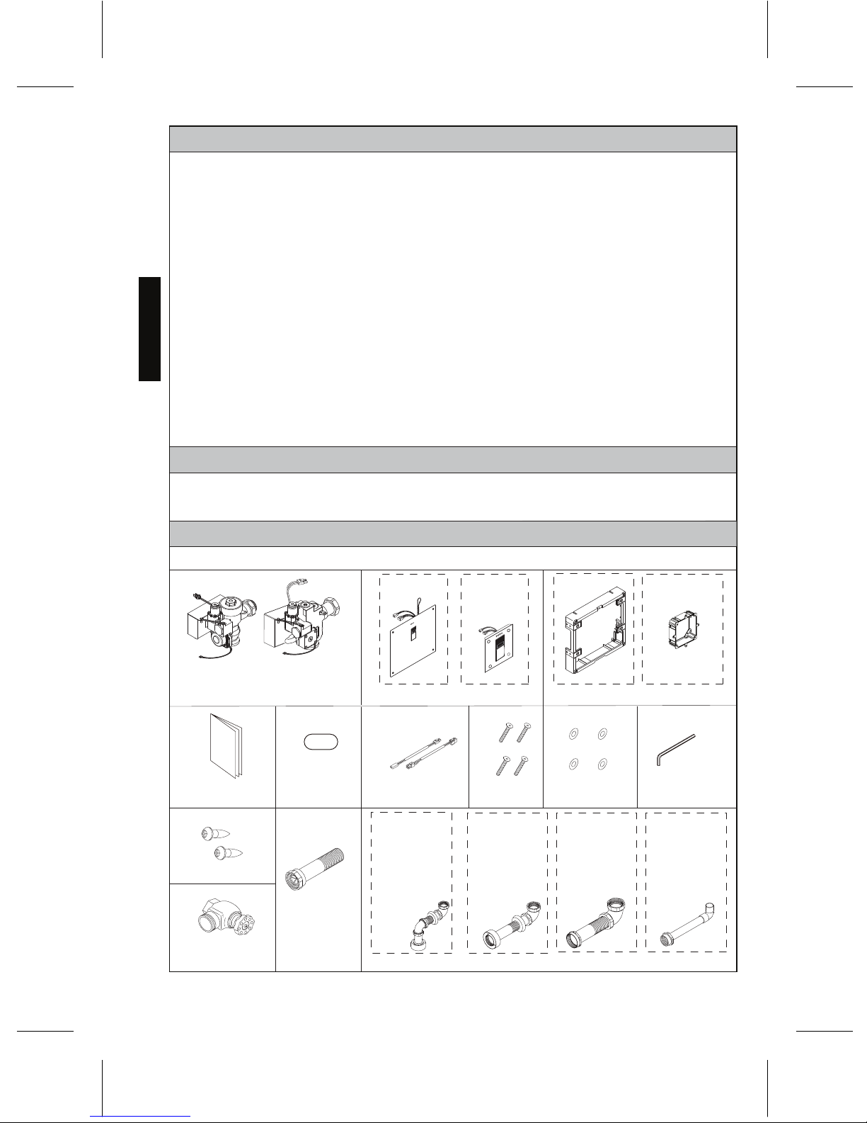
TABLE OF CONTENTS
THANKS FOR CHOOSING TOTO!
Thanks for Choosing TOTO!...................................................................................................................2
Included Parts.............................................................................................................................................2
Common Tools Needed............................................................................................................................3
Initializing the Ecopower Product .............................................................................................................3
Features..................................................................................................................................3
Specifications..........................................................................................................................4
Technical Information.................................................................................................................................5
Warnings..........................................................................................
................................................6
Before Installation.......................................................................................................................................6
Installation Procedure.................................................................................................................................7
Test Run.....................................................................................................................................................14
Note to the Installer..................................................................................................................................15
Using the Flush Valve.............................................................................................................................15
Troubleshooting.................................................................................................................................16
Warranty.........................................................................................................................................20
Rough-In Dimensions...............................................................................................................................78
Reclaimed Water Specifications....... .......................................................................................................81
The mission of TOTO is to provide the world with healthy, hygienic and more comfortable
lifestyles. We design every product with the balance of form and function as a guiding principle.
Congratulations on your choice.
ENGLISH
2
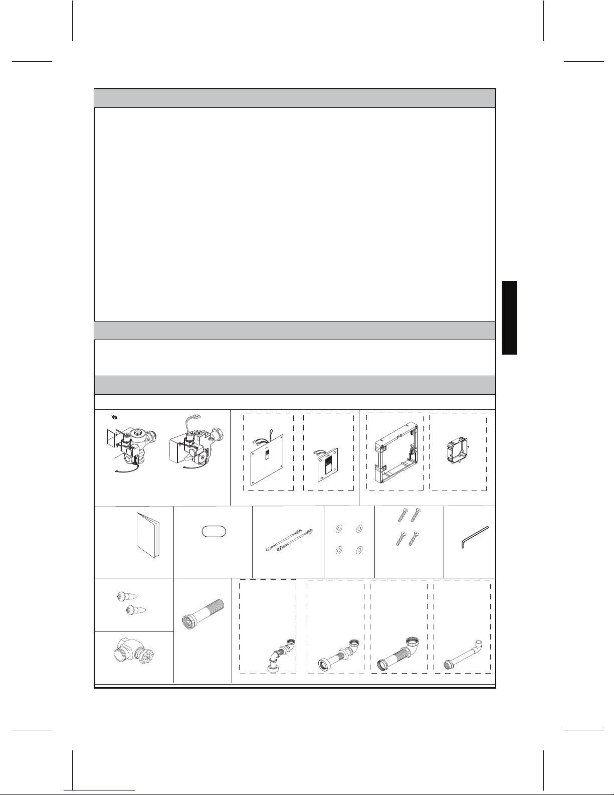
INCLUDED PARTS
Check to make sure you have all these parts from the package:
Valve body assembly
Front cover
Base frame
Hex wrench
Notice label
Installation And
Owner's Manual
(TEU2UA(R)(X) only)
Vandal proof
hex screws
Washer
Large cover Small cover Large cover Small cover
(TEU3UA(R)(X) only)
Vacuum
breaker tube
Control stop
Flush pipe
Screws
Connection cables
Small cover only
Periodic Maintenance...............................................................................................................................15
TEU3LA(X)11
TEU3UA(X)11
TEU2LA(X)21
TEU2UA(X)11
TEU3LA(X)21
TEU2LA(X)11
TET3GA32
TET3LA(X)32
TET3UA(X)32
TET2GA32
TET2LA(X)32
TET2UA(X)32
TEU3LA(X)12
TEU3UA(X)12
TEU2LA(X)12
TEU2UA(X)12
TET3GA33
TET3LA(X)33
TET3UA(X)33
TET2GA33
TET2LA(X)33
TET2UA(X)33
TET3GA31
TET3LA(X)31
TET3UA(X)31
TET2GA31
TET2LA(X)31
TET2UA(X)31
Care & Cleaning .......................................................................................................................................15
Page 3
FEATURES
Fully Automatic and Hygienic
The EcoPower Flush Valve uses an infrared sensor to detect the user using and departing the
fixture, to provide an automatic flush of the fixture after a short delay. No manual operation is
required, improving the experience of use and hygiene of the fixture.
System Protection Timer
When the fixture is not used for 24 hours for toilet or 12 hours for urinal the protection
timer commands the system to flush in order to maintain the trap seal.
Manual Functionality
For maintenance and emergency use, the EcoPower Flush Valve is equipped with a manual
flushing button.
Green Features
Conserves Power
The flushing of the fixture activates a hydropower generator which generates electric power for
the next flush. (See About TOTO’s Hydropower Generator, page 5)
Conserves Water
Two functions help the EcoPower Flush Valve conserve water:
Fuzzy Logic Control
The EcoPower Flush Valve can sense how often and how long the fixture has been used to
deliver the correct amount of water. (See About Fuzzy Logic Control, page 5)
Anti Consecutive Flushing
The EcoPower Flush Valve offers water saving consecutive flush prevention. After a flush, the
valve will not automatically flush again for 10 seconds for urinals and 30 seconds for toilets.
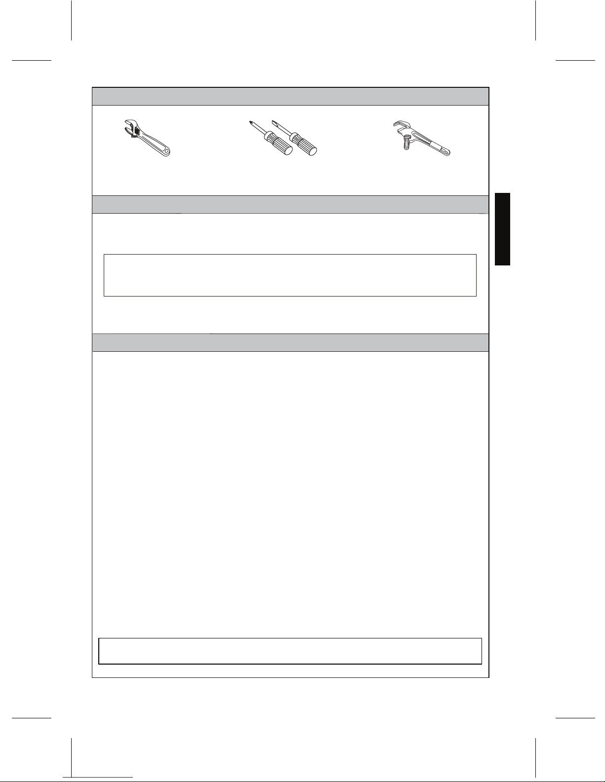
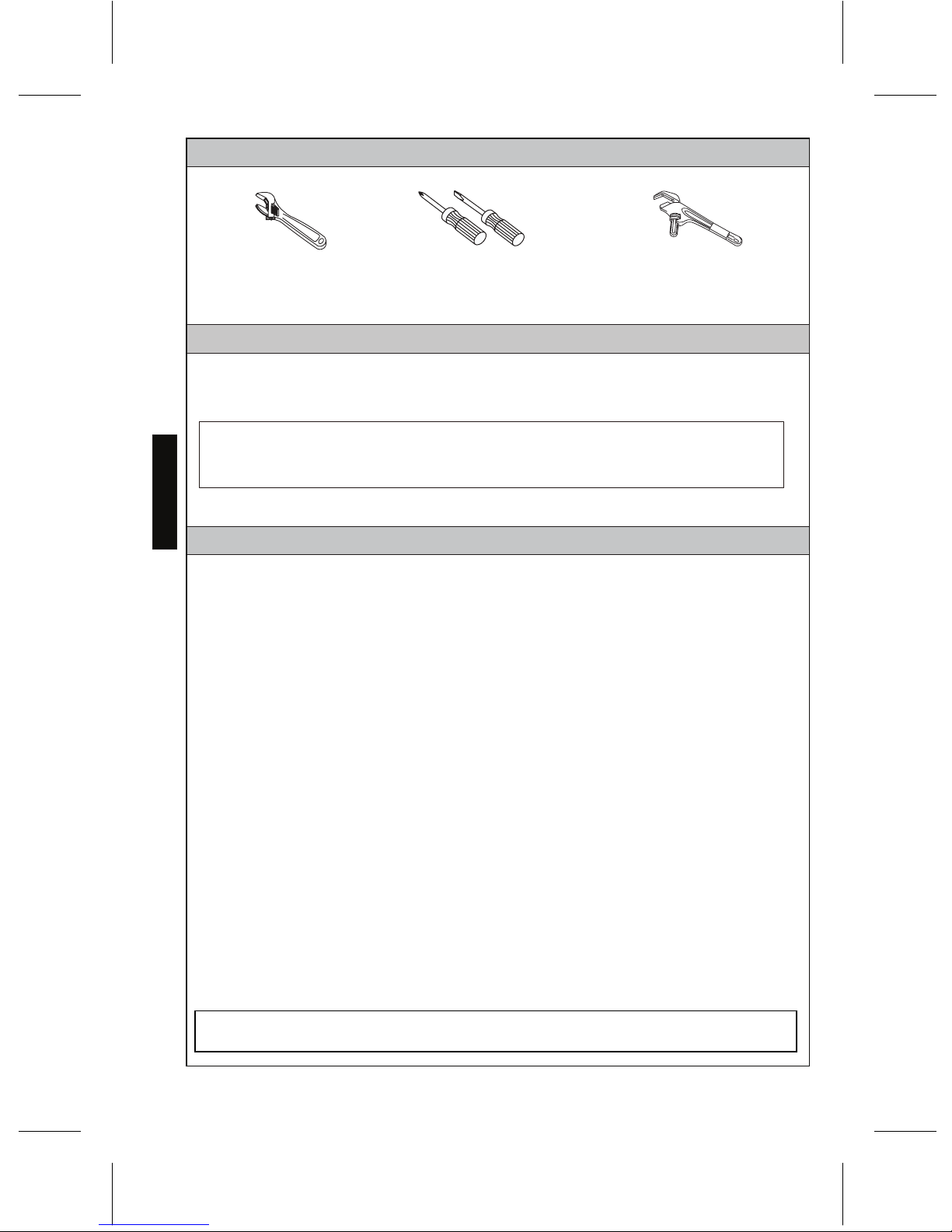
COMMON TOOLS NEEDED
TOTO EcoPower Flush Valves are designed to work for 10 years, under normal conditions,
with no minimum usage required.
Screwdrivers (Phillips and Slotted )
Adjustable wrench
INITIALIZING THE ECOPOWER PRODUCT
ENGLISH
3
Offset pipe wrench
It will take approximately 5 minutes after connecting the battery for the electronics to initialize.
This delay is a normal part of startup.
After approximately 30 seconds, the sensor LED will start flashing in 4 second intervals until
the initialization is complete.
Thank you for choosing the latest innovation in low power consumption EcoPower products.
Please note below the duration of time required to initialize the electronics.
Page 4
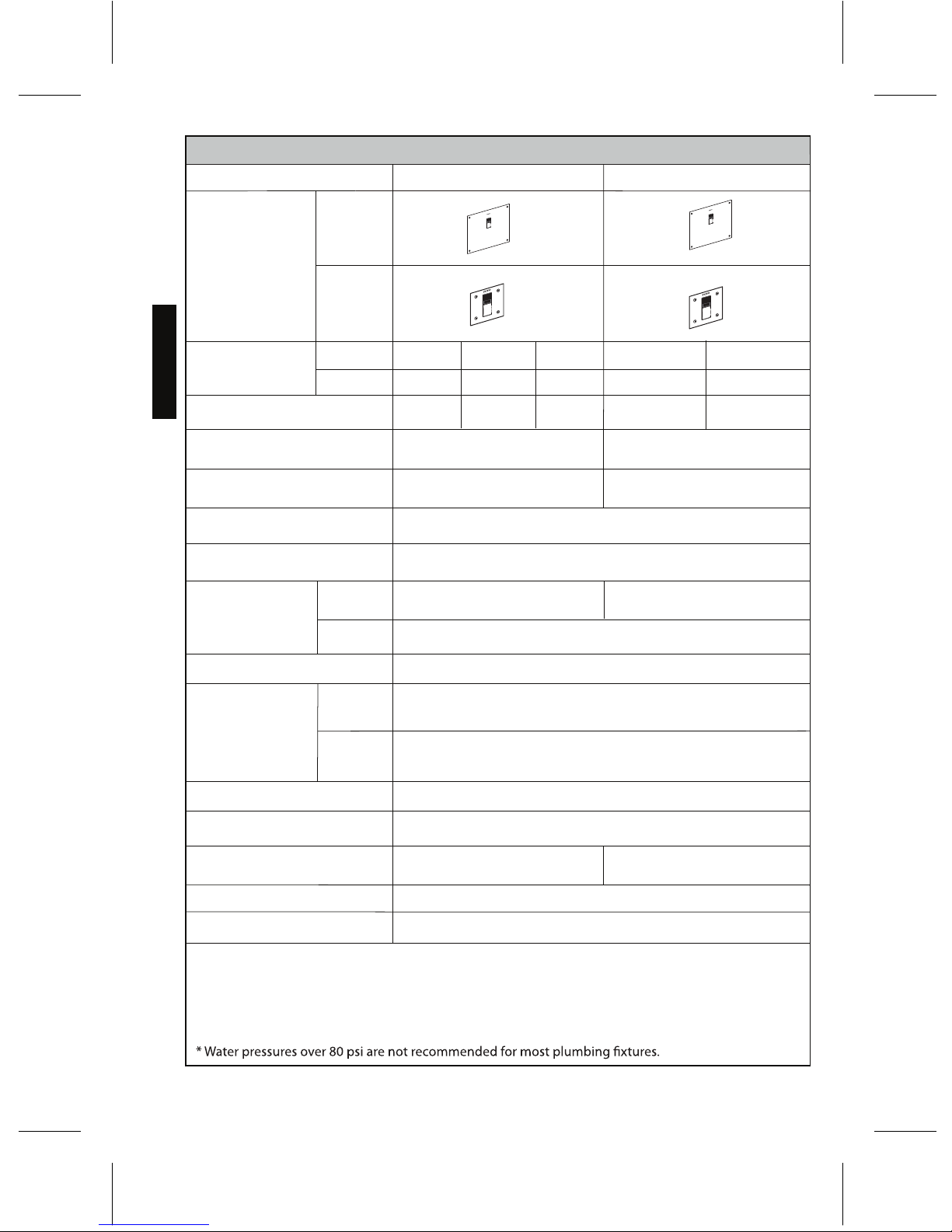
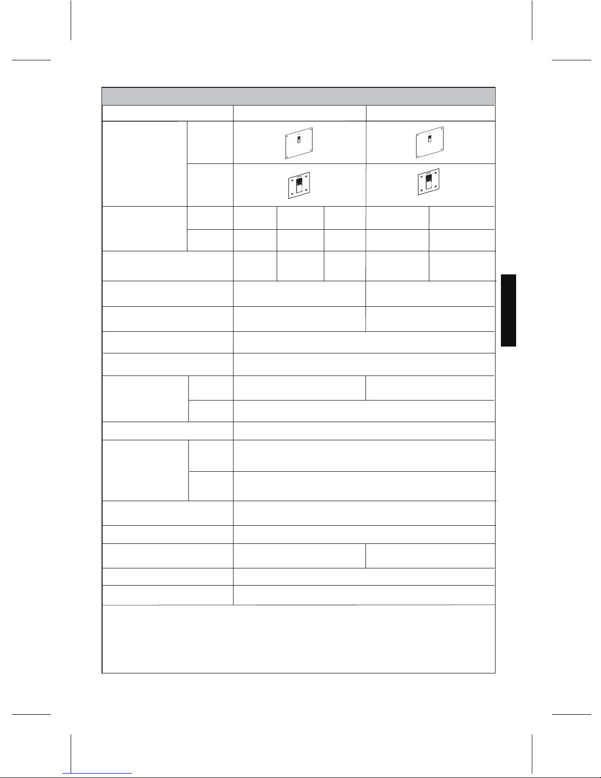
SPECIFICATIONS
32-104˚F (0-40˚C)
34-104˚F (1-40˚C)
1"NPT 3/4"NPT
1-1/4"NPSM
1-1/2"NPSM
7 psi (48kPa)
Flush Valve type Wash down flush
Automatic flushing every
24 hours of non-use
Model number
Detection time
Figure
Ambient temperature
Water temperature
Control stop inlet
Flush Valve inlet
Flush Valve outlet
Supply water
pressure
Shutoff pressure
Rated Flush Volume
Toilet/Urinal type
Trap seal protection
TET2GAR
TET3GAR
Toilet Urinal
Min
Max*
35 psi (241kPa)
(Flowing)
15psi (103kPa)
125 psi (862kPa)
1.6 G (6L)
0.5 G (1.9L)
Automatic flushing every
12 hours of non-use
0.125 G (0.47L)
6 seconds
NOTE:
Small cover
Large cover
TEU2LA(R)(X)
TEU3LA(R)(X)
TEU2UA(R)(X)
TEU3UA(R)(X)
Large cover
Small cover
12-5/8" (H) ×14-3/16"(W)
(320mm(H) ×360mm(W))
Dimension
of cover
Large cover
Small cover
4-23/32" (H) ×4-23/32"(W)
(120mm(H) ×120mm(W))
tnorf eht morf egnar noitceteD
Within 33-1/2" (850mm)
(Static)
The type of fixture determines the minimum pressure required for the valve. Consult
fixture manufacturer for the overall pressure requirement.
ENGLISH
4
TET2UA(R)(X)
TET3UA(R)(X)
1.0 G (3.8L)
TET2LA(R)(X)
TET3LA(R)(X)
1.28 G (4.8L)
Page 5

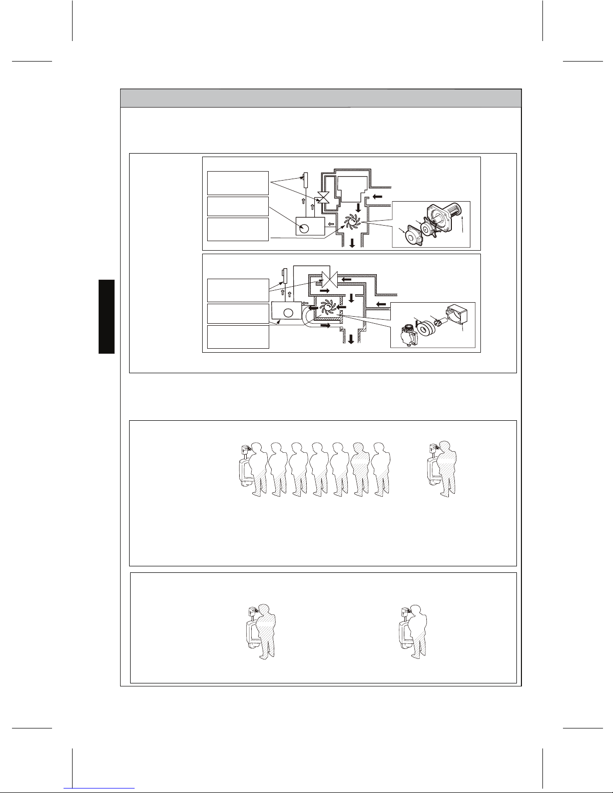
About Fuzzy Logic Control (TEU1GAR only)
About TOTO's Hydropowered Generator
1) A turbine rotates to
generate electric
power.
3) The Automatic
Flush Valve uses the
charged power.
2) Electric power is
stored in a capacitor.
Sensor Eye
Controller
Piston
Water Supply
Flush Valve
Coil
Turbine
Cover
1)
A turbine rotates to
generate electric
power.
3)
The Automatic
Flush Valve uses the
charged power.
2)
Electric power is
stored in a capacitor.
Sensor Eye
Controller
Flush Valve
Water Supply
Cover
Turbine
Coil
TET2LA(R)(X)
TET2GAR
TET3LA(R)(X)
TET3GAR
TEU2LA(R)(X)
TEU3LA(R)(X)
TEU2UA(R)(X)
TEU3UA(R)(X)
TECHNICAL INFORMATION
The flow of water causes the turbine in the power generator to rotate. This process generates
electric power and enables the automatic Flush Valve to operate. See ill. 1 below.
The Fuzzy Logic Control function automatically adjusts the discharge of water according to the
frequency and duration of usage (see ill. 2 and ill. 3).
ill. 1 Hydropowered Generator
ENGLISH
5
High Frequency of Usage Low Frequency of Usage
Less Less Less Less Less LessTypical
Long duration of usage Short Duration of Usage
Less
Typical
If the idle time is short, the system assumes frequent use
and the Flush Valve discharges less water.
Examples of high frequency use would be during a lunch
break or an intermission in a movie theatre.
A short duration of use
indicates there may be
less to flush, requiring the
Flush Valve to discharge
less flush water.
If the idle time is long, the system
assumes infrequent use, causing the
Flush Valve deliver a typical quantity of
water for thorough flushing.
Examples of low frequency use would be
during after hours at the office or a slow
day at the park.
The Fuzzy Logic
Control system judges
the frequency of
usage by the idle time
of the fixture and
causes the Flush Valve
to discharge water in
an optimal flushing
pattern.
The Fuzzy Logic Control
system predicts the
quantity of flush water
needed based on the
user's duration of use.
A long duration of use indicates
there may be more to flush,
requiring the Flush Valve to
deliver a typical quantity of flush
water for thorough flushing.
ill. 2 Frequency of Usage
ill. 3 Duration of Usage
TET2UA(R)(X)
TET3UA(R)(X)
Typical
Page 6
BEFORE INSTALLATION
WARNINGS
IMPORTANT: Plumbing installation must be in accordance with applicable codes and
regulations. Water supply lines must be sized to provide an adequate volume of water for
each fixture. Flush all waterlines prior to operation.
Prior to installing your Flush Valve, install the items listed below:
Bowl fixture/Urinal fixture
Drain line
Water supply line
The supply piping to these devices must be securely anchored to the building structure to
prevent the installed device moving during use. Prevent marring to the exposed surface
during installation.
IMPORTANT:
Purge all air from the supply lines before connecting
flush valve to the bowl. Trapped air in supply lines may crack the china.
Avoid damaging the surface of the infrared sensor while unpacking.
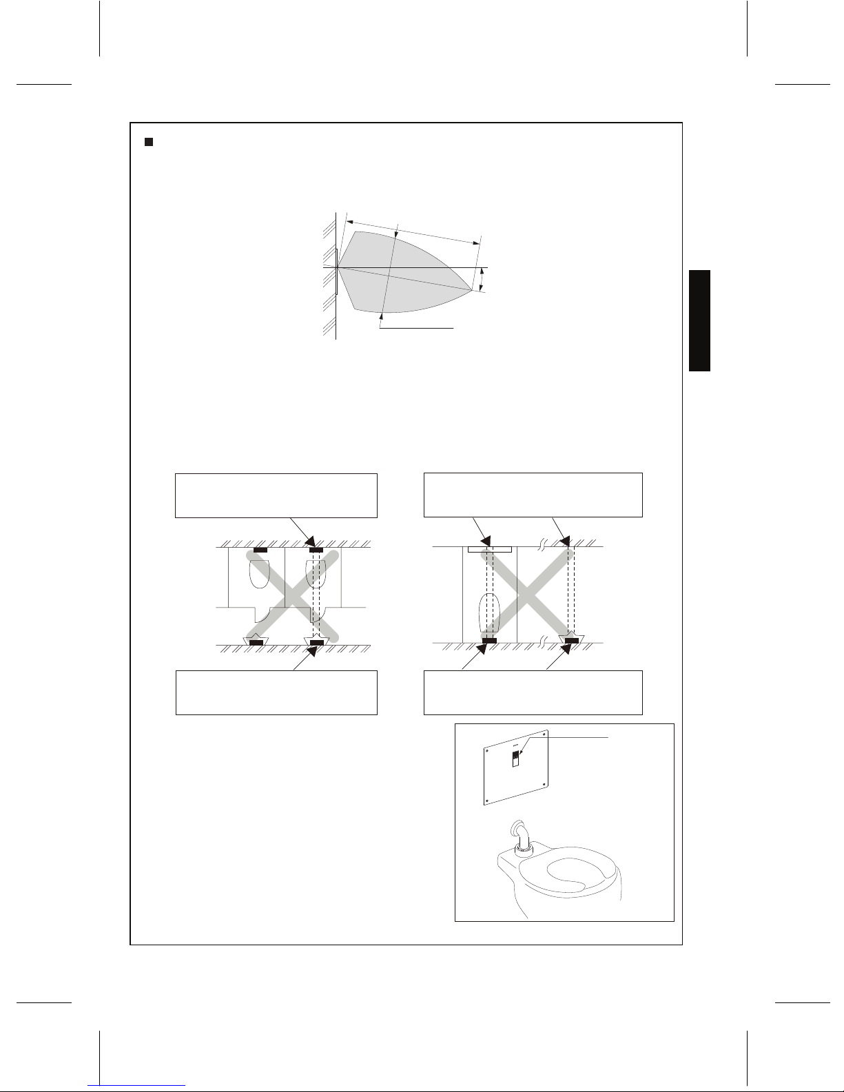
For Toilet Flush Valve:
The toilet Flush Valve may not function if toilet seat or lid cover are left upright and block the
sensor.
For Urinal Flush Valve:
The urinal Flush Valve is designed for optimal performance with a washout urinal, but a
siphon jet urinal may be substituted. Blowout urinals are not recommended.
The detection range of the infrared sensor is shown on p.19.
To prevent valve malfunction, do not install a handrail or any other object within the detection
range of the sensor. Do not install the Flush Valve where sensor faces a mirror, stainless steel
wall, other highly reflective surfaces or another infrared sensor.
Please read and adhere to these notes. Failure to do so could result in personal injury and/or
property damage.
Never splash water on the controller. The EcoPower Flush Valve is an electric appliance.
Risk of product malfunction.
Do not strike or kick the EcoPower Flush Valve. Risk of product malfunction or water
leakage.
Do not use the EcoPower Flush Valve at temperatures exceeding what local codes or
product specification allow. Risk of product malfunction.
Do not place an item in a room with high humidity such as shower area or sauna. Risk of
product malfunction.
Never attempt to disassemble, reassemble, repair or modify the EcoPower Flush Valve
unless you are a professional. Risk of product malfunction and electric shock.
Do not use standard vacuum breaker or control stop with reclaimed water flush valve.
Do not use petroleum based products or pipe sealants, doing so could damage product
and cause water damage.
ENGLISH
6
For Reclaimed Water Flush Valve:
Only use reclaimed water angle stop and vacuum breaker.
Toilet and urinal Flush Valves are not interchangeable, check the model number on the label to
make sure you have the correct type. Toilet Flush Valve model numbers begin with ‘TET’ and
Urinal Flush Valve model numbers begin with ‘TEU’.
Page 7
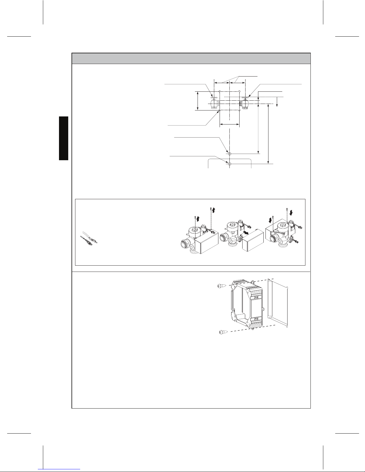
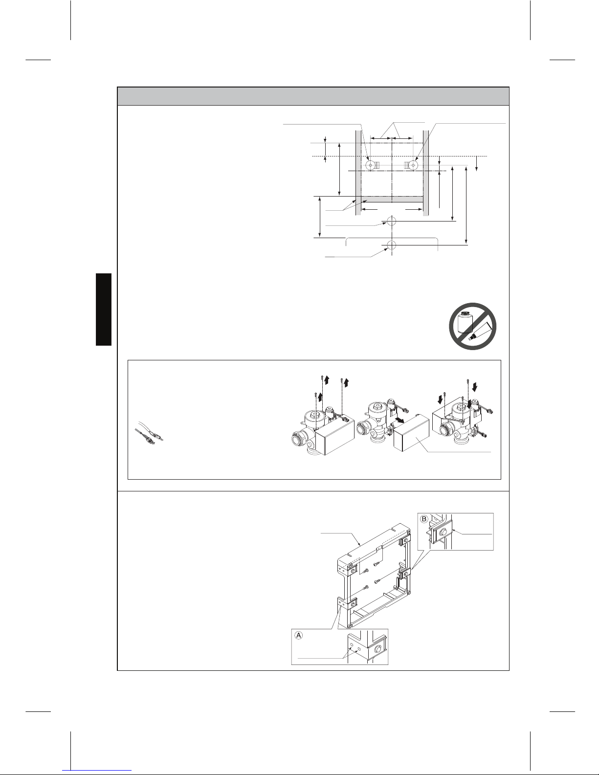
INSTALLATION PROCEDURE — LARGE COVER
NOTE:
Base frame
Adjustable
plate
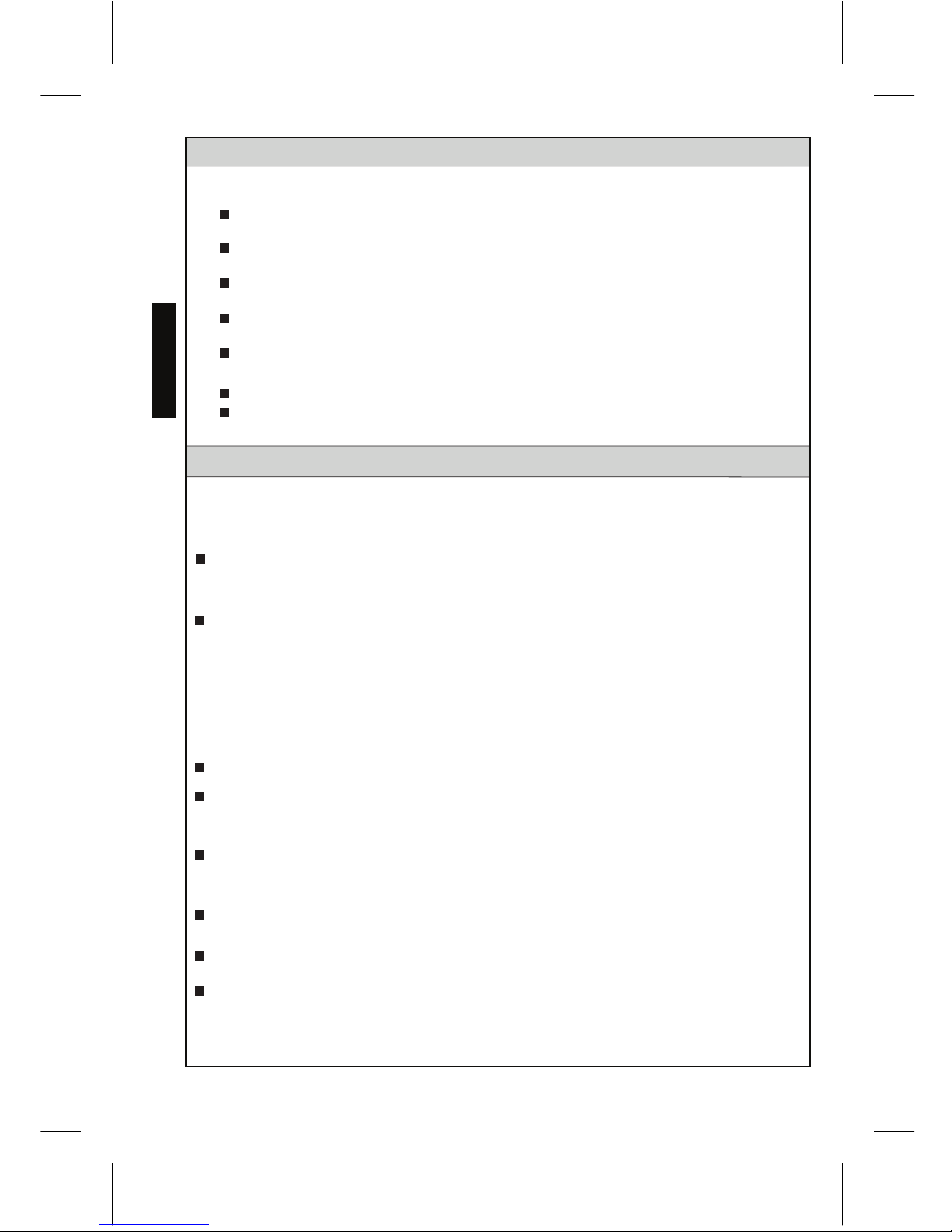
1. Determine the installation location of
the studs and water supply pipe
relative to the position of the
toilet/urinal.
3. Attach the control stop to the pipe.
4. Bore a guide hole for the flush pipe
into the wall.
Attach the control stop
NOTE:
For reclaimed water, do not use
standard vacuum breaker or
control stop.
NOTE:
Do not use petroleum based products
or pipe sealants.
before installing the box
fixing frame. Thread sealing
compounds should only be
used on the male NPT
threads only.
5. Fasten the base frame to the studs with
four screws (prepared on site) after
adjusting it. ( A )
6. Secure the box with four screws in the
adjustable plate. ( B )
For use with a left water supply,
detach the controller and remount it
to opposite side of valve body.
Detatch Remount
Valve body
7
ENGLISH
Adjustable holeAdjustable hole
Left water supply
1” NPT (toilet), 3/4” (urinal)
4-3/4” ± 1/2”
(120 ± 13mm)
Sensor location
3-7/16” (87mm)
** 11-15/16”
(303mm)
16” (406mm)
3/4” (19mm)
Stud
Toilet top spud
Ø2-3/16” (Ø56mm) hole
Urinal back spud
Ø1-5/16” (ø33mm) hole
Toilet back spud
Ø2-3/16” (ø56mm) hole
11” (279mm)
CL of sensor
* X”
** 13-1/2”
(343mm)
* 14-3/4” ‡
from top of
Urinal top spud
Ø1-1/2” (Ø38mm) hole
* X”, ‡ = At least 5” clearance from sensor to tip of toilet seat up position or
to top of grab bar is required to avoid false detection.
** Opening in wall
Right water supply
1” NPT (toilet),3/4” (urinal)
2. If needed, slide a thread solder
adapter on the water supply pipe.
inside the controller’s case.
Protect the wire connections
D
O
N
O
T
U
S
E
P
E
T
R
O
L
E
U
M
-
B
A
S
E
D
S
E
A
L
A
N
T
S
A
T
T
E
N
T
I
O
N
!
Page 8
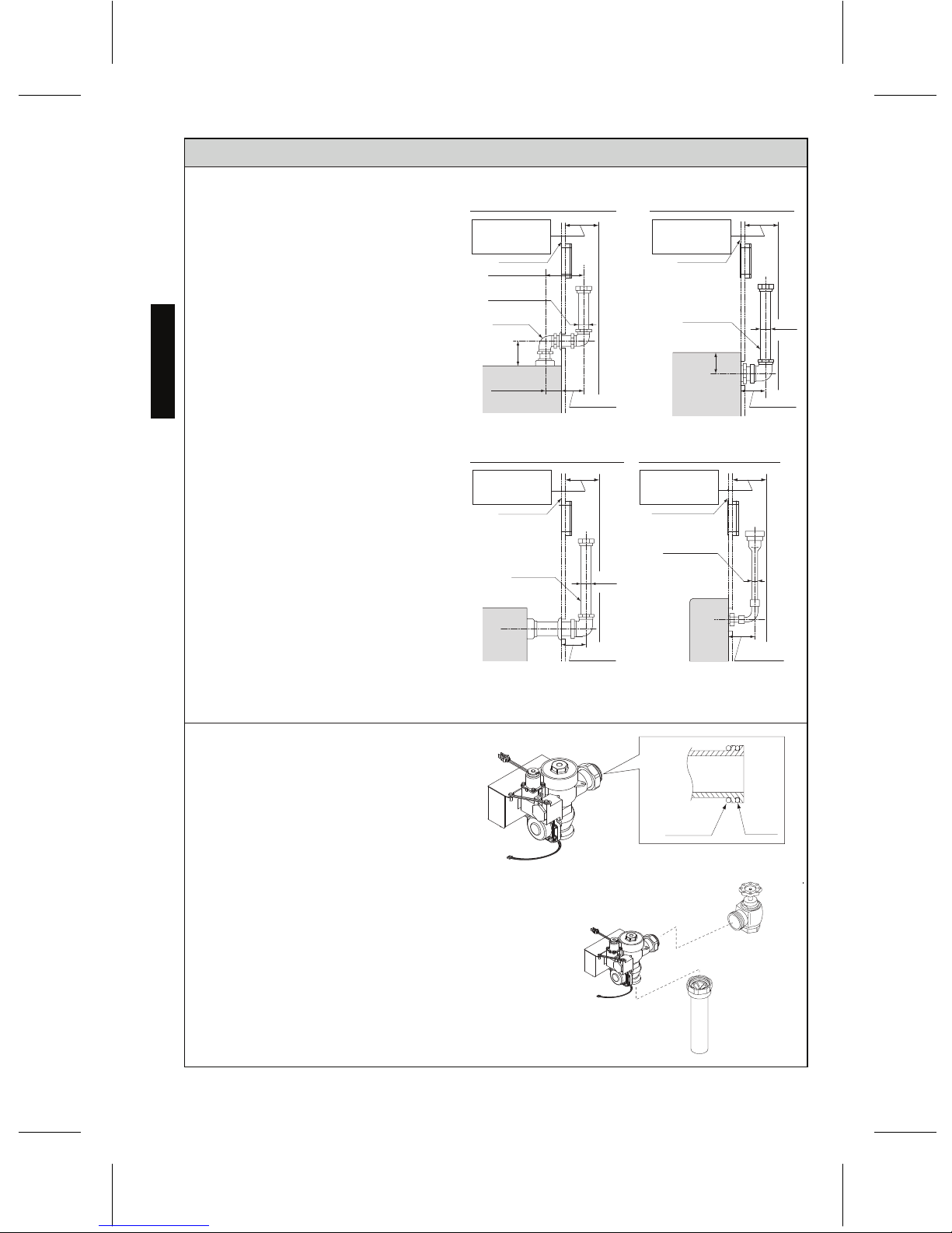
INSTALLATION PROCEDURE
— LARGE COVER
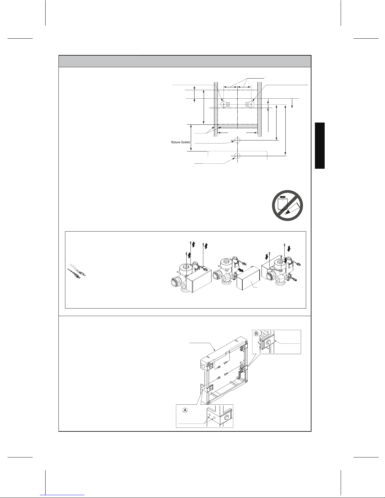
7. Pass the flush pipe and the vacuum
breaker through the guide hole (Step
3) and mount them on the bowl.
8. If required, cut the vacuum breaker
tube to the proper length.
9. Make sure that the o-ring fits in the
groove at the end of the Flush Valve
tailpiece.
NOTE: Exercise care to avoid damaging the
o-ring when inserting the tailpiece
into the control stop. If lubrication is
needed, wet the o-ring with water.
10. Connect the Flush Valve with the control
stop and vacuum breaker tube.
8
ENGLISH
TET2LA(X)32, TET2GA32, TET2UA(X)32
TEU2LA(X)12, TEU2UA(X)12
TET2LA(X)31, TET2UA(X)31
TET2GA31
TET2LA(X)33, TET2UA(X)33,
TET2GA33
TEU2LA(X)11, TEU2LA(X)21
TEU2UA(X)11
Bowl or Urinal
Wall surface
6~6-1/2”
(152~165mm)
1-1/2” (38mm)
or 3/4” (19mm)
1-1/2”
(38mm)
5”
(127mm)
2-1/4”~2-3/4”
(57~70mm)
3-3/4”~4-7/8”
(95~124mm)
3-3/4”~4-7/8”
(95~124mm)
Top spud
Back spud
Wall mount
3”
(76mm)
Bowl
3-3/4”~4-7/8”
(95~124mm)
3-3/4”~4-7/8”
(95~124mm)
Urinal
Back spud
Floor mount
Bowl
1-1/2”
(38mm)
1-1/4” (32mm)
or 3/4” (19mm)
7” (178mm) Min space
requirement in wall
Wall surface
Wall surface
Wall surface
7” (178mm) Min space
requirement in wall
7” (178mm) Min space
requirement in wall
7” (178mm) Min space
requirement in wall
Page 9
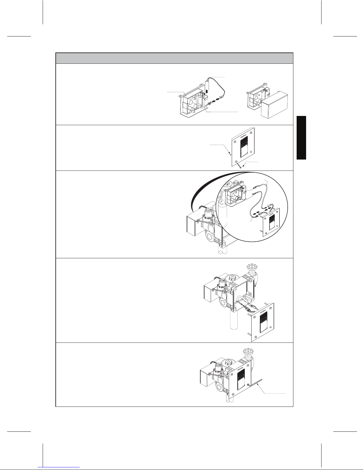
INSTALLATION PROCEDURE — LARGE COVER
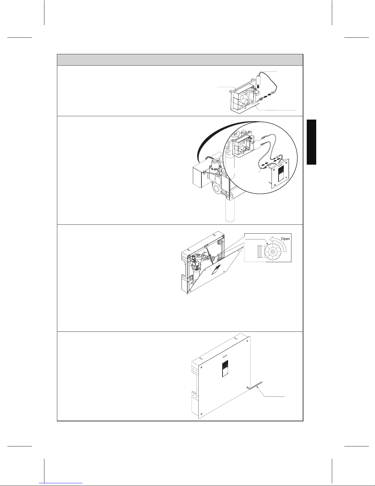
Hex wrench
Control stop
NOTE:
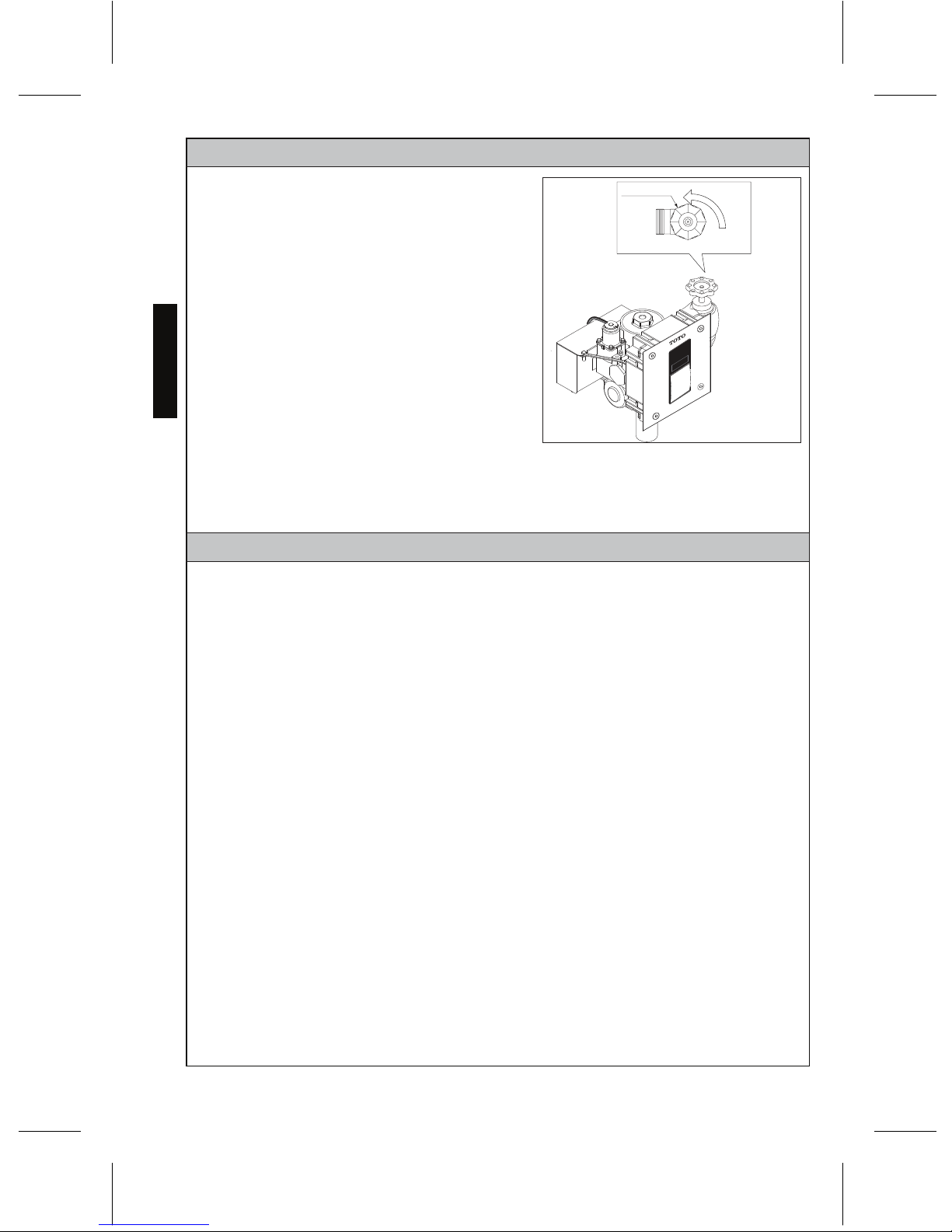
15. To set the Flush Valve for proper
operation, open the control stop
completely and activate the Flush
Valve several times.
16. In the case of excessive flow rate
because of high water pressure,
gradually adjust the control stop
clockwise (towards the closed position)
until there is suitable water flow into
the fixture.
17. Tighten the front cover screws into
the base frame firmly with the hex
wrench.
Make sure no cord, wire or chain is
caught between the front cover and
base frame.
9
ENGLISH
The control stop should never be opened
to the point where the flow from the Flush
Valve exceeds the flow capability of the
fixture. In case of a valve failure, the water
must overflow from fixture.
The Flush Valves are preset for flush volume as
marked on the valve carton. The valve does not
require adjustment for variation in water pressure
within its operating range.
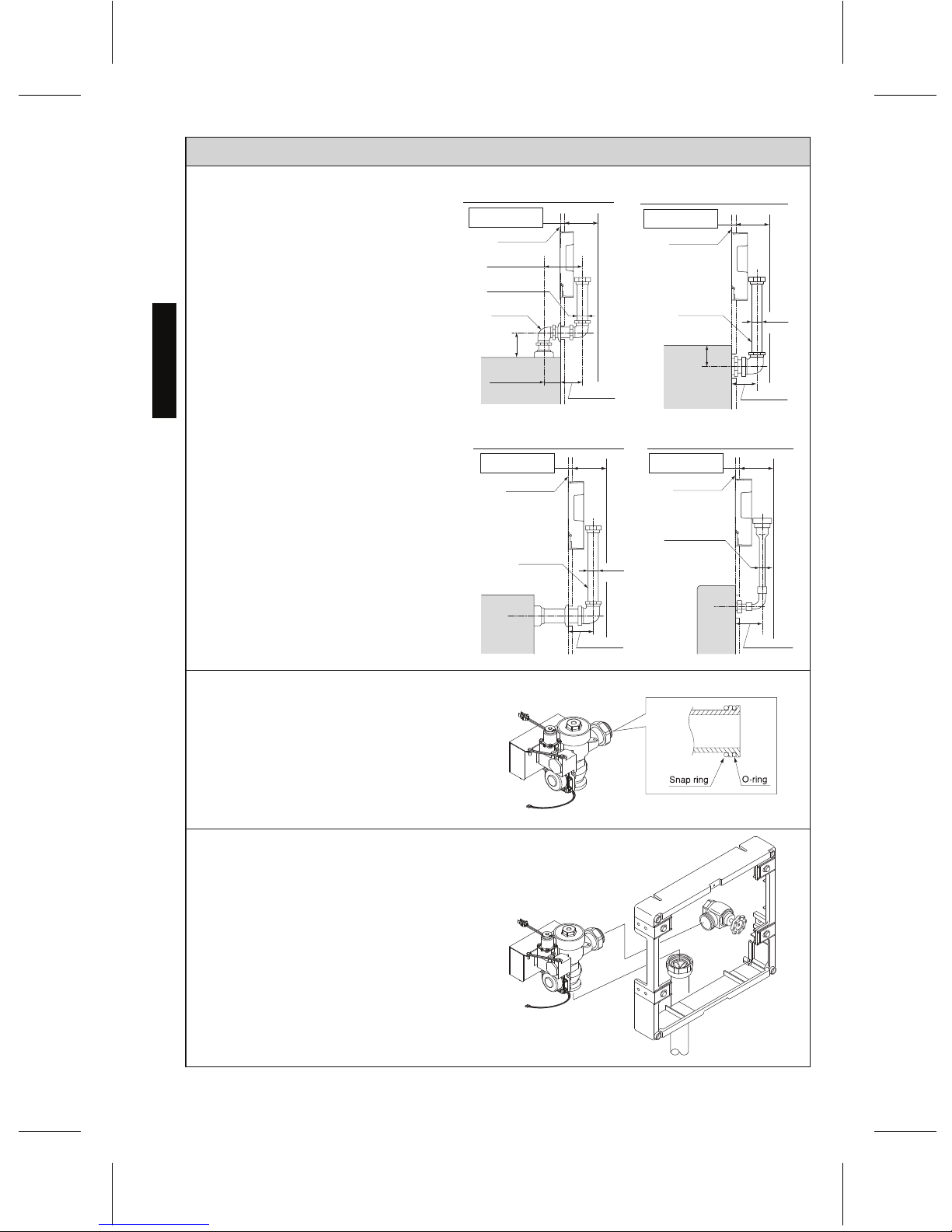
11. Connect the cables of the battery
and controller and set the battery
in place.
Connection cable
(button)
Connection cable
(sensor)
Battery
Controller
Connection cable
14. Ensure all pipe connections are completely
tightened to prevent leaking.
NOTE:
12. Connect the cables of infrared sensor
and controller with the connection
cable.
13. Connect the cables of manual button
and controller with the connection
cable.
NOTE:
It will take 5 minutes after connecting the
battery for the electronics to initialize.
After approximately 30 seconds, the
sensor LED will flash in 4 second intervals
until the initialization completes.
If for any reason it becomes necessary to
remove the control stop make sure the water
is shut off at the main supply valve.
Page 10
10
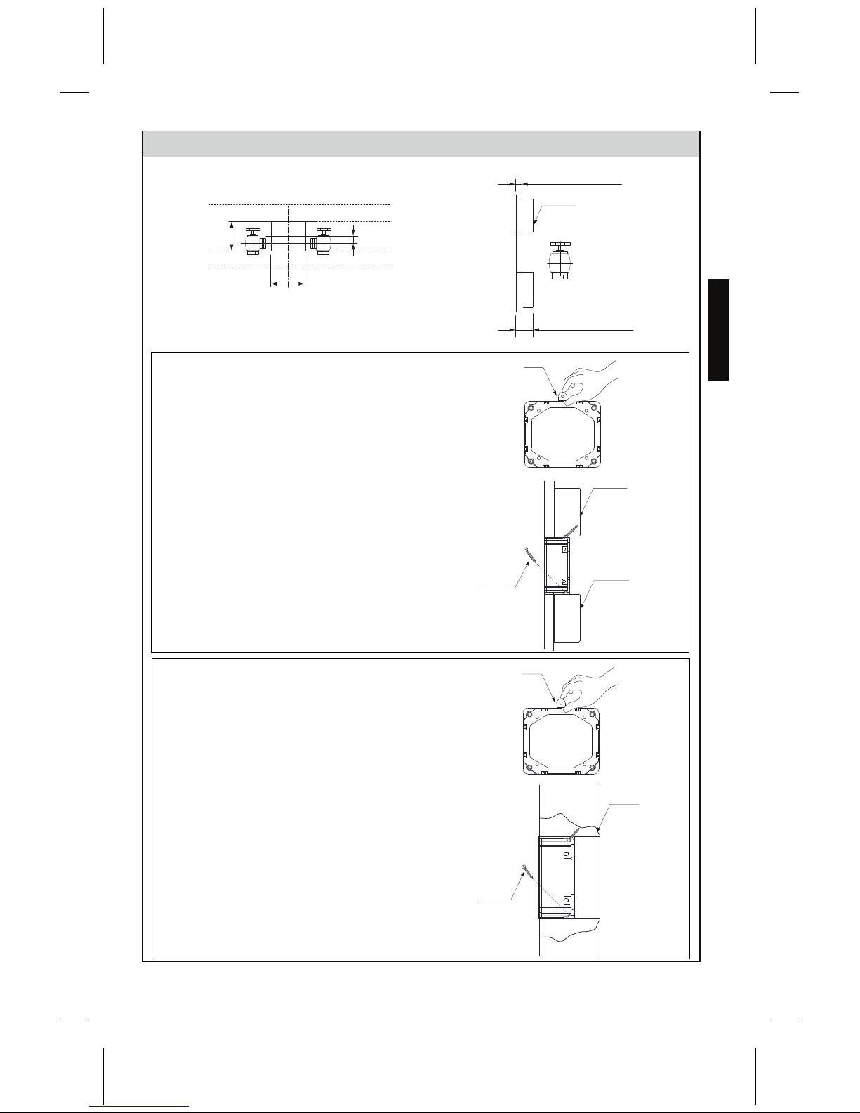
INSTALLATION PROCEDURE — SMALL COVER
NOTE:
To use with a left water supply, detach
the controller and remount it to
opposite side of valve body.
5. Secure back frame to the wall with two screws the
base frame. Other base frame installation options
with stringer and for concrete wall on next page.
Wall thickness must be 1/2" (13mm)
minimum and 1-3/8"(35mm) maximum.
If your wall thickness is less than
1/2" (13mm), please attach wooden
frame behind the wall.
1. Determine the location of the
water supply pipe.
3. Attach the control stop to
the pipe.
4. Bore a guide hole for the flush
pipe into the wall.
NOTE: Thread sealing
compounds should be
used on the male NPT
threads only.
Detatch
Remount
ENGLISH
4 x Ø5/16" (Ø8mm) hole
Left water supply pipe
1”NPT (toilet), 3/4” (urinal)
Right water supply pipe
1”NPT (toilet), 3/4” (urinal)
Toilet top spud
Ø2-3/16” (Ø56 mm) hole
Urinal back spud
Ø1-5/16” (Ø33 mm) hole
Toilet back spud
Ø2-3/16” (Ø55 mm) hole
X”
1-1/4” (31 mm)
CL of sensor
** 3-11/16”
(94mm)
11” (279mm)
16” (406mm)
** 3-11/16”
(94 mm)
* X”, ‡ = At least 5” clearance from sensor to tip of toilet seat up position or
to top of grab bar is required to avoid false detection.
** Opening in wall
4-3/4” ± 1/2”
(120 ± 13mm)
Urinal top spud
Ø1-5/16” (Ø33 mm) hole
2. If necessary, slide a sweat
solder adapter on the water
supply pipe
Protect the wire connections
inside the controller’s case.
Page 11
11
INSTALLATION PROCEDURE— SMALL COVER
Option 5A (with stringer)
Max.1”(25mm)
Min.1-3/8”(35mm)
Screws
Stringer
Stringer
Tab
Stringer
Option 5B (for concrete wall)
Screws
Mortar
Tab
1. Remove all tabs on side of the base frame.
2. Fasten the base frame to stringer with 4 screws
(prepared on site).
1. Cut out a place for the cover into the wall.
2. Remove all tabs on side of the base frame
before installation.
3. Fix the base frame into place with mortar.
4. Secure the base frame with 4 screws
(prepared on site), if needed.
Other base frame installation options
ENGLISH
4-1/3”
(110mm)
4-1/3”
(110mm)
3/4”
(19mm)
Page 12
12
INSTALLATION PROCEDURE — SMALL COVER
Snap ring
O-ring
8. Make sure that the o-ring fits in the
groove at the end of the Flush Valve
tailpiece.
9. Exercise care to prevent damage to
the o-ring when inserting the tailpiece
into the control stop. For additional
lubrication, wet the o-ring with water.
6. Pass the flush pipe and the vacuum
breaker through the guide hole (Step 3)
and mount them on the bowl.
7. If required, cut the vacuum breaker
tube to the proper length.
10. Connect the Flush Valve with the control
stop and vacuum breaker tube.
11. Tighten the coupling nut with a wrench to
prevent a water leak.
ENGLISH
TET3LA(X)32, TET3GA32, TET3UA(X)32
TEU3LA(X)12, TEU3UA(X)12
TET3LA(X)31, TET3UA(X)31
TET3GA31
Bowl or Urinal
6~6-1/2”
(152~165mm)
1-1/2” (38mm)
or 3/4” (19mm)
1-1/2”
(38mm)
5”
(127mm)
2-1/4”~2-3/4”
(57~70mm)
3-3/4”~4-7/8”
(95~124mm)
3-3/4”~4-7/8”
(95~124mm)
Top spud
Back spud
Wall mount
3”
(76mm)
Bowl
TET3LA(X)33, TET3UA(X)33
TET3GA33
TEU3LA(X)11, TEU3LA(X)21
TEU3UA(X)11
3-3/4”~4-7/8”
(95~124mm)
Urinal
Back spud
Floor mount
Bowl
1-1/2”
(38mm)
1-1/4” (32mm)
or 3/4” (19mm)
Wall surface
Wall surface
Wall surface
Wall surface
7" (178mm) min space
in wall with a min
12" x 12" access panel
or walk-in chase
7" (178mm) min space
in wall with a min
12" x 12" access panel
or walk-in chase
7" (178mm) min space
in wall with a min
12" x 12" access panel
or walk-in chase
7" (178mm) min space
in wall with a min
12" x 12" access panel
or walk-in chase
3-3/4”~4-7/8”
(95~124mm)
Page 13
13
INSTALLATION PROCEDURE — SMALL COVER
Hex wrench
Washer
Screw
12. Connect the battery cable with the
controller and set the battery in place.
13. Attach the vandal proof screws the
front cover using washers.
16. Before the supply water is turned on, be
sure all water leaks are eliminated by
tightening all the pipe connections.
If for any reason it becomes necessary to
remove the control stop, make sure the
water is shut off at the main supply valve.
17. Fasten the front cover to the base frame
by tightening the screws with the
supplied hex wrench.
18. Take care so that any cord, wire or chain
might not be caught between the front
cover and the box.
14. Connect the cables of infrared sensor
and controller with the connection
cable.
15. Connect the cables of manual button
and controller with the connection
cable.
ENGLISH
Connection cable
(button)
Connection cable
(sensor)
Battery
Controller
Connection cable
NOTE:
It will take 5 minutes after connecting the
battery for the electronics to initialize.
After approximately 30 seconds, the
sensor LED will flash in 4 second intervals
until the initialization completes.
NOTE:
Page 14
14
INSTALLATION PROCEDURE — SMALL COVER
WARNING: Do not open the control stop to the point where the flow from the Flush Valve
exceeds the flow capability of the fixture. In case of a valve failure, the water
must not overflow from the fixture.
Control stop
Open
The Flush Valves are preset for flush volume as
marked on the valve carton. The valves do not
require adjustment for variation for water pressure
within its operating range.
19. Open the control stop completely.
20. Activate the Flush Valve several times.
21. In the case of excessive flow rate, adjust the flush
volume, gradually adjust the control stop clockwise, towards the closed position, until there is
suitable water flow into the filter.
ENGLISH
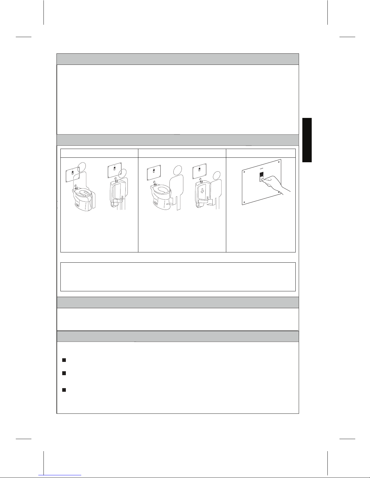
TEST RUN
1. For Toilet: Sit on the toilet seat.
For Urinal: Stand within two feet from the front of the Flush Valve.
2. Stay there for 6 seconds or more and then leave the toilet seat or the urinal. The valve
should automatically flush, immediately for urinals and after 3 seconds for toilets.
3. Press the manual flushing button. The toilet or urinal should flush and the red
light of the sensor should flash. To correct overflow from a urinal Flush Valve, adjust the
control stop clockwise.
4. Recheck all the pipe connections for water leaks. If the Flush Valve is not operating
properly following the test run consult the Troubleshooting section on p.16.
After connecting the battery, the initialization process takes 5 minutes. After approximately 30
seconds, the sensor LED will start flashing in 4 second intervals until the initialization is
complete. Please wait before starting the Test Run.
Page 15
15
ENGLISH
PERIODIC MAINTENANCE
Please check the piping to your EcoPower Flush Valve at least once a month
to avoid risk of property damage.
USING THE FLUSH VALVE
Infrared Sensor Flushing
Flushing Every 12/24 hours
Manual Flushing Button
The infrared sensor detects a user
of the toilet or within 2 ft (600mm)
of the urinal.
When the user stays in place for at
least 6 seconds before departure,
the controller signals the operating
unit to trip the Flush Valve after 3
seconds delay for toilets and no
delay for urinals.
Use the manual flush switch for
maintenance or emergencies.
NOTE TO THE INSTALLER
After the Flush Valve unit has been installed correctly, please explain to your customer how to
use it and tell them to observe the following instructions:
1. Do not put any object in front of the sensor window which could obstruct the sensor,
causing it to malfunction.
2. In case of any trouble, consult the troubleshooting section on p.16. If you lack the
necessary skills required or have difficulty following the directions for installation,
maintenance, repairs, troubleshooting or adjustments of the product, do not proceed
without help from a qualified person to assist you.
When the fixture is not used for 24 hours for toilet or 12 hours for urinal the protection
timer commands the system to flush in order to maintain the trap seal.
CARE & CLEANING
IMPORTANT! Do not scratch the sensor or faceplate when cleaning.
Avoid using any cleaning materials that may scratch the surface.
Never use polishing powder, detergent that includes coarse particles, thinners,
benzene, acids, alkaline detergents, or nylon scrub brushes.
To safely clean the surface, wipe it using a dampened soft cloth with diluted
dishwashing detergent and dry it with another soft cloth. If this does not adequately
clean the surface, wipe the area with a neutral detergent and wet cloth.
Page 16
16
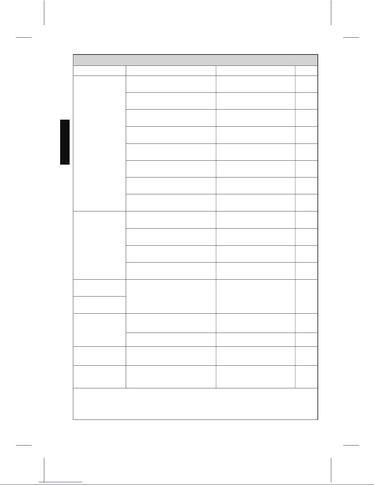
TROUBLESHOOTING
No water comes
from the flush
valve
Water does not
stop flowing
The discharge
quantity is too small
The discharge
quantity is too much
The flow rate is too
low
A red light in the
sensor window blinks
The main valve in water supply
line or the control stop is shut off
The connector is not
connected
The surface of the glass in front
of the infrared sensor is dirty
The glass is broken
There is a reflective surface in
front of the sensor
The infrared sensor or the
solenoid is out of order
The small holes in the solenoid
diaphragm are clogged
Hydropower generator clogged
The small hole in the piston is
clogged. (not for TEU*UA(R)(X))
The sealing area of the piston is
dirty. (not for TEU*UA(R)(X))
The sealing area of the solenoid
diaphragm is dirty.
The screw of the control stop or
the screw of the piston valve are
not adjusted properly
Water supply pressure is too low.
(below rated minimum pressure)
The control stop is not open enough.
The flow rate is too
high
The control stop is not adjusted
properly.
The battery is weak.
Open the main valve or the
control stop
Connect the wire
Clean the surface of the
glass
Contact distributor for
replacement
Remove the reflective
surface from the sensor
Contact distributor for
replacement
Clean the small hole in the
diaphragm and filter
Service Hydropower
Generator
Clean the small hole in the
piston
Clean the sealing area of
the piston
Clean the sealing area of
the diaphragm and filter
Adjust the discharge quantity
by the screw of the control
stop and the screw of the
piston valve
Consult with a plumbing
contractor
Adjust the control stop properly
Adjust the control stop
properly.
Check voltage with multimeter,
if below 2.6 V, contact TOTO
for replacement battery.
-
-
-
-
19
18
18
17
18
17
-
17
Piston U-packing damaged.
(not for TEU*UA(R)(X))
Inspect & replace if
necessary
18
-
18
18
18
Ref.Page
Suggested ActionPossible Cause
NOTE: Do not dismantle parts of the flush valve which are not specified in the
troubleshooting guide.
If you need further assistance, please call TOTO Tech Support at (888) 295-8134.
Problem
ENGLISH
Page 17

ENGLISH
17
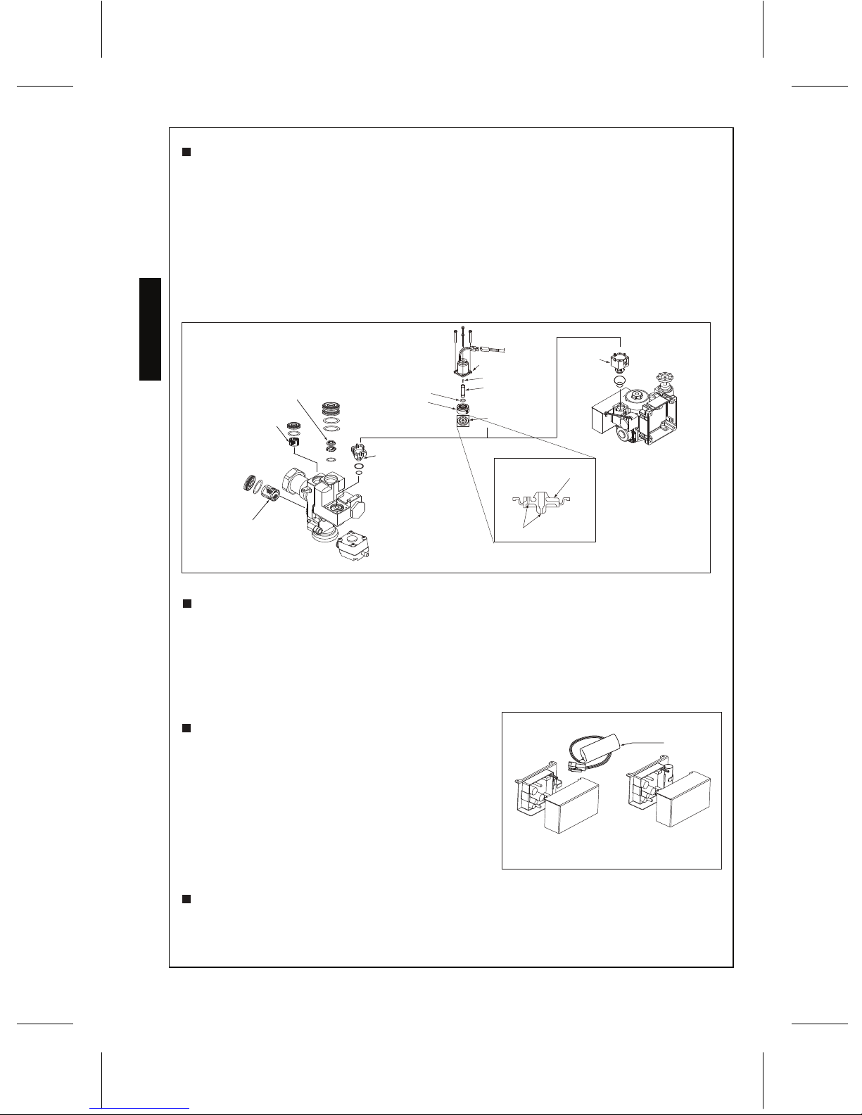
DISASSEMBLY
CLEANING PISTON ASSEMBLY
Control stop
Large cover
Small cover
Sealing Area
Small Hole
Filter
Piston U-Packing
Control stop
Supplied
hex wrench
Supplied
hex wrench
If the whole valve needs to be
removed from the water supply for
servicing, please be aware of the
cautions below:
1. Be careful not to lose or tear the
friction washer at the outlet
connection to the vacuum breaker
tube nut. To maintain a proper seal,
replace the washer if necessary.
2. Be careful when re-installing the
valve to the water supply to avoid
pinching the o-ring.
1. Turn the screw of the control stop
clockwise to turn off the water.
2. Take out the piston assembly.
3. Check the small hole in the piston to
see if it is clogged with debris, insert
a small wire to unclog hole.
4. Check the filter to see if it is
clogged with debris and gently
brush it to clean.
5. Check the sealing area of the piston
and clean it if it is dirty.
6. Check the U-Packing for cracks or
damage.
Page 18
ENGLISH
18
CLEANING DIAPHRAGM AND FILTER
BATTERY REPLACEMENT
ADJUSTMENT OF THE FLOW RATE
Diaphragm
Filter
Solenoid
O-ring
Plunger
Cap
Sensor unit
TEU2UA(R)(X) and TEU3UA(R)(X)
Flow regulator
Filter
Filter
Filter
Battery
1. Turn the screw on the control stop clockwise to turn off the water.
2. Disconnect the solenoid.
3. Remove the solenoid and take out the diaphragm.
4. Check the small holes and sealing.
NOTE: See this page below for disassembly.
NOTE: Do not stretch or alter the shape of the spring in the solenoid valve in any way. It
will void the warranty.
1. Make sure that the batteries are properly placed and wires are connected.
2. With water supply turned off, place your hand in front of the sensor for 6 seconds
3. Remove and listen for a “click” sound after 3 seconds. This indicates the solenoid
plunger has been activated.
A special lithium back-up battery is used. Replace
only with the included TOTO back up battery. If a red
light in the sensor window blinks with the cycle of
4 seconds, it is time to replace the battery.
1. Remove the old battery.
2. Set the new battery at the proper position.
1. Adjust the flow rate by the turning screw on the control stop.
2. Turn the screw to the right to decrease the flow rate and turn to the left to increase.
CHECKING SOLENOID
Spring
Diaphragm
Sealing area
Small holes
Page 19
19
THE DETECTION RANGE
Infrared sensor
The detection range of the infrared sensor is set at the factory and does not need further
adjustment.
Another infrared sensor.
PRECAUTION
PRECAUTION
DO NOT place the infrared sensor
of one Flush Valve so that it
is in line with the sensor of
another Flush Valve sensor.
DO NOT place the infrared sensor in
front of a mirror, stainless steel wall,
or other highly reflective surface.
Infrared sensor of the automatic
Flush Valve.
Infrared sensor of the automatic
Flush Valve.
Mirror, stainless steel wall or other
highly reflective surface.
NOTE: In some cases, the valve may not
detect a user if the toilet seat is left
in an upright position. This can be
due to the rough-in dimension or
gap of the open front commercial
seat. Please lower the seat or
arrange with a TOTO or other
plumbing contractor to change the
height of the valve.
The sensor can have trouble
detecting users wearing black
clothes in some conditions.
ENGLISH
33-1/2"
(850mm)
15°
Max 19-11/16”
(Max 500mm)
Page 20
20
WARRANTY
1. TOTO warrants its electronic flush valves, faucets and soap dispensers (“Product”) to be free from defects in
materials and workmanship during normal use when properly installed and serviced, for a period of three (3) years
from date of purchase. This limited warranty is extended only to the ORIGINAL PURCHASER of the Product and is
not transferable to any third party, including but not limited to any subsequent purchaser or owner of the Product.
This warranty applies only to TOTO Product purchased and installed in North, Central and South America.
2. TOTO’s obligations under this warranty are limited to repair, replacement or other appropriate adjustment, at
TOTO’s option, of the Product or parts found to be defective in normal use, provided that such Product was properly
snoitcepsni hcus ekam ot thgir eht sevreser OTOT .snoitcurtsni htiw ecnadrocca ni decivres dna desu ,dellatsni
ni strap ro robal rof egrahc ton lliw OTOT .tcefed eht fo esuac eht enimreted ot redro ni yrassecen eb yam
connection with warranty repairs or replacements. TOTO is not responsible for the cost of removal, return and/or
reinstallation of the Product.
5. THIS WARRANTY GIVES YOU SPECIFIC LEGAL RIGHTS. YOU MAY HAVE OTHER RIGHTS WHICH VARY
FROM STATE TO STATE, PROVINCE TO PROVINCE OR COUNTRY TO COUNTRY.
6. To obtain warranty repair service under this warranty, you must take the Product or deliver it prepaid to a TOTO
service facility together with proof of purchase (original sales receipt) and a letter stating the problem, or contact
a TOTO distributor or products service contractor, or write directly to TOTO U.S.A., INC., 1155 Southern Road,
Morrow, GA 30260 (888) 295 8134 or (678) 466-1300, if outside the U.S.A. If, because of the size of the Product
or nature of the defect, the Product cannot be returned to TOTO, receipt by TOTO of written notice of the defect
esoohc yam OTOT ,esac hcus nI .yreviled etutitsnoc llahs )tpiecer selas lanigiro( esahcrup fo foorp htiw rehtegot
to repair the Product at the purchaser’s location or pay to transport the Product to a service facility.
THIS WRITTEN WARRANTY IS THE ONLY WARRANTY MADE BY TOTO. REPAIR, REPLACEMENT OR OTHER APPROPRIATE
ADJUSTMENT AS PROVIDED UNDER THIS WARRANTY SHALL BE THE EXCLUSIVE REMEDY AVAILABLE TO THE ORIGINAL
PURCHASER. TOTO SHALL NOT BE RESPONSIBLE FOR LOSS OF THE PRODUCT OR FOR OTHER INCIDENTAL, SPECIAL
OR CONSEQUENTIAL DAMAGES OR EXPENSES INCURRED BY THE ORIGINAL PURCHASER, OR FOR LABOR OR OTHER
COSTS DUE TO INSTALLATION OR REMOVAL, OR COSTS OF REPAIRS BY OTHERS, OR FOR ANY OTHER EXPENSE NOT
SPECIFICALLY STATED ABOVE. IN NO EVENT WILL TOTO’S RESPONSIBI
LITY EXCEED THE PURCHASE PRICE OF THE
PRODUCT. EXCEPT TO THE EXTENT PROHIBITED BY APPLICABLE LAW, ANY IMPLIED WARRANTIES, INCLUDING THAT
OF MERCHANTABILITY OR FITNESS FOR USE OR FOR A PARTICULAR PURPOSE, ARE EXPRESSLY DISCLAIMED. SOME
STATES DO NOT ALLOW LIMITATIONS ON HOW LONG AN IMPLIED WARRANTY LASTS, OR THE EXCLUSION OR
LIMITATION OF INCIDENTAL OR CONSEQUENTIAL DAMAGES, SO THE ABOVE LIMITATION AND EXCLUSION MAY NOT
APPLY TO YOU.
3. This warranty does not apply to the following items:
a. Damage or loss sustained in a natural calamity such as fire, earthquake, flood, thunder, electrical storm, etc.
b. Damage or loss resulting from any accident, unreasonable use, misuse, abuse, negligence, or improper
care, cleaning, or maintenance of the Product.
c. Damage or loss resulting from sediments or foreign matter contained in a liquid soap system.
ro/dna hsrah a ni tcudorP eht fo noitallatsni morf ro noitallatsni reporpmi morf gnitluser ssol ro egamaD .d
hazardous environment, or improper removal, repair or modification of the Product.
e. Damage or loss resulting from electrical surges or lightning strikes or other acts which are not the fault of
TOTO or which the Product is not specified to tolerate.
f. Damage or loss resulting from normal and customary wear and tear, such as gloss reduction, scratching or
fading over time due to use, cleaning practices or water or atmospheric conditions, including but not limited
to, the use of bleach, alkali, acid cleaners, dry (powder) cleaners or any other abrasive cleaners or the use
of metal or nylon scrubbers.
ENGLISH
4. In order for this limited warranty to be valid, proof of purchase is required. TOTO encourages warranty registration
upon purchase to create a record of Product ownership at http://www.totousa.com is required. TOTO encourages
registration upon purchase and failure to register will not diminish you r limited warranty rights.
Page 21
INCLUÍA PARTES
Asegúrese que todas estas partes estén incluidas en su empacado*:
Montaje de cuerpo
del fluxômeter
Cubierta frontal
Bastidor base
Llave
hexagonal
Etiqueta de aviso
(TEU2UA(R)(X) sólo)
Tornillos hexagonal
es a prueba
de vandalismo
Cubierta Gran Cubierta Pequeña Cubierta Gran Cubierta Pequeña
(TEU3UA(R)(X) sólo)
Tubo rompedor
de vacìo
Llave de paso
Tubo de descarga
Tornillos
Cables de conexión
Sólo para pequeña cubierta
ESPAÑOL
21
ÍNDICE
¡Gracias por elegir TOTO!......................................................................................................................21
Incluía partes..............................................................................................................................................21
Herramientas que necesita......................................................................................................................22
Características................................................................................................................................ 22
Especificaciones........................................................................................................................ 23
Información técnica..................................................................................................................................24
Advertencias....................................................................................
............................... ......................25
Antes de la instalación...............................................................................................................................25
Procedimiento de instalación...................................................................................................................26
Prueba de funcionamiento......................................................................................................................33
Después de la instalación.........................................................................................................................34
Uso de l fluxómetro .. .................................................................................................................................34
Resolución de problemas........................................................................................................ ................35
Garantía........................................................................................................................................ 39
Bosquejo....................................................................................................................................................78
Especificaciones de Agua Reclamada.......................................................................................................................81
¡GRACIAS POR ELEGIR TOTO!
La misión de TOTO es dar al mundo estilos de vida más saludables, higiénicos y cómodos.
Diseñamos cada producto guiándonos por el principio del equilibrio entre forma y función.
Felicitaciones por su elección.
Arandela
Manual de
Instalación y
del Propietario
Mantenimiento periódico........................................................................................................................34
Cuidado y limpieza...................................................................................................................................34
Inicialización del producto.......................................................................................................................22
TEU3LA(X)11
TEU3UA(X)11
TEU2LA(X)21
TEU2UA(X)11
TEU3LA(X)21
TEU2LA(X)11
TET3GA33
TET3LA(X)33
TET3UA(X)33
TET2GA33
TET2LA(X)33
TET2UA(X)33
TET3GA31
TET3LA(X)31
TET3UA(X)31
TET2GA31
TET2LA(X)31
TET2UA(X)31
TET3GA32
TET3LA(X)32
TET3UA(X)32
TET2GA32
TET2LA(X)32
TET2UA(X)32
TEU3LA(X)12
TEU3UA(X)12
TEU2LA(X)12
TEU2UA(X)12
Page 22
ESPAÑOL
22
CARACTERÍSTICAS
Completamente Automático e Higiénico
El fluxómeter EcoPower utiliza un sensor infrarrojo para detectar al usuario que utiliza y acciona
el aparato, para proporcionar una descarga automática después de un breve retraso. No se
requiere ninguna operación manual para mejorar la experiencia de uso y la higiene del aparato.
Temporizador de Protección del Sistema
Cuando el inodoro no se utiliza durante 24 horas y 12 horas para urinario el temporizador
de protección da la orden al sistema para activar una descarga a fin de mantener el sello
de la trampa.
Funcionalidad Manual
El fluxómeter EcoPower tiene un botón de descarga manual para el mantenimiento y el uso de
emergencia.
Características Ecológicas
Conserva la Energía
Cada descarga activa un generador de energía hidráulica que genera energía eléctrica para la
siguiente descarga. (Consulte Acerca del Generador de Energía Hidráulica de TOTO
Conserva el Agua
Existen dos funciones que ayudan al fluxómeter EcoPower a conservar el agua:
Control Lógico Difuso
El fluxómeter EcoPower puede detectar con qué frecuencia y durante cuánto tiempo se ha
utilizado el aparato para entregar la cantidad correcta de agua. (Consulte Acerca de
Control Lógico Difuso , página 24)
Antidescarga Consecutiva
El fluxómeter EcoPower ofrece la prevención de descargas consecutivas que ahorran agua.
Después de una descarga, la válvula no se volverá a descargar de manera automática durante
10 segundos para los urinarios y 30 segundos para los inodoros.
HERRAMIENTAS QUE NECESITA
Los
fluxómeters
EcoPower de TOTO están diseñadas para funcionar durante 10 años, en
condiciones normales, sin uso mínimo requerido.
Destornillador (Phillips y Plano )
Llave ajustable
Llave de tubo
INICIALIZACIÓN DEL PRODUCTO
Tenga en cuenta que tardará al menos 5 minutos después de conectar la batería para que la
electrónica se inialice.
Este retraso es una parte normal del inicio
Después de aproximadamente 30 segundos, el LED del sensor comenzará a parpadear en
intervalos de 4 segundos hasta que finalice la inicialización.
Gracias por elegir la última innovación en productos EcoPower de bajo consumo de energía.
Tenga en cuenta a continuación la duración del tiempo necesario para inicializar la electrónica.
, página 24)
Page 23
ESPAÑOL
23
32-104˚F (0-40˚C)
34-104˚F (1-40˚C)
1"NPT 3/4"NPT
1-1/4"NPSM
1-1/2"NPSM
7 psi (48kPa)
Tipo de fluxômetro Mingitorio de baldeo
Número de modelo
Tiempo de detección
Figura
Temperatura ambiente
Temperatura de agua
Entrada de parada de control
Presión de
suministro de
agua
Presión de apagado
Volumen
Tipo de Inodoro/Urinario
Protección del sello
de la trampa
Inodoros Urinarios
Mínimo
Máximo*
35 psi (241kPa)
(Fluir)
15 psi (103 kPa)
125 psi (862kPa)
0.5 G (1.9L)
0.125 G (0.47L)
6 s
NOTA:
Cubierta
Gran
Cubierta
Pequeña
12-5/8" (H) ×14-3/16"(W)
(320mm(H) ×360mm(W) )
Dimensión de
la cubierta
Cubierta
Gran
Cubierta
Pequeña
4-23/32" (H) ×4-23/32"(W)
(120mm(H) ×120mm(W) )
Rango de detección de frente Dentro de 33-1/2" (850mm)
(Estática)
Consulte al fabricante del aparato para la presión mínima requerida para la válvula.
* No se recomiendan las presiones de agua de más de 80 psi para la mayoría de los accesorios de plomería.
ESPECIFICACIONES
Entrée de valve de chasse
essahc ed evlav ed eitroS
Descarga automática cada 24 horas
de no utilización
Descarga automática cada 12 horas
de no utilización
Cubierta
Gran
Cubierta
Pequeña
1.6 G (6L)
1.0 G (3.8L)1.28 G (4.8L)
TET2GAR
TET3GAR
TEU2LA(R)(X)
TEU3LA(R)(X)
TEU2UA(R)(X)
TEU3UA(R)(X)
TET2UA(R)(X)
TET3UA(R)(X)
TET2LA(R)(X)
TET3LA(R)(X)
Page 24
ESPAÑOL
24
Acerca de Control Lógico Difuso (TEU1GAR)
Tiempos Cortos de Inactividad Tiempos Largos de Inactividad
Menos
Típica
Largo Período de Uso Corto Período de Uso
Acerca del Generador de Energía Hidráulica
1)
3)
2)
Sensor
Controlador
Pistón
Línea de suministro de agua
Fluxómetro
Resorte
Turbina
Cubierta
Sensor
Controlador
Fluxómetro
Línea de suministro de agua
Cubierta
Turbina
Resorte
INFORMACIÓN TÉCNICA
El flujo de agua hace que la turbina gire en el generador de energía. Este proceso genera energía
eléctrica y permite que funcione el fluxómetro automática. Ver ilustración 1 a continuación.
La función de Control Lógico Difuso ajusta de manera automática la descarga de agua de
acuerdo con la frecuencia y la duración de uso (ver ilustración 2 y ilustración 3).
Típica
Para los tiempos cortos de inactividad, el sistema asume
el uso frecuente del urinario y el fluxómetro
suelta menos agua.
Ejemplos de uso frecuente sería durante una pausa para
almorzar o un intermedio en una sala de cine.
Un corto período de uso
indica que puede haber
menos para descarga, lo que
requiere que el
fluxómetro libere menos
agua para de descarga.
Para tiempos largos de inactividad, el
sistema asume un uso poco frecuente, y
hace que el fluxómetro
entregue una cantidad típica de agua
para una limpieza a fondo.
Ejemplos de uso poco frecuente sería
después de las horas en la oficina o un día
lento en el parque day.
El sistema Control Lógico
Difuso del sistema
determina la frecuencia
de uso por el tiempo
de inactividad del
urinario y hace que la
fluxómetro
suelte agua en un
patrón óptimo de
descarga.
El sistema Control Lógico
Difuso predice la
cantidad de agua de
descarga necesaria, con
base en la duración de
uso del usuario.
Un largo período de uso indica
que puede haber más para
descargar, lo que requiere que el
fluxómetro suministre una
cantidad típica de agua de
descarga para una descarga a
fondo.
ill. 2 Frecuencia de Uso
ill. 3 Duración de Uso
ill. 1 Generador de Energía Hidráulica
Una turbina gira para
generar energía
eléctrica.
La energía eléctrica se
almacena en un
condensador.
El fluxómetro
automática utiliza la
energía cargada.
Menos Menos Menos Menos
Menos
Típica
1)
3)
2)
Una turbina gira para
generar energía
eléctrica.
La energía eléctrica se
almacena en un
condensador.
El fluxómetro
automática utiliza la
energía cargada.
Menos
TET2LA(R)(X)
TET2GAR
TET3LA(R)(X)
TET3GAR
TEU2LA(R)(X)
TEU3LA(R)(X)
TEU2UA(R)(X)
TEU3UA(R)(X)
TET2UA(R)(X)
TET3UA(R)(X)
Page 25
ESPAÑOL
25
ANTES DE LA INSTALACIÓN
ADVERTENCIAS
Importante: La instalación de la plomería debe hacerse de acuerdo con los códigos y
reglamentos aplicables. Las líneas de suministro de agua deben dimensionarse para
proporcionar un volumen adecuado de agua para cada aparato. Descargue todas las líneas
de agua antes de utilizarlas.
Antes de instalar su fluxómetro, instale los elementos que se enumeran a
continuación:
Accesorio Inodoro/Accesorio Urinario
Línea de drenaje
Línea de suministro de agua
La tubería de suministro de estos dispositivos debe estar anclada firmemente a la estructura
del edificio para evitar que el dispositivo instalado se mueva durante el uso. Tenga cuidado al
instalar el dispositivo para evitar estropear la superficie expuesta. Importante: Limpie todo el
aire de las líneas de suministro antes de conectar la válvula de descarga al recipiente. El aire
atrapado en las líneas de suministro puede romper la china.
Tenga cuidado de no dañar la superficie del sensor infrarrojo.
Para el fluxómetro del Inodoro:
El fluxómetro del inodoro puede no funcionar si el asiento y/o la tapa del inodoro
se dejan en posición vertical, ya que puede bloquear el sensor.
Para el fluxómetro del Urinario:
El fluxómetro del urinario está diseñada para un rendimiento óptimo con urinarios
de lavado para un rendimiento óptimo, pero se puede sustituir un urinario de chorro. No se
recomiendan los urinarios Blowout.
Ver rango de detección del sensor infrarrojo en p. 38.
Para evitar el mal funcionamiento del
fluxômeter
, no instale un pasamanos o cualquier otro
objeto dentro del rango de detección del sensor. No instale el fluxómetro donde el
sensor esté al frente de un espejo, una pared de acero inoxidable, otras superficies altamente
reflectantes u otro sensor infrarrojo.
Lea y cumpla estas instrucciones. No hacerlo podría dar lugar a lesiones personales o daños
materiales.
Nunca salpique agua en el controlador. El
fluxómetro
EcoPower es un aparato eléctrico.
Riesgo de mal funcionamiento del producto.
No golpee ni patee el
fluxómetro
EcoPower. Riesgo de mal funcionamiento o fuga de agua.
No utilice el
fluxómetro
EcoPower a temperaturas superiores a las permitidas por los
códigos locales o las especificaciones del producto. Riesgo de mal funcionamiento del
producto.
No coloque el
fluxómetro
EcoPower en una habitación con alta humedad, como el área
de la ducha o en la sauna. Riesgo de mal funcionamiento del producto.
Nunca intente desmontar, volver a montar, reparar o modificar el
No utilice el interrruptor de vacío o la llave de paso con válvula de descarga de agua saneada.
No utilice sellantes de tubería o productos a base de petróleo, hacerlo podría dañar el
producto y causar daños por agua.
fluxómetro
EcoPower a
menos que usted sea un profesional. Riesgo de mal funcionamiento del producto y
descargas eléctricas.
Para la válvula de descarga de agua saneada:
Utilice únicamente el interruptor de vacío y la llave angular de agua saneada.
Los fluxómetros de inodoro y urinario no son intercambiables, compruebe el número de
modelo en la etiqueta para asegurarse de que tiene el tipo correcto. Los números de
modelo del fluxómetro del inodoro comienzan con 'TET' y los modelos del fluxómetro
urinario empiezan con 'TEU'.
Page 26
Tubería del suministro izquierda
1” NPT (inodoro), 3/4” (urinario)
4-3/4” ± 1/2”
(120 ± 13mm)
Sensor
3-7/16” (87mm)
** 11-15/16”
(303mm)
16” (406mm)
3/4” (19mm)
Montant
Escoplo superior (inodoro)
Ø2-3/16” (Ø56mm) hole
Escoplo posterior (urinario)
Ø1-5/16” (Ø33mm) hole
Escoplo posterior (inodoro)
Ø2-3/16” (Ø56mm) hole
11” (279mm)
CL de sensor
* X”
** 13-1/2”
(343mm)
* 14-3/4” ‡
desde la parte
superior del inodoro
Escoplo superior (urinario)
Ø1-1/2” (Ø38mm) hole
* X”, ‡ = Se requiere al menos 5" de espacio libre desde el sensor hasta la punta
del asiento del inodoro o hasta la parte superior de la barra de apoyo para
evitar una detección falsa. Para la instalación del inodoro.
** Abertura en la pared
Tubería del suministro derecho
1” NPT (inodoro), 3/4” (urinario)
ESPAÑOL
26
PROCEDIMIENTO DE INSTALACIÓN — GRAN CUBIERTA
NOTA:
Bastidor base
Placa
ajustable
Agujero ajustable
Coloque la llave de paso
NOTA:
Para el agua saneada, no utilice el interruptor
de vacío estándar o la llave de paso.
NOTA:
No utilice sellantes de tubería o productos
a base de petróleo
antes de instalar el bastidor
base. Debe utilizarse
compuestos de sellado de
rosca solo en roscas NPT
macho.
5. Fije el bastidor base a los pernos con
cuatro tornillos (preparado en el lugar)
después de ajustarlo. ( A )
6. Asegure el bastidor base con cuatro
tornillos en la placa ajustable. ( B )
Para el uso con el suministro de agua
izquierda, extraiga el controlador y
vuelva a montarlo al lado opuesto
del cuerpo de la
fluxómetro.
Despegar Volver al montar
Cuerpo de la fluxómeter
Proteger los conexións de cables,
manteniéndolos dentro de la
caja del controlador.
1. Determine la ubicación de la
instalación de los pernos y la
tubería del suministro de agua en
relación con la posición del
orificio del aparato.
2. Si es necesario, deslice un adaptador de soldadura de rosca en la
tubería del suministro de agua.
3. Coloque la llave de paso a la
tubería.
4. Perfore un agujero guía para la
tubería de descarga en la pared.
N
O
U
T
I
L
I
C
E
P
R
O
D
U
C
T
O
S
A
B
A
S
E
D
E
P
E
T
R
Ó
L
E
O
¡
A
T
E
N
C
I
Ó
N
!
Page 27

TET2LA(X)32, TET2GA32, TET2UA(X)32
TEU2LA(X)12, TEU2UA(X)12
TET2LA(X)31, TET2UA(X)31
TET2GA31
TET2LA(X)33, TET2UA(X)33
TET2GA33
TEU2LA(X)11, TEU2LA(X)21
TEU2UA(X)11
Inodoro o urinario
Pared
6~6-1/2”
(152~165mm)
1-1/2” (38mm)
o 3/4” (19mm)
1-1/2”
(38mm)
5”
(127mm)
2-1/4”~2-3/4”
(57~70mm)
3-3/4”~4-7/8”
(95~124mm)
3-3/4”~4-7/8”
(95~124mm)
Escoplo superior
Escoplo posterior
(Pared)
3”
(76mm)
Inodoro
3-3/4”~4-7/8”
(95~124mm)
3-3/4”~4-7/8”
(95~124mm)
Urinario
Escoplo posterior
(Piso)
Inodoro
1-1/2”
(38mm)
1-1/4” (32mm)
o 3/4” (19mm)
7” (178mm) espacio
mínimo en la pared
Pared
Pared
Pared
7” (178mm) espacio
mínimo en la pared
7” (178mm) espacio
mínimo en la pared
7” (178mm) espacio
mínimo en la pared
ESPAÑOL
27
7. Pase el tubo de desagüe y el
regulador de vacío a través del
agujero guía (Paso 3) y móntelos en la
taza.
8. Si es necesario, corte el tubo
regulador de vacío a la longitud
apropiada.
9. Asegúrese de que la junta tórica encaja
en la ranura en el extremo del tubo de
desagüe del fluxómetro.
NOTA: Tenga cuidado de no dañar la junta
tórica al insertar el tubo de desagüe
en la llave de paso. Si se necesita
lubricación, moje la junta tórica con
agua.
10. Conecte el fluxómetro con la
llave de paso y el tubo regulador
de vacío.
Junta
tórica
PROCEDIMIENTO DE INSTALACIÓN — GRAN CUBIERTA
Anillo de
retención
Page 28

ESPAÑOL
28
Llave hexagonal
Llave de paso
NOTA:
Los
fluxómetros
están predefinidas
para volumen l de desgarga como está
marcado en la caja de la válvula. Esto
no requiere ajuste para la variación en la
presión de agua dentro de su rango de
operación.
15. Para colocar el fluxómetro en
su funcionamiento correcto, abra la
llave de paso por completo y active la
fluxómetro varias ocasiones.
16. En el caso de flujo excesivo debido a
la alta presión del agua, ajuste gradu almente la llave de paso hacia la
derecha (hacia la posición cerrada)
hasta que haya un flujo de agua
adecuado en el aparato.
La llave de paso nunca deberá
abrirse hasta el punto donde el
flujo del fluxómetro
excede la capacidad de flujo del
aparato. En caso de una falla de
la válvula, el agua debe
desbordarse del aparato.
17. Ajuste los tornillos de la cubierta
frontal en el bastidor de la base firme
mente con la llave hexagonal.
Asegúrese de que no haya ningún
cable, alambre o cadena atrapados
entre la cubierta frontal y el bastidor
base.
12. Conecte los cables del sensor infrarrojo
y el controlador con el cable de
conexión.
13. Conecte los cables del botón de descarga
manual
y del controlador con el cable de
conexión.
PROCEDIMIENTO DE INSTALACIÓN — GRAN CUBIERTA
Abierto
Cable de conexión
(botón)
Cable de conexión
(sensor)
NOTA:
Tenga en cuenta que tardará al menos
5 minutos después de conectar la batería
para que la electrónica se inialice. Después
de aproximadamente 30 segundos, el LED
del sensor comenzará a parpadear en
intervalos de 4 segundos hasta que finalice
la inicialización.
14. Antes de abrir el suministro de agua, asegúrese
de que todas las fugas de agua se eliminan al
ajustar todas las conexiones de la tubería.
NOTA: Si por alguna razón es necesario retirar la
llave de paso, asegúrese de que el agua está
cerrada en la válvula de suministro principal.
Batería
Controlador
Cable de conexión
11. Conecte el cable del batería con el cable de conexión.
Page 29

4 x Ø5/16" (Ø8mm) agujero
Tubería del suministro izquierda
1”NPT (inodoro), 3/4” (urinario)
Tubería del suministro derecho
1”NPT (inodoro), 3/4” (urinario)
Escopolo superior (inodoro)
Ø2-3/16” (Ø56 mm) agujero
Escoplo posterior (urinario)
Ø1-5/16” (Ø33 mm) agujero
Escoplo posterior (inodoro)
Ø2-3/16” (Ø55 mm) agujero
X”
1-1/4” (31 mm)
CL of sensor
** 3-11/16”
(94mm)
11” (279mm)
16” (406mm)
** 3-11/16”
(94 mm)
* X”, ‡ = Se requiere al menos 5" de espacio libre desde el sensor hasta la punta del asiento
del inodoro o hasta la parte superior de la barra de apoyo para evitar una detección falsa.
Para la instalación del inodoro.
** Abertura en la pared
4-3/4” ± 1/2”
(120 ± 13mm)
Escopolo superior (urinario)
Ø1-5/16” (Ø33 mm) agujero
ESPAÑOL
29
PROCEDIMIENTO DE INSTALACIÓN — CUBIERTA PEQUEÑA
NOTA:
Para utilizar con un suministro de agua
izquierda, separe el controlador y vuelva
a montarlo al lado opuesto del cuerpo
de la válvula.
5. Asegure el bastidor a la pared con dos tornillos del
bastidor base. Vea otras opciones de instalación del
bastidor base en la página siguiente.
El espesor de la pared debe ser de 1/2"
(13 mm) como mínimo y 1-3/8" (35 mm)
como máximo. Si el grosor de la pared es
menor que
1/2" (13 mm), adjunte un bastidor
de madera detrás de la pared.
1. Determine la ubicación de la
instalación de tubería del
suministro de agua
3. Coloque la llave de paso a la
tubería.
4. Perfore un agujero guía para la
tubería de descarga en la
pared.
NOTA: Debe utilizarse compuestos
de sellado de rosca solo
en roscas NPT macho.
Extraer
Volver a montar
Proteger los conexións de cables,
manteniéndolos dentro de la
caja del controlador.
2. Si es necesario, deslice un
adaptador de soldadura de
rosca en la tubería del
suministro de agua.
Page 30

30
Opción 5A (con tirante)
Max.1”(25mm)
Min.1-3/8”(35mm)
Tornillos
Tirante
Tirante
Pestaña
Tirante
Opción 5B (para pared de hormigón)
Tornillos
Mortero
Pestaña
1. Retire todas las pestañas al lado del bastidor base.
2. Fije el bastidor base al tirante con 4 tornillos
(preparado en el lugar).
1. Recorte un lugar para la cubierta en la pared.
2. Retire todas las pestañas al lado del bastidor
base antes de la instalación.
3. Fijar el bastidor base en su lugar con un
mortero.
4. Asegure el bastidor base con 4 tornillos
(preparado en el lugar), si es necesario.
Otras opciones de instalación del bastidor base
PROCEDIMIENTO DE INSTALACIÓN — CUBIERTA PEQUEÑA
ESPAÑOL
4-1/3”
(110mm)
4-1/3”
(110mm)
3/4”
(19mm)
Page 31

TET3LA(X)32, TET3GA32, TET3UA(X)32
TEU3LA(X)12, TEU3UA(X)12
TET3LA(X)31, TET3UA(X)31
TET3GA31
Inodoro o Urinario
6~6-1/2”
(152~165mm)
1-1/2” (38mm)
o 3/4” (19mm)
1-1/2”
(38mm)
5”
(127mm)
2-1/4”~2-3/4”
(57~70mm)
3-3/4”~4-7/8”
(95~124mm)
3-3/4”~4-7/8”
(95~124mm)
Raccord supérieure
Escoplo posterior
(Pared)
3”
(76mm)
Inodoro
TET3LA(X)33, TET3UA(X)33
TET3GA33
TEU3LA(X)11, TEU3LA(X)21
TEU3UA(X)11
3-3/4”~4-7/8”
(95~124mm)
Urinario
Escoplo posterior (Piso)
Inodoro
1-1/2”
(38mm)
1-1/4” (32mm)
o 3/4” (19mm)
Pared
Pared
Pared
Pared
7” (178mm) espacio mínimo
en la pared conun panel de
acceso de 12” x 12” mínimo
o corredor de acceso posterior
3-3/4”~4-7/8”
(95~124mm)
7” (178mm) espacio mínimo
en la pared conun panel de
acceso de 12” x 12” mínimo
o corredor de acceso posterior
7” (178mm) espacio mínimo
en la pared conun panel de
acceso de 12” x 12” mínimo
o corredor de acceso posterior
7” (178mm) espacio mínimo
en la pared conun panel de
acceso de 12” x 12” mínimo
o corredor de acceso posterior
31
Anillo de
retención
Junta
tórica
8. Asegúrese de que la junta tórica encaja
en la ranura en el extremo del tubo de
desagüe del fluxómetro.
9. Tenga cuidado de no dañar la junta
tórica al insertar el tubo de desagüe en
la llave de paso. Si se necesita lubricación, moje la junta tórica con agua.
6. Pase el tubo de cola y el tubo
regulador a través del agujero
guía y móntelos en la taza.
7. Si es necesario, corte el tubo
regulador de vacío de presión
a la longitud apropiada.
10. Conecte el fluxómetro con la llave
de paso y el tubo regulador de vacío.
11. Ajuste la tuerca de unión con una llave lo
suficiente para evitar cualquier fuga de agua.
PROCEDIMIENTO DE INSTALACIÓN — CUBIERTA PEQUEÑA
ESPAÑOL
Page 32

E P Ñ L
32
Llave hexagonal
Arandela
Tornillo
12. Conecte el cable de la batería con el
controlador y coloque la batería en su
posición.
13. Coloque la cubierta frontal a la
pared con arandelas entre la cubierta
y la pared y los tornillos a prueba
de vandalismo.
16. Antes de abrir el suministro de agua,
asegúrese de que todas las fugas de
agua se eliminan al ajustar todas las
conexiones de la tubería.
Si por alguna razón es necesario retirar la
llave de paso, asegúrese de que el agua
está cerrada en la válvula de suministro
principal.
17. Ajuste los tornillos de la cubierta frontal
en el bastidor de la base firmemente con
la llave hexagonal.
Asegúrese de que no haya ningún
cable, alambre o cadena atrapados
entre la cubierta frontal y el bastidor base.
14. Conecte los cables del sensor infrarrojo
y el controlador con el cable de conexión.
15. Conecte los cables del botón de descarga
manual y del controlador con el cable de
conexión.
PROCEDIMIENTO DE INSTALACIÓN — CUBIERTA PEQUEÑA
ESPAÑOL
Cable de conexión
(botón)
Cable de conexión
(sensor)
Batería
Controlador
Cable de conexión
NOTA:
Se tardará 5 minutos después de conectar
la batería para que la electrónica se
inicialice. Después de aproximadamente
30 segundos, el LED del sensor
parpadeará en intervalos de 4 segundos
hasta que finalice la inicialización.
NOTA:
Page 33

33
ADVERTENCIA: La llave de paso nunca deberá abrirse hasta el punto donde flujo del
fluxómetro excede la capacidad de flujo del aparato. En caso de una
falla de la válvula, el agua no debe desbordarse del aparato.
Llave de paso
Abierto
El fluxómetro están predefinidas para el
volumen del aparato como está marcado en la caja
de la válvula. El fluxómetro no requiere ajuste para la
variación en la presión de agua dentro de su rango
de operación.
18. Para establecer el funcionamiento correcto de la
fluxómetro, utilice el tornillo de ajuste
para abrir la llave de paso por completo.
19. Active el fluxómetro varias veces.
20. En caso de flujo excesivo, ajuste gradualmente la
llave de paso hacia la derecha hasta la posición
cerrada utilizando el tornillo de ajuste, hasta que
haya un flujo de agua adecuado en el aparato.
PROCEDIMIENTO DE INSTALACIÓN — CUBIERTA PEQUEÑA
PRUEBA DE FUNCIONAMIENTO
ESPAÑOL
1. Para Inodoros: Siéntese en el asiento del inodoro.
Para Urinarios Sitúese a menos de dos pies de distancia del frente del fluxómetro.
2. Quédese ahí durante 6 segundos o más y luego deje el asiento del inodoro o el urinario. El
fluxómetro debe activarse automáticamente en 3 segundos por el inodoro y immediamente
por el urinario.
3. Pulse el botón manual de descarga durante 2 segundos y asegúrese de que la válvula se
descarga correctamente y que la luz roja del sensor está encendida. Para corregir para el
desbordamiento de el fluxómetro urinario, ajustar el llave de paso de las agujas del reloj.
4. Vuelva a revisar todas las conexiones de las tuberías para buscar fugas de agua. Si el
fluxómetro no funciona correctamente después de la prueba de funcionamiento, consulte la
sección Solución de problemas en la p.35.
Se tardará 5 minutos después de conectar la batería para que la electrónica se inicialice.
Después de aproximadamente 30 segundos, el LED del sensor parpadeará en intervalos de
4 segundos hasta que finalice la inicialización. Espere antes de iniciar la prueba de funcionamiento.
Page 34

Cuando el inodoro no se utiliza durante 24 horas (12 horas para urinario) el temporizador
de protección da la orden al sistema para activar una descarga a fin de mantener el sello
de la trampa.
34
MANTENIMIENTO PERIÓDICO
Revise su fluxómetro EcoPower al menos una vez al mes de acuerdo a estas
instrucciones para evitar el riesgo de daños a la propiedad.
Revise la tubería para ver si hay alguna fuga.
USO DEL FLUXÓMETRO
Sensor infrarrojo Descarga
Descarga cada 24/12 horas
Botón de descarga manual
El sensor infrarrojo detecta a un
usuario del inodoro o que está de
pie dentro de los 2 pies de
distancia (600 mm) del frente
del urinario.
Cuando el usuario permanece en el
lugar más de 6 segundos antes de salir,
el regulador le indica al equipo de
operación que active la Válvula de
Descarga después de 3 segundos de
retraso para inodoro o sin demora
para urinario.
Utilice el botón de descarga
manual para el mantenimiento
o las emergencias.
DESPUÉS DE LA INSTALACIÓN
ESPAÑOL
Después que la unidad del fluxómetro se ha instalado correctamente, explique a sus clientes
cómo utilizarla y dígales que sigan estas instrucciones:
1. No coloque ningún objeto delante de la ventana del sensor que podría obstruirlo y provocar
un mal funcionamiento.
2. En caso de algún problema, consulte la sección Solución de problemas en la p.35. Si usted
carece de los conocimientos necesarios requeridos o tiene dificultad para seguir las instrucciones de instalación, mantenimiento, reparaciones, solución de problemas o ajustes del
producto, no proceda sin la ayuda de una persona calificada para ayudarle.
CUIDADO Y LIMPIEZA
¡IMPORTANTE! No raye el sensor o placa frontal al limpiar el producto.
Evite utilizar cualquier material de limpieza que pueda rayar la superficie.
Nunca utilice polvo para pulir, detergente que incluya partículas corrosivas, thinners,
benceno, ácidos, detergentes alcalinos ni estropajos de nylon, ya que pueden dañar la
superficie.
Para limpiar la superficie con seguridad, límpiela con un trapo remojado en detergente para
trastes diluido y séquelo con otro trapo. Si esto no limpia adecuadamente la superficie,
límpiela con un detergente neutro y un trapo mojado.
Page 35

35
RESOLUCIÓN DE PROBLEMAS
Página
Acción SugeridaCausa Posible
No desmonte las piezas del fluxómetro que no se especifican en la guía de solución de problemas.
Si necesita más ayuda, por favor llame a TOTO Tech Support a (888) 295-8134.
Problemo
La presión de agua es demasiado baja
Limpie el agujero pequeño en
el pistón
-
37
36
37
36
37
36
37
37
37
37
El agua no deja
de fluir
Volumen
es demasiado
pequeño
Volumen
es demasiado
La velocidad del flujo
es demasiado baja
La velocidad del flujo
es demasiado alto
Una luz roja parpadea
en la ventana del
sensor
El sensor infrarrojo o el solenoide
está malogrado
Los pequeños agujeros en el diafragma
del solenoide están atascados
El generador de energía hidráulica
está atascado
El pequeño agujero en el pistón está
atascado. (no para TEU*UA(R)(X))
El área de sellado del pistón está
sucia. (no para TEU*UA(R)(X))
El área de sellado del diafragma del
solenoide está sucia.
El tornillo de la llave de paso no
está ajustado correctamente
La llave de paso no está abierta lo
suficiente
Inspeccione y reemplace si es
necesario
La batería tiene poca carga
Ajuste la llave de paso
correctamente
Consulte a un contratista de
plomería
Compruebe el voltaje con un
multímetro, si es inferior a 2.6 V,
llame a TOTO para una batería
de reemplazo.
Ajuste la llave de paso
correctamente
Contacte a su distribuidor para
obtener repuestos
Limpie el agujero pequeño en el
diafragma y en el filtro
Mantenimiento del generador de
energía hidráulica
Limpie el área de sellado
del pistón
Limpie el área de sellado del
diafragma y del filtro
Ajuste la cantidad
con el tornillo de la freno del
control
El empaque U del pistón está
dañado. (no para TEU*UA(R)(X))
La llave de paso no está abierta lo
suficiente
-
-
-
-
38
-
No sale agua de la
fluxómetro
La válvula principal en la línea de
suministro de agua o la freno del
control está cerrada
Uno o más cables no están conectados
La superficie del vidrio en frente del
sensor infrarrojo está sucia
El vidrio está roto
Hay una superficie reflectante en
frente del sensor
Contacte a su distribuidor para
obtener repuestos
Retire la superficie reflectante
frente al sensor
Limpie la superficie del vidrio
Revise todas las conexiones
de cable
Abra la válvula principal o la
llave de paso
ESPAÑOL
Page 36

36
ESPAÑOL
DESMONTAJE
LIMPIEZA DEL MONTAJE DEL PISTÓN Y DEL FILTRO
Llave de paso
Cubierta gran
Cubierta pequeño
Área de sellado
Agujero pequeño
Filtro
Empaque u
Llave de paso
Llave hexagonal
suministrada
Si necesita desmontar toda la válvula
del suministro de agua para darle
mantenimiento, tome las siguientes
precauciones:
1. Tenga cuidado de no perder o
romper la arandela de fricción en la
conexión de salida a la tuerca del
tubo regulador de vacío. Para
mantener un sellado adecuado,
reemplace la arandela si es necesario.
2. Al volver a instalar el fluxómetro al
suministro de agua, evite pellizcar la
junta tórica.
1. Gire el tornillo de la llave de paso
hacia la derecha para cerrar el agua.
2. Saque el montaje del pistón.
3. Revise el agujero pequeño en el
pistón para ver si está atascado con
desechos. Inserte un alambre
pequeño para destapar el agujero si
es necesario.
4. Revise el filtro para ver si está
atascado con desechos y cepille
suavemente para limpiar.
5. Revise el área de sellado del pistón
y límpiela si está sucia.
6. Revise el empaque u para buscar
fisuras o daños.
Llave hexagonal
suministrada
Tapa
Montaje del pistón
Montaje del pistón
Tapa
ESPAÑOL
Page 37

37
LIMPIEZA DEL DIAFRAGMA DEL FILTRO
Diafragma
Agujeros pequeños
Diafragma
Filtro
Solenoide
Junta tórica
Émbolo
Tapa
Unidad de sensor
TEU2UA(R)(X) y TEU3UA(R)(X)
Regulador
Filtro
Filtro
Filtro
Battería
1. Gire el tornillo de la llave de paso hacia la derecha para cerrar el agua.
2. Desconecte el solenoide.
3. Quite el solenoide y saque el diafragma. Luego, revise los agujeros pequeños y el área
de sellado.
NOTA: Ver a continuación para el desmontaje.
NOTA: No estire o altere la forma del resorte en el fluxómetro del solenoide de ninguna
manera. Se anulará la garantía.
1. Asegurarse de que las baterías están colocadas correctamente y que los cables están
conectados.
2. Con el suministro de agua cerrado, coloque su mano delante del sensor durante
6 segundos.
3. Retire y escuche un "clic" después de 3 segundos. Esto indica que el émbolo del solenoide
se ha activado.
-
REEMPLAZO DE LA BATERÍA
AJUSTE DEL FLUJO
1. Ajuste el flujo en la llave de paso.
2. Gire hacia la derecha para disminuir el flujo y gire a la izquierda
para aumentarlo.
Reemplace solo con la batería suministrada por
TOTO. Se utiliza una batería especial de litio de
respaldo.
Si una luz roja en la ventana del sensor parpadea
con el ciclo de 4 segundos, es hora de reemplazar
la batería.
1. Retire la batería vieja.
2. Coloque la batería nueva en la posición correcta.
Área de sellado
ESPAÑOL
MÉTODO DE REVISE EL SOLENOIDE
Resorte
Page 38

38
ES OL
Sensor infrarojo
RANGO DE DETECCIÓN
Sensor infrarrojo de la otra
fluxómetro
ADVERTENCIA
ADVERTENCIA
El rango de detección del sensor infrarrojo se ha fijado en la fábrica y no necesita ajuste
adicional.
NO coloque el sensor infrarrojo de
una fluxómetro de tal
manera que esté en línea con el
sensor de otra fluxómetro.
NO coloque el sensor infrarrojo
delante de un espejo.
NOTA: El fluxómetro puede no detectar a un
usuario si el asiento del inodoro se
deja en posición vertical. Esto puede
ser debido a la dimensión aproximada
o a la brecha del hueco del asiento
comercial frontal. Baje el asiento o
coordine con TOTO o otro contratista
de plomería para cambiar la altura de
el fluxómetro.
En algunos casos, el sensor puede
tener problemas para detectar a los
usuarios que usen ropa negra.
Sensor infrarrojo del fluxómetro Sensor infrarrojo del fluxómetro
Espejo, pared sin mancha de
acero y otra superficie altamente
reflectante
ESPAÑOL
33-1/2"
(850mm)
15°
Max 19-11/16”
(Max 500mm)
Page 39

39
GARANTÍA
1. TOTO garantiza que sus
grifos y dispensadores de jabón automáticos (“Producto”) no
tienen defectos en los materiales y mano de obra durante su uso normal, cuando son adecuadamente
instalados y cuidados, por un periodo de tres (3) años a partir de la fecha de compra. Esta garantía limitada se
extiende únicamente al COMPRADOR ORIGINAL del Producto y no es transferible a ninguna tercera persona,
incluyendo, pero sin limitarse a, cualquier comprador o dueño subsecuente del Producto. Esta garantía aplica
únicamente al Producto TOTO adquirido e instalado en América del Norte, Central y del Sur.
2. Las obligaciones de TOTO bajo esta garantía se limitan a reparar, reemplazar u otro ajuste adecuado, a elección
de TOTO, del Producto o partes que estén defectuosas con el uso normal, dado que dicho Producto haya sido
adecuadamen
te instalado, utilizado y cuidado de determinar la causa del defecto. TOTO no cobrará por el
trabajo o partes relacionados con las reparaciones o cambios de la ga-rantía. TOTO no es responsable por el
costo de remoción, devolución y/o reinstalación del Producto.
3. Esta garantía no aplica a los siguientes puntos:
a. Daño o pérdida ocurridos en una calamidad natural, tal como un incendio, terremoto, inundación, truenos,
tormenta eléctrica, etc.
b. Daño o pérdida resultado de cualquier accidente, uso no razonable, mal uso, abuso, negligencia o cuidado,
limpieza o manten-imiento inadecuado del Producto.
c. Daño o pérdida resultado de sedimentos o materia extraña contenidos en un sistema de aguas.
d. Daño o pérdida resultado de una instalación inadecuada o de la instalación del Producto en un ambiente
e. Daño o pérdida resultado de sobrecarga eléctrica o rayos u otros actos que no sean culpa de TOTO o que
f. Daño o pérdida resultado del desgaste normal y acostumbrado, tal como reducción del brillo, rayado u
opacamiento en el tiempo debido al uso, prácticas de limpieza o agua o condiciones atmosféricas,
incluyendo pero sin limitarse a, el uso de cloro, limpiadores alcalinos o ácidos, limpiadores secos (talco) u
otros limpiadores abrasivos o el uso de estropajos de metal o nylon.
registro de la garantíaal momento de la compra para crear un registro de la propiedad del Producto en
on olrecah on y oiratnulov etnematelpmoc se otcudorP led ortsiger lE .moc.asuotot.www//:ptth
disminuirá los derechos de su garantía limitada.
5. ESTA GARANTÍA LE OTORGA DERECHOS LEGALES ESPECÍFICOS. USTED PUEDE TENER OTROS DERECHOS QUE
PUEDEN VARIAR ENTRE ESTADOS, PROVINCIAS O PAÍSES.
6. Para obtener un servicio de reparación por garantía bajo esta garantía, debe llevar el Producto o enviarlo
prepagado a las instalacio-nes de servicio TOTO junto con su prueba de compra (recibo de venta original) y una
carta declarando el problema, o póngase en contacto con un distribuidor de TOTO o contratista de servicio de
productos, o escriba directamente a TOTO U.S.A., INC., 1155 Southern Road, Morrow, GA 30260 (888) 295 8134
ó (678) 466-1300, si está fuera de los Estados Unidos. Si, debido al tamaño del Producto o naturaleza del
defecto, el Producto no puede devolverse a TOTO, la recepción de TOTO del aviso por escrito del defecto junto
con la prueba de compra (recibo de venta original) constituirá
el envío. En tal caso, TOTO puede elegir entre
reparar el Producto en la ubicación del comprador o pagar el transporte del Producto a unas instalaciones de
servicio.
ESTA GARANTÍA ESCRITA ES LA ÚNICA GARANTÍA HECHA POR TOTO. LA REPARACIÓN, CAMBIO U OTRO AJUSTE
ADECUADO, SEGÚN LO ESTIPULADO EN ESTA GARANTÍA, SERÁ EL ÚNICO REMEDIO DISPONIBLE PARA EL
COMPRADOR ORIGINAL. TOTO NO SERÁ RESPON-SABLE DE LA PÉRDIDA DEL PRODUCTO O DE OTROS DAÑOS
INCIDENTALES, ESPECIALES O CONSECUENCIALES O GASTOS INCURRI-DOS POR EL COMPRADOR ORIGINAL, O
PARA EL TRABAJO U OTROS COSTOS DEBIDO A LA INSTALACIÓN O
REMOCIÓN, O COSTOS DE REPARACIONES
HECHAS POR TERCEROS, O POR CUALQUIER OTRO GASTO NO DECLARADO ESPECÍFICAMENTE ARRIBA. EN
NINGÚN CASO, LA RESPONSABILIDAD DE TOTO EXCEDERÁ EL PRECIO DE COMPRA DEL PRODUCTO. EXCEPTO AL
GRADO PROHIBIDO POR LA LEY APLI
CABLE, CUALQUIER GARANTÍA IMPLÍCITA, INCLUYENDO LA DE
COMERCIABILIDAD O ADECUACIÓN PARA SU USO O PARA UN PROPÓSITO EN PARTICULAR, SE DECLARARÁ
EXPRESAMENTE. ALGUNOS ESTADOS NO PERMITEN LAS LIMITACIONES EN LA DURACIÓN DE UNA GARANTÍA
IMPLÍCITA, O LA EXCLUSIÓN O LIMITACIÓN DE LOS DAÑOS INCIDENTALES O CONSECUENCIALES, POR LO QUE LA
LIMITACIÓN O INCLUSIÓN ANTERIORES PUEDE NO APLICAR PARA USTED.
ESPAÑOL
Page 40

(TEU2UA(R)(X) seulement)
(TEU3UA(R)(X) seulement)
Soupape de contrôle
MERCI D’AVOIR CHOISI TOTO!
PIÈCES INCLUSES
Vérifiez que toutes les pièces sont inclues dans votre paquet:
Merci d’avoir choisi TOTO!.....................................................................................................................40
Pièces incluses................................................................................................................ ..........................40
Outils communs nécessaires....................................................................................................................41
Entretien et nettoyage..............................................................................................................................53
Caractéristiques
..............................................................................................................................41
............................................................................................................... ......
.
42
Informations techniques...........................................................................................................................43
Prudence.........................................................................................................................
..................44
Avant l'installation......................................................................................................................................44
Procédure d'installation........................................................................................................ ....................45
Essai ............................................................................................................................................................52
Après l'installation ............................................................................................................ ........................53
À l'aide de la valve de chasse .............................................................................................
....................53
Dépannage........................................................................................................................ ..................54
Garantie ......................................................................................................................................... 58
Robinetterie Brute.....................................................................................................................................78
Spécifications de l'eau récupérée............................................................................................................81
La mission de TOTO est d’offrir au monde entier un style de vie sain, hygiénique et plus confort
-
able. Comme principe de base, nous concevons chaque produit avec un équilibre entre la forme
et la fonction. Félicitations pour votre choix.
40
TABLE DES MATIÈRES
Tuyau de chasse
Traits...................
FRANÇAIS
Ensemble de corps de valve
Clé hexagonale
Installation et
Manuel
du propriétaire
Étiquette
de notice
Couvercle
frontal
Cadre de base
Câbles de
raccordement
Vis
anti-vandalisme
Rondelles
Couvercle grand
Couvercle petit
Couvercle
frontal
Cadre de base
Tube reniflard
Vis
Couvercle Petit
seulement
Entretien périodique.................................................................................................................................53
TEU3LA(X)11
TEU3UA(X)11
TEU2LA(X)21
TEU2UA(X)11
TEU3LA(X)21
TEU2LA(X)11
TET3GA32
TET3LA(X)32
TET3UA(X)32
TET2GA32
TET2LA(X)32
TET2UA(X)32
TEU3LA(X)12
TEU3UA(X)12
TEU2LA(X)12
TEU2UA(X)12
TET3GA33
TET3LA(X)33
TET3UA(X)33
TET2GA33
TET2LA(X)33
TET2UA(X)33
TET3GA31
TET3LA(X)31
TET3UA(X)31
TET2GA31
TET2LA(X)31
TET2UA(X)31
..........................................................................................................41
Initialisation du produit ecopower
Page 41

FRANÇAIS
41
TRAITS
Entièrement automatique et hygiénique
La valve de chasse EcoPower utilise un capteur infrarouge pour détecter si l'utilisateur utilise et
quitte l'appareil de plomberie, afin de produire une chasse automatique après un court délai.
Aucune opération manuelle n'est nécessaire, améliorant ainsi l'expérience de l'utilisation et
l'hygiène de l'appareil de plomberie.
Minuterie de protection du système
Fonctionnalité manuelle
La valve de chasse EcoPower dispose d'un bouton rinçage manuel pour l'entretien et
l'utilisation d'urgence.
Caractéristiques Écologiques
Économise l'énergie
La valve de chasse EcoPower peut détecter à quelle fréquence et pendant combien de temps
l'appareil de plomberie a été utilisé pour fournir la quantité correcte d'eau. (Consultez à propos
du Contrôle de logique floue, p. 43)
Conserve l'eau
Deux fonctions aident la valve de chasse EcoPower à conserver l'eau:
Contrôle de logique floue
La valve de chasse EcoPower peut détecter à quelle fréquence et pendant combien de
temps l'appareil de plomberie a été utilisé pour fournir la quantité correcte d'eau. (Consultez
propos du Contrôle de Logique Floue, p. 43)
Anti-chasse consécutive
La valve de chasse EcoPower offre la prévention de chasses consécutives pour économiser
OUTILS COMMUNS NÉCESSAIRES
La valve de chasse EcoPower de TOTO est conçue pour fonctionner pendant 10 ans, dans des
conditions normales, sans aucune utilisation minimale requise.
Tourneves (Phillips and à fente)
Clé à molette
FRANÇAIS
Clé à pipe
TEU1UA) la minuterie de protection commande au système de rincer afin d'effectuer l'entretien
du joint de la trappe.
INITIALISATION DU PRODUIT ECOPOWER
Ce retard est une partie normale de démarrage
Nous vous remercions d'avoir choisi la dernière innovation dans les produits EcoPower à faible
consommation d'énergie.
Veuillez noter ci-dessous la durée requise pour l'initialisation de l'électronique.
Il faudra environ 5 minutes après la connexion de la batterie pour l'électronique pour l'initialiser.
Après environ 30 secondes, la LED du capteur se met à déclencher dans des intervalles de 4
secondes jusqu'à ce que l'initialisation soit terminée.
Page 42

Plage de détection frontal
FRANÇAIS
42
32-104˚F (0-40˚C)
34-104˚F (1-40˚C)
1"NPT 3/4"NPT
1-1/4"NPSM
1-1/2"NPSM
7 psi (48kPa)
Toilette avec fluxomètre
Lavage à grande eau urinoir
Chasse automatique après
24 heures de non-utilisation
Numéro de modèle
Retard de détection
Figure
Température ambiante
Température de l'eau
Entrée d'soupape de contrôle
Valve d'admission
Valve d’sortie
Pression de l'eau
de source d'eau
Pression d'arrêt
Volume de chasse nominal
Type de toilettes / urinoirs
Minuterie de protection
du système
Toilette Urinoire
Min
Max*
35 psi (241kPa)
(Floue)
15 psi (103kPa)
125 psi (862kPa)
0.5 G (1.9L)
Chasse automatique après
12 heures de non-utilisation
0.125 G (0.47L)
6 s
REMARQUE :
Couvercle
Petit
Couvercle
Gran
Couvercle
Gran
Couvercle
Petit
12-5/8" (H) ×14-3/16"(W)
(320mm(H) ×360mm(W) )
Dimension de
la couverture
4-23/32" (H) ×4-23/32"(W)
(120mm(H) ×120mm(W) )
Dans 33-1/2" (850mm)
(Statique)
La pression minimale requise pour la vanne dépend du type d'appareil sanitaires. Consulter le
fabricant de luminaire pour la condition de pression.
CARACTÉRISTIQUES
Couvercle
Petit
Couvercle
Gran
* Pressions de l'eau plus de 80 psi ne sont pas recommandés
1.6 G (6L)
1.0 G (3.8L)
1.28 G (4.8L)
TET2GAR
TET3GAR
TEU2LA(R)(X)
TEU3LA(R)(X)
TEU2UA(R)(X)
TEU3UA(R)(X)
TET2UA(R)(X)
TET3UA(R)(X)
TET2LA(R)(X)
TET3LA(R)(X)
Page 43

FRANÇAIS
Une turbine tourne
pour produire de
l'énergie électrique.
La valve de chasse
automatique utilise
la puissance chargée.
L'électricité est
stockée dans un
condensateur.
À Propos du Contrôle de Logique Floue (TEU1GAR seulement)
Courte Durée d'Inactivité Longues Périodes d'Inactivité
Moins Typique
Longue Durée D'utilisation Courte Durée D'utilisation
À Propos du Générateur Hydropowered
1) Une turbine tourne
pour produire de
l'énergie électrique.
3) La valve de chasse
automatique utilise
la puissance chargée.
2)
L'électricité est
stockée dans un
condensateur.
Sensor
Contrôleur
Piston
Conduite d'eau
V;alve de chasse
Ressort
Turbine
Couvercle
Sensor
Contrôleur
Valve de chasse
Conduite d'eau
Couvercle
Turbine
Ressort
INFORMATIONS TECHNIQUES
Le débit d'eau entraîne la rotation de la turbine dans le générateur. Ce processus génère de
l'électricité et permet à la valve de chasse automatique de fonctionner.
Consultez fig. 1 ci-dessous.
La fonction de Contrôle de Logique Floue ajuste automatiquement le débit d'eau selon la
fréquence et la durée d'utilisation (Consultez fig. 2 et fig. 3).
Typique
Typique
Pour une courte durée d'inactivité, le système suppose
qu'il y a une utilisation fréquente de l'urinoir et la valve
de chasse décharge moins d'eau.
Des exemples d'utilisation fréquente seraient pendant
une pause déjeuner ou une entracte dans une salle de
cinéma.
Une courte durée
d'utilisation indique qu'il
peut y avoir moins à
vidanger, exigeant que la
valve de chasse décharge
moins d'eau de décharge.
Pour les longues périodes d'inactivité, le système
suppose une utilisation peu fréquente, ce qui fait
qu'il distribue une quantité typique d'eau par la
valve de chasse pour la vidange complète.
Des exemples d'utilisation peu fréquente seraient
pendant les heures non ouvrées au bureau ou une
journée lente dans le parc.day at the park.
Le système Contrôle de
Logique Floue juge la
fréquence d'utilisation
de la durée d'inactivité
de l'urinoir et force la
valve de chasse à
chasser l'eau selon un
mode optimal de
chasse d'eau.
Le système de Contrôle
de logique floue permet
de prévoir la quantité
d'eau nécessaire selon la
durée d'utilisation de
l'utilisateur.
Une utilisation de longue durée
indique qu'il peut y avoir plus à
vider, exigeant que la valve de
chasse distribue une quantité
typique d'eau pour la vidange
complète.
fig. 2 Fréquence d'Utilisation
fig. 3 Durée d'Utilisation
fig. 1 Générateur Hydropowered
1)
3)
2)
Moins Moins
Moins
Moins
43
Moins
TET2LA(R)(X)
TET2GAR
TET3LA(R)(X)
TET3GAR
TEU2LA(R)(X)
TEU3LA(R)(X)
TEU2UA(R)(X)
TEU3UA(R)(X)
TET2UA(R)(X)
TET3UA(R)(X)
Page 44

FRANÇAIS
44
Veuillez lire et respecter ces consignes. Tout manquement à ces instructions peut entraîner
des blessures corporelles ou des dommages matériels.
Ne jamais projeter de l'eau sur le contrôleur. La valve de chasse EcoPower est un appareil
électrique. Risque de dysfonctionnement du produit.
Ne frappez pas et ne donnez pas de coup de pied sur la valve de chasse EcoPower. Risque
de dysfonctionnement du produit ou de fuite d'eau.
N'utilisez pas la valve de chasse EcoPower à des températures supérieures à ce que les
codes locaux ou les spécifications permettent. Risque de dysfonctionnement du produit.
Ne placez pas un élément dans une pièce humide comme la zone de douche ou au sauna.
Risque de dysfonctionnement du produit.
N'essayez jamais de démonter, remonter, réparer ou modifier la valve de chasse EcoPower
sauf si vous êtes un professionnel. Risque de dysfonctionnement du produit et de
décharge électrique.
AVANT L'INSTALLATION
Ne pas utiliser un reniflard standard ou un contrôle d’arrêt avec valve de chasse à eau
recyclée.
Ne pas utiliser de produits à base de pétrole ou de produits d’étanchéité pour tuyaux, cela
pourrait endommager le produit et causer des dégâts d'eau.
PRUDENCE
L'installation de plomberie doit être conforme aux codes et
règlements en vigueur. Les conduites d'eau doivent être dimensionnées pour fournir un
volume suffisant d'eau pour chaque appareil de plomberie. Vidangez toutes les conduites
d'eau avant l'opération.
Appareil de plomberie de toilette/appareil de plomberie d'urinoir
Tuyau de vidange
Conduite d'eau
La tuyauterie d'alimentation de ces appareils doit être solidement fixée à la structure du
bâtiment pour empêcher l'appareil installé de se déplacer durant l'utilisation.
Important
: Purger tout l'air des conduites d'alimentation avant de brancher la valve de
chasse dans le bol. L'air piégé dans les conduites d'alimentation peut craquer la china.
Prenez soin de ne pas endommager la surface du capteur infrarouge.
La valve de chasse de toilette peut ne pas fonctionner si le siège de toilette et/ou le dessus
de couvercle restent verticaux car il peut bloquer le capteur.
La valve de chasse d'urinoir est conçue pour des performances optimales avec les urinoirs à
alimentation et lavage à chasse directe pour une performance optimale, mais un urinoir à
évacuation siphonique peut-être substitué. Les urinoirs à alimentation et lavage à chasse
directe ne sont pas recommandés.
Consultez la plage de détection du capteur infrarouge à la p.57.
Pour éviter tout dysfonctionnement de la valve, n'installez pas de main courante ou tout
autre objet dans la plage de détection du capteur. N'installez pas la valve de chasse où le
capteur fait face à un miroir, un mur en acier inoxydable, d'autres surfaces hautement
réfléchissantes ou un autre capteur infrarouge.
Les fluxomètres de toilette et d'urinoir ne sont pas interchangeables, vérifiez le numéro de
modèle sur l'étiquette pour vous assurer que vous avez le type correct. Les numéros de
modèle du fluxomètre de toilette commencent par «TET» et les modèles de fluxomètre
d'urinoir commencent par «TEU».
Pour valve de chasse à eau recyclée :
Utiliser uniquement un robinet angulaire à eau recyclée et un reniflard.
Page 45

Alimentation en eau de la gauche
1” NPT (toilette), 3/4” (urinoir)
4-3/4” ± 1/2”
(120 ± 13mm)
3-7/16” (87mm)
** 11-15/16”
(303mm)
16” (406mm)
3/4” (19mm)
Montant
Raccord supérieure de toilette
Ø2-3/16” (Ø56mm) trou
Raccord postérieur de urinoir
Ø1-5/16” (Ø33mm) trou
Raccord postérieur de toilette
Ø2-3/16” (Ø56mm) trou
11” (279mm)
CL de sensor
* X”
** 13-1/2”
(343mm)
* 14-3/4” ‡
du haut
de l’toilette
Raccord supérieure de urinoir
Ø1-1/2” (Ø38mm) trou
Alimentation en eau de la droit
1” NPT (toilette), 3/4” (urinoir)
Emplacement
du capteur
FRANÇAIS
45
PROCÉDURE D'INSTALLATION — GRAND COUVERCLE
REMARQUE :
Cadre de base
Plaque
ajustable
Petite trou
1. Déterminez l'emplacement de
l'installation des montants et
du tuyau d'alimentation en eau
par rapport à la position de
l'appareil de plomberie.
3. Fixez le soupape de contrôle sur
le tuyau.
4. Percez un trou de guidage pour
le tuyau de chasse dans le mur.
Fixez le soupape de contrôle avant
REMARQUE :
Pour l’eau recyclée, ne pas utiliser un reniflard standard ou un contrôle d’arrêt.
REMARQUE :
Ne pas utiliser de produits à base de pétrole ou de produits d’étanchéité
pour tuyaux.
d'installer le cadre de base fixant
le cadre.
Des composés d'étanchéité
doivent être utilisés sur les filets
NPT mâles seulement.
‡ =
capteur à la pointe du siège de toilette en
position élevée ou du haut de la barre d'appui
est nécessaire pour éviter de fausses détections.
Pour l'installation d'une toilette.
5. Fixez le cadre de base sur
les montants avec les quatre
vis (préparées sur place) après
son ajustement. ( A )
6. Fixez la base du cadre avec
les quatre vis dans la plaque
ajustable. ( B )
Pour une utilisation avec
alimentation en eau de la gauche,
fixez le dessus de couvercle du
capteur dans le sens inverse donc
le capteur sera à l'avant.
Détachez Remontez
Corps de valve
* X
** Ouverture dans le mur
Protégez les connexions à
l'intérieur du boîtier du contrôleur
2. Si nécessaire, faites glisser un
adaptateur fileté à souder sur le
tuyau d'alimentation en eau.
N
E
P
A
S
U
T
I
L
I
S
E
R
D
E
P
R
O
D
U
I
T
S
À
B
A
S
E
D
E
P
É
T
R
O
L
E
¡
A
T
E
N
C
I
Ó
N
!
Page 46

TET2LA(X)32, TET2GA32, TET2UA(X)32
TEU2LA(X)12, TEU2UA(X)12
TET2LA(X)31, TET2UA(X)31
TET2GA31
TET2LA(X)33, TET2UA(X)33
TET2GA33
TEU2LA(X)11, TEU2LA(X)21
TEU2UA(X)11
Toilette ou urinoir
Mural
6~6-1/2”
(152~165mm)
1-1/2” (38mm)
ou 3/4” (19mm)
1-1/2”
(38mm)
5”
(127mm)
2-1/4”~2-3/4”
(57~70mm)
3-3/4”~4-7/8”
(95~124mm)
3-3/4”~4-7/8”
(95~124mm)
Raccord supérieure Raccord postérieur (Mural)
3”
(76mm)
Toilette
3-3/4”~4-7/8”
(95~124mm)
3-3/4”~4-7/8”
(95~124mm)
Urinoir
Raccord postérieur (Sol)
Toilette
1-1/2”
(38mm)
1-1/4” (32mm)
ou 3/4” (19mm)
Mural
Mural
Mural
Espace min. de 7po
(178mm) dans le mur
Espace min. de 7po
(178mm) dans le mur
Espace min. de 7po
(178mm) dans le mur
Espace min. de 7po
(178mm) dans le mur
FRANÇAIS
46
7. Passez le tuyau de chasse et le reniflard
dans le trou de guidage et montez-les
sur la cuvette.
8. Si nécessaire, coupez le tube de reniflard
à la bonne longueur.
9. Assurez-vous que le joint torique s'insère
dans la rainure à la pièce de raccordement
de la valve de chasse.
REMARQUE :
Prenez soin de ne pas endommager le
joint torique lorsque vous insérez la pièce
de raccordement dans la soupape de contrôle.
Si la lubrification est nécessaire,
mouiller le joint torique avec de l'eau.
10. Raccordez la valve de chasse avec la
soupape de contrôle et le tuyau de reniflard.
PROCÉDURE D'INSTALLATION — GRAND COUVERCLE
Joint torique
Anneau de
retenue
Page 47

FRANÇAIS
47
Clé hexagonale
Soupape de
contrôle
15. Pour régler la valve de chasse pour
le bon fonctionnement, ouvrir la
soupape de contrôle complètement
et activer la valve de chasse
plusieurs fois.
16. Dans le cas de débit excessif en
raison de la pression d'eau, ajustez
graduellement la soupape de contrôle
dans le sens horaire (vers la position
fermée) avec la vis de réglage, jusqu'à
ce qu'il y ait un écoulement d'eau
approprié dans l'appareil de plomberie.
17. Serrez fermement les vis avant du
couvercle dans la base du cadre avec
la clé hexagonale.
Assurez-vous qu'aucun cordon, câble
ou chaîne n'est pris entre le couvercle
et le la base du cadre.
PROCÉDURE D'INSTALLATION — GRAND COUVERCLE
Ouvert
Batterie
Contrôleur
Câble de raccordement
REMARQUE : Le soupape de contrôle ne doit
jamais être ouvert jusqu'au point où le débit de
la valve de chasse dépasse la capacité de débit
de l'appareil. Dans le cas d'une panne de la
valve, l'eau doit déborder de l'appareil de
plomberie.
11. Branchez le câble de batterie avec le
contrôleur et mettez la batterie en place.
Câble de
raccordement
(bouton)
Câble de
raccordement
(capteur )
12. Raccordez les câbles du capteur infrarouge et du
contrôleur à l'aide du câble de raccordement.
13. Raccordez les câbles du bouton manuel et du
contrôleur à l'aide du câble de raccordement.
REMARQUE : Il faudra environ 5 minutes après la
connexion de la batterie pour l'électronique pour
l'initialiser. Après environ 30 secondes, la LED du
capteur se met à déclencher dans des intervalles de 4
secondes jusqu'à ce que l'initialisation soit terminée.
14. Avant que l'eau d'alimentation soit alimentée,
veillez à ce que toutes les fuites d'eau soient éliminées en serrant tous les raccords de tuyaux.
REMARQUE : Si pour une raison quelconque, il devient nécessaire d'enlever la soupape
de contrôle, assurez-vous que l'eau est coupée à la valve principale d'alimentation.
Les valves de chasse sont préréglées pour le volume de
chasse tel qu'indiqué sur le carton de la valve. La valve
ne nécessite pas de réglage pour la variation de pression d'eau dans sa plage de fonctionnement.
Page 48

4 x Ø5/16" (Ø8mm) trou
Alimentation en eau de la gauche
1”NPT (toilette), 3/4” (urinoir)
Alimentation en eau de la droit
1”NPT (toilette), 3/4” (urinoir)
Raccord supérieure (toilette)
Ø2-3/16” (Ø56 mm) trou
Raccord postérieur (urinoir)
Ø1-5/16” (Ø33 mm) trou
Raccord postérieur (toilette)
Ø2-3/16” (Ø55 mm) trou
X”
1-1/4” (31 mm)
CL de sensor
** 3-11/16”
(94mm)
11” (279mm)
16” (406mm)
** 3-11/16”
(94 mm)
* X”, ‡ = au moins 127mm (5po) de dégagement du
capteur à la pointe du siège de toilette en
position élevée ou du haut de la barre d'appui
est nécessaire pour éviter de fausses détections.
Pour l'installation d'une toilette.
** Ouverture dans le mur
4-3/4” ± 1/2”
(120 ± 13mm)
Raccord supérieure (urinoir)
Ø1-5/16” (Ø33 mm) trou
FRANÇAIS
48
PROCÉDURE D'INSTALLATION — COUVERCLE PETIT
REMARQUE :
Pour une utilisation avec
alimentation en eau de la gauche,
fixez le dessus de couvercle du
capteur dans le sens inverse donc
le capteur sera à l'avant.
5. Fixez le cadre arrière au mur avec deux vis au
cadre de base. Autres options d'installation
du cadre de base sur la page suivante.
L'épaisseur du mur doit être d'au
Si l'épaisseur du mur est inférieure
armature en bois derrière le mur.
1. Déterminez l'emplacement de
l'installation des montants et
du tuyau d'alimentation en eau
par rapport à la position de
l'appareil de plomberie.
3. Fixez le soupape de contrôle sur
le tuyau.
4. Percez un trou de guidage pour
le tuyau de chasse dans le mur.
REMARQUE :
Des composés d'étanchéité
doivent être utilisés sur les filets
NPT mâles seulement.
Détachez
Remontez
Protégez les connexions à
l'intérieur du boîtier du contrôleur
2. Si nécessaire, faites glisser un
adaptateur fileté à souder sur le
tuyau d'alimentation en eau.
Page 49

FRANÇAIS
49
PROCÉDURE D'INSTALLATION — COUVERCLE PETIT
Option 5A (Traverse)
Max.1”(25mm)
Min.1-3/8”(35mm)
Vis
Traverse
Traverse
Onglet
Traverse
Option 5B (Mortier)
Vis
Mortier
Onglet
1. Retirez tous les onglets sur le côté du cadre.
2. Fixez le cadre de base avec 4 vis (préparé sur place),
si nécessaire.
Autres options d'installation du cadre de base
1. Découpez une place pour le couvercle dans le mur.
2. Retirez tous les onglets sur le côté du cadre de base
avant l'installation.
3. Fixez le cadre en place avec du mortier.
4. Fixez le cadre de base avec 4 vis (préparé sur place),
si nécessaire.
4-1/3”
(110mm)
4-1/3”
(110mm)
3/4”
(19mm)
Page 50

FRANÇAIS
50
PROCÉDURE D'INSTALLATION
— PETIT COUVERCLE
Anneau de
retenue
Joint torique
8. Assurez-vous que le joint torique
s'insère dans la rainure à la pièce
de raccordement de la valve
de chasse.
Prenez soin de ne pas endommager
le joint torique lorsque vous insérez
la pièce de raccordement dans la
soupape de contrôle. Si la lubrification
est nécessaire, mouiller le joint torique
avec de l'eau.
6. Passez le tuyau de chasse et le
reniflard dans le trou de guidage
et montez-les sur la cuvette.
7. Si nécessaire, coupez le tube de
reniflard à la bonne longueur.
9. Raccordez la valve de chasse avec la
soupape de contrôle et le tuyau de reniflard.
10. Serrez l'écrou de raccordement avec une
clé suffisamment pour éviter toute fuite d'eau.
TET3LA(X)32, TET3GA32, TET3UA(X)32
TEU3LA(X)12, TEU3UA(X)12
TET3LA(X)31, TET3UA(X)31
TET3GA31
Toilette ou urinoir
6~6-1/2”
(152~165mm)
1-1/2” (38mm)
or 3/4” (19mm)
1-1/2”
(38mm)
5”
(127mm)
2-1/4”~2-3/4”
(57~70mm)
3-3/4”~4-7/8”
(95~124mm)
3-3/4”~4-7/8”
(95~124mm)
Raccord supérieure
Raccord postérieur (Mural)
3”
(76mm)
Toilette
TET3LA(X)33, TET3UA(X)33
TET3GA33
TEU3LA(X)11, TEU3LA(X)21
TEU3UA(X)11
3-3/4”~4-7/8”
(95~124mm)
Urinoir
Raccord postérieur (Sol)
Toilette
1-1/2”
(38mm)
1-1/4” (32mm)
ou 3/4” (19mm)
Mural
Mural
Mural
Mural
Espace min. de 7po
(178mm) dans le mur
avec panneau d’accès
de 12po x 12po min.
3-3/4”~4-7/8”
(95~124mm)
Espace min. de 7po
(178mm) dans le mur
avec panneau d’accès
de 12po x 12po min.
Espace min. de 7po
(178mm) dans le mur
avec panneau d’accès
de 12po x 12po min.
Espace min. de 7po
(178mm) dans le mur
avec panneau d’accès
de 12po x 12po min.
Page 51

FRANÇAIS
51
Clé hexagonale
Rondelles
Vis
11. Branchez le câble de batterie avec le
contrôleur et mettez la batterie en place.
12. Fixez le couvercle avant au mur à l'aide de
rondelles entre le couvercle et le mur et les
vis anti-vandalisme.
15. Avant que l'eau d'alimentation soit
alimentée, veillez à ce que toutes les
fuites d'eau soient éliminées en serrant
tous les raccords de tuyaux.
REMARQUE : Si pour une raison quelconque, il
devient nécessaire d'enlever la soupape de contrôle,
assurez-vous que l'eau est coupée à la valve
principale d'alimentation.
16. Serrez fermement les vis avant du couvercle
dans la base du cadre avec la clé hexagonale.
Assurez-vous qu'aucun cordon, câble ou chaîne
n'est pris entre le couvercle et le la base du cadre.
13. Raccordez les câbles du capteur infrarouge
et du contrôleur à l'aide du câble
de raccordement.
14. Raccordez les câbles du bouton manuel
et du contrôleur à l'aide du câble
de raccordement.
PROCÉDURE D'INSTALLATION — PETIT COUVERCLE
Câble de
raccordement
(bouton)
Câble de
raccordement
(capteur )
Batterie
Contrôleur
Câble de raccordement
REMARQUE : Il faudra environ 5 minutes après la
connexion de la batterie pour l'électronique pour
l'initialiser. Après environ 30 secondes, la LED du
capteur se met à déclencher dans des intervalles
de 4 secondes jusqu'à ce que l'initialisation soit terminée.
Page 52

FRANÇAIS
52
PROCÉDURE D'INSTALLATION — PETIT COUVERCLE
AVERTISSEMENT :
Soupape de contrôle
Ouvert
Les valves de chasse sont préréglées pour le
volume de chasse tel qu'indiqué sur le carton
de la valve. La valve ne nécessite pas de réglage
pour la variation de pression d'eau dans sa plage
de fonctionnement.
17. Ouvrir la soupape de contrôle complètement.
18. Activer la valve de chasse plusieurs fois.
19. Dans le cas de débit excessif en raison de la
pression d'eau, ajustez graduellement la
soupape de contrôle dans le sens horaire
(vers la position fermée) avec la vis de réglage,
jusqu'à ce qu'il y ait un écoulement d'eau
approprié dans l'appareil de plomberie.
Le soupape de contôle ne doit jamais être ouvert jusqu'au point où le débit de la valve de
chasse dépasse le volume de l'appareil. Dans le cas d'une panne de la valve, l'eau doit non
déborder de l'appareil de plomberie.
ESSAI
Il faudra environ 5 minutes après la connexion de la batterie pour l'électronique pour
l'initialiser. Après environ 30 secondes, la LED du capteur se met à déclencher dans des
intervalles de 4 secondes jusqu'à ce que l'initialisation soit terminée. Veuillez patienter avant
de commencer.
1. Pour les toilettes: Assoyez-vous sur le siège de toilette.
Pour l'urinoir: Tenez-vous en dedans de deux pieds de l'extrémité de la valve de chasse.
2. Restez-y pendant 6 secondes ou plus et éloignez-vous ensuite du siège de toilette ou de
l'urinoir. La valve se videra automatiquement en 3 secondes pour les toilettes et immédiatement pour l'urinoir.
3. Appuyez sur le bouton de rinçage manuel pendant 2 secondes et assurez-vous que la valve
chasse correctement et que le capteur de lumière rouge de la sonde est allumé. Pour
corriger le débordement de la valve de chasse d'urinoir, réglez la soupape de contrôle
dans le sens des aiguilles d'une montre.
4. Vérifiez à nouveau tous les raccords de tuyaux pour les fuites d'eau. Si la valve de chasse
ne fonctionne pas correctement après la série de tests, consultez la section de Dépannage sur la p.54.
Page 53

TEU1UA) la minuterie de protection commande au système de rincer afin d'effectuer l'entretien
du joint de la trappe.
53
FRANÇAIS
ENTRETIEN PÉRIODIQUE
Veuillez vérifier la tuyauterie pour voir s'il n'y a aucune fuite au moins une fois par
mois selon les instructions suivantes pour éviter tout risque de dommage à la propriété.
À L'AIDE DE LA VALVE DE CHASSE
Capteur infrarouge
Chasse d'eau
Chasse d'eau toutes les 24/12 heures
Bouton de chasse manuel
Le capteur infrarouge détecte un
utilisateur de la toilette ou utilisateur
l'avant de l'urinoir.
Quand l'utilisateur reste en place plus
contrôleur signale à l'unité de commande
de déclencher la valve de chasse
toilette oupas de retard pour urinoir.
Utilisez le bouton de chasse
manuel d'entretien ou de
situation d'urgence.
APRÈS L'INSTALLATION
Une fois que l'unité de valve de chasse a été installée correctement, veuillez expliquer à votre
1. Ne pas mettre aucun objet devant la fenêtre du capteur qui pourrait faire obstacle à la
sonde, ce qui provoquerait son dysfonctionnement.
2. En cas de problème, consultez la section Dépannage à la p. 54. Si vous n'avez pas les
compétences requises ou si vous avez du mal à suivre les consignes d'installation,
d'entretien, de réparation, de dépannage ou d'ajustement du produit, ne procédez
pas sans l'aide d'une personne qualifiée pour vous aider.
FRANÇAIS
ENTRETIEN ET NETTOYAGE
IMPORTANT!
Ne pas rayer le capteur ou plaque frontale lors du nettoyage du produit.
Évitez d’utiliser tout matériel de nettoyage qui pourraient rayer la surface.
Ne jamais utiliser de poudre de polissage, détergent qui comprend de grosses particules, de
diluants, benzène, acides, alcalins ou de brosse à récurer en nylon, comme ceux ci pourrait
endommager la surface.
Pour nettoyer la surface en toute sécurité, essuyez la avec une chiffon doux et humide,
imbibé de savon vaisselle dilué et séchez avec un autre chiffon doux. Si cela ne nettoie pas
convenablement la surface, essuyez la surface avec un détergent neutre et un chiffon
humide.
Page 54

54
DÉPANNAGE
Aucune eau ne
provient de la valve
de chasse
L'eau n'arrête pas
de couler.
Le volume de
décharge est
trop petit.
Le volume de
décharge est
trop grand.
Le débit est
trop faible.
Une lumière rouge
dans la fenêtre du
capteur clignote.
La valve principale dans la
canalisation d'eau ou du contrôle
d'arrêt est coupée.
Un ou plusieurs câbles
non connectés
La surface du verre devant le
capteur infrarouge est sale.
Le verre est cassé.
Il y a une surface réfléchissante
devant le capteur.
Le capteur infrarouge ou la vanne
électromagnétique est hors d'usage.
Les petits trous dans la membrane
de la vanne électromagnétique
sont bouchés.
Le générateur d'énergie
hydroélectrique est bouché.
Le petit trou dans le piston est
bouché. (pas pour TEU*UA(R)(X))
La zone d'étanchéité du piston est
sale. (pas pour TEU*UA(R)(X))
La zone d'étanchéité de la
membrane de la vanne
électromagnétique est sale.
La vis du soupape de contrôle n'est
pas correctement réglée.
La pression d'eau est trop faible
(below rated minimum pressure)
le soupape de contrôle n'est pas
assez ouvert.
Le soupape de contrôle n'est pas
correctement réglé.
La batterie est faible.
Ouvrez la valve principale
ou le soupape de contrôle.
Vérifiez toutes les connexions
de câbles.
Nettoyez la surface de verre.
Communiquez avec le
distributeur pour le remplacement.
Retirez la surface
réfléchissante devant le capteur.
Communiquez avec le distributeur
pour le remplacement.
Nettoyez le petit trou dans
la membrane et le filtre.
Faites l'entretien du générateur
d'énergie hydroélectrique
Nettoyez le petit trou dans
le piston.
Nettoyez la zone d'étanchéité
du piston.
Nettoyez la zone d'étanchéité
de la membrane et du filtre.
Ajustez la quantité de
décharge par la vis du
soupape de contrôle.
Consultez un entrepreneur
en plomberie.
Ajustez la quantité de décharge
par la vis du soupape de contrôle.
Ajustez la quantité de décharge
par la vis du soupape de contrôle.
remplacez par une batterie
fournie par TOTO.
-
-
-
-
57
-
La garniture en U (u-packing ) du
piston est endommagée.
(pas pour les TEU*UA(R)(X))
Inspecter et remplacer
si nécessaire
-
PageSuggestion d’ActionCause Possible
REMARQUE:
Ne démantelez pas les pièces de la valve de chasse qui ne sont pas spécifiées
dans le guide de dépannage.
Si vous avez besoin d'aide, s'il vous plaît appelez (888) 295-8134.
Difficulté
56
55
56
55
56
55
56
56
56
56
Le débit est
trop élevé.
FRANÇAIS
Vérifiez le voltage avec un
multimètre, si moins de 2,6 V,
Page 55

55
FRANÇAIS
DÉMONTAGE
NETTOYAGE DE L'ENSEMBLE PISTON
Soupape de contrôle
Grand Couvercle
Petit Couvercle
Zone d'étanchéité
Petit Trou
Filtre
Garniture en U
Soupape de contrôle
Clé hexagonale
Clé hexagonale
Si la valve entière doit être retirée de
l'alimentation en eau pour la
réparation, veuillez prendre les
1. Veillez ne pas perdre ou déchirer
la rondelle de friction à la connexion
de sortie à l'écrou du tube reniflard.
Pour maintenir une bonne étanchéité,
remplacez la rondelle si nécessaire.
2. Soyez prudent lorsque vous
réinstallez la valve à l'alimentation
en eau pour éviter de pincer
le joint torique.
1. Tournez la vis sur le soupape de contrôle
dans le sens horaire pour couper l'eau.
2. Retirez l'ensemble piston.
3. Vérifiez le petit trou dans le piston
pour voir s'il est bouché par des
débris. Insérez un petit fil pour
déboucher le trou si nécessaire.
4. Vérifiez le filtre pour voir s'il est
bloqué par des débris et brossez-le
doucement pour le nettoyer.
5. Vérifiez la zone d'étanchéité du
piston et nettoyez-la si elle est sale.
6. Vérifiez la garniture en U (u-packing)
pour déceler les fissures ou
les dommages.
Ensemble du piston
Ensemble du piston
Capuchon
Capuchon
FRANÇAIS
FRANÇAIS
Page 56

56
FRANÇAIS
NETTOYAGE DU FILTRE ET DE LA MEMBRANE
REMPLACEMENT DE LA PILE
RÉGLAGE DU DÉBIT
1. Tournez la vis du soupape de contrôle dans le sens horaire pour couper l'eau.
2. Débranchez la vanne électromagnétique.
3. Déposez la vanne électromagnétique et retirez la membrane.
4. Vérifiez ensuite les petits trous et la zone d'étanchéité.
REMARQUE : Voyez ci-dessous pour le démontage.
REMARQUE : N'étirez pas ou ne modifiez pas la forme du ressort de la vanne
électromagnétique d'aucune façon. Cela annulera la garantie.
Une pile de secours spéciale au lithium est
utilisée. Remplacez seulement avec la batterie
fournie par TOTO.
Si une lumière rouge dans la fenêtre du capteur
clignote selon un cycle de 4 secondes, il est
temps de remplacer la batterie.
1. Retirez la pile usagée.
2. Posez la nouvelle pile à la bonne position.
1. Réglez le débit en tournant sur la commande d'arrêt.
2. Tournez vers la droite pour diminuer la vitesse d'écoulement et tournez vers la
gauche pour l'augmenter.
Membrane
Zone d'étanchéité
Petit trou
Membrane
Filtre
Vanne électromagnétique
Joint torique
Piston électromagnétique
Bouchon
Unité de capteur
TEU2UA(R)(X) et TEU3UA(R)(X)
Régulateur de débit
Filtre
Filtre
Filtre
Batterie
FRANÇAIS
1. Assuré que la pile est correctement placée et que les câbles sont connectés.
2. Avec une alimentation en eau fermée, placez la main devant le détecteur pendant 6
secondes.
3. Retirez-le et écoutez pour entendre un bruit de « clic » au bout de 3 secondes. Ceci
indique que le piston électromagnétique a été activé.
VÉRIFIER LA VANNE ÉLECTROMAGNÉTIQUE
Ressort
Page 57

57
FRANÇAIS
Capteur infrarouge
LA PLAGE DE DÉTECTION
Autre capteur infrarouge
PRÉCAUTION
PRÉCAUTION
La plage de détection du capteur infrarouge est réglée en usine et n'a pas besoin
d'ajustement supplémentaire.
NE PLACEZ PAS le capteur
infrarouge d'une valve de chasse
de façon qu'elle soit alignée avec
le capteur d'un autre capteur de
valve de chasse.
NE PLACEZ PAS le capteur
infrarouge d'une valve de chasse de
façon qu'elle soit alignée avec le
capteur d'un autre capteur de valve
de chasse.
REMARQUE : La valve peut ne pas détecter un
utilisateur si le siège de toilette est laissé
en position verticale. Cela peut être due à
la dimension brute de plomberie ou
l'écartement de la fente avant du siège
commercial. Veuillez abaisser le siège ou
coordonnez avec un plombier TOTO ou
autre pour modifier la hauteur de la valve.
Dans certaines conditions, le capteur peut
avoir mal à détecter les utilisateurs
portant des vêtements noirs.
Capteur infrarouge de la valve
de chasse
Capteur infrarouge de la valve
de chasse
Miroir, mur inox ou autre surface
très réfléchissante
33-1/2"
(850mm)
15°
Max 19-11/16”
(Max 500mm)
Page 58

58
FRANÇAIS
GARANTIE
1. TOTO garantit que ses chasses électroniques, robinets et distributeurs de savon (“Produit”) sont exempts de
défauts de matériaux et de fabrication pendant l’utilisation normale lorsqu’il sont correctement installés et
entretenus, pendant une durée de trois (3) ans à partir de la date d’achat. Cette garantie limitée est seulement
propriétaire subséquent du produit. Cette garantie s’applique seulement aux produits de TOTO achetés et
installés en Amérique du Nord, Centrale et du Sud.
2. Les obligations de TOTO sous cette garantie sont limitées à la réparation, au remplacement ou l’ajustement
approprié, à la discrétion de TOTO, du produits ou des pièces défectueuses pendant l’usage normal, pourvu
qu’un tel produit soit correctement installé, utilisé et maintenu selon les instructions. TOTO se réserve le droit
de conduire toute inspection jugée nécessaire dans l’objectif de déterminer la cause du défaut. TOTO ne
facturera pas la main-d’œuvre ou les pièces relatives à des réparations ou remplacements sous garantie. TOTO
n’est pas responsable pour le coût de l’extirpation, le retour et /ou la réinstallation du produit.
3. Cette garantie ne s’applique pas aux éléments suivants:
a. Dommage ou perte survenus à la suite d’une catastrophe naturelle comme un incendie, un tremblement
de terre, une inondation, foudre, ou un orage électrique, etc.
b. Dommage ou perte résultant de tout accident, d’une utilisation non raisonnable, mauvaise, abusive,
négligente ou de soins inappropriés, du nettoyage ou de la maintenance du produit.
c. Dommage ou perte résultant des sédiments ou toute matière étrangère contenue dans le système d’eau.
d. Dommage ou perte résultant de l’installation inappropriée ou de l’installation du produit dans un
e. Dommage ou perte résultant de surtensions électrique ou de la foudre ou d’autre actes qui ne constituent
pas la faute de TOTO ou que le produit n’est pas conçu pour tolérer.
f. Dommage ou perte résultant de l’usure normal et habituelle, tels que la réduction du lustre, le grattage ou
atmosphériques, inclus et non limités à, l’utilisation de l’eau de blanchissant, alcanes, nettoyants acides,
nettoyants sec (poudre) ou tout autre nettoyants abrasifs ou l’utilisation de métal ou de brosse en nylon.
4. Pour que cette garantie limitée soit valide, une preuve d’achat est nécessaire. TOTO vous encourage à
enregistrer la garantie à l’achat pour créer une trace de la propriété du produit à http://www.totousa.com.
L’enregistrement du produit est complètement volontaire et le défaut d’enregistrement ne diminuera en rien
vos droits de garantie limitée.
5. CETTE GARANTIE VOUS DONNE DES DROITS LEGAUX SPECIFIQUE. VOUS POUVEZ AVOIR DES DROITS QUI
POURRAIT VARIER D’UN ETAT A L’AUTRE, D’UNE PROVINCE A L’AUTRE OU D’UN PAYS A L’AUTRE.
6. Pour obtenir une réparation sous le service de garantie, vous devez emmener le produit ou le faire livrer
prépayé à un centre de service TOTO avec une preuve d’achat (reçu original d’achat) et une lettre expliquant
le problème, ou contactez un distributeur de TOTO ou un contracteur de service pour les produits, ou écrivez
directement à TOTO U.S.A., INC., 1155 Southern Road, Morrow, GA 30260 (888) 295 8134 or (678) 466-1300, Si
vous êtes en dehors des États Unis d’Amérique, Si le produit ne peur être retourné du à sa taille ou la nature des
dégâts, la réception par TOTO d’un avis écrit du défaut, avec preuve d’achat (reçu original de caisse ) constitue
livraison. Dans un tel cas, TOTO pourrait choisir de réparer le produit
à l’emplacement de l’acheteur ou payer
pour le transport du produit à un centre de service.
CETTE GARANTIE ECRITE CONSTITUE LA SEULE GARANTIE OFFERTE PAR TOTO. TOUTE REPARATION,
REMPLACEMENT OU TOUT AUTRE AJUSTEMENT NECESSAIRE COUVERT PAR CETTE GARANTIR SERA LA
SOLUTION EXCLUSIVE DISPONIBLE A L’ACHETEUR ORIGINAL. TOTO N’EST POINT RESPONSABLE POUR LA
PERTE DU PRODUIT OU POUR TOUT AUTRE DEGATS ACCIDENTELS, PARTICULIERS OU IMPORTANTS, OU
TOUTES AUTRES DEPENSES NON MENTIONEES CLAIREMENT AU DESSUS. EN AUCUNE CIRCONSTANCE LA
RESPONSABILITE DE TOTO SERA SUPERIEUR AU PRIX D’ACHAT DU PRODUIT. SAUF DANS LES CAS OU LA LOI EN
VIGUEUR INTERDIT CELA, TOUTE GARANTIE IMPLICITE, Y COMPRIS CELLE DE LA QUALITE MARCHANDE OU DE
REMISE EN FORME POUR L’USAGE OU POUR UNE RAISON PARTICULIERE, SONT EXPRESSEMENT EXCLUES.
CERTAINS ETATS N’AUTORISENT PAS DE LIMITATIONS SUR LA DUREE DE LA GARANTIE IMPLICITE, OU
L`EXCLUSION OU LA LIMITATION DES DOMMAGES INDIRECTS OU SECONDAIRES, AINSI, IL EST DONC POSSIBLE
QUE CETTE LIMITATION ET EXCLUSION NE S`APPLIQUENT PAS A VOUS.
Page 59

PORTUGUÊ
S
59
ÍNDICE
OBRIGADO POR ESCOLHER A TOTO!
PEÇAS INCLUÍDAS
Obrigado por escolher a TOTO!........................................................................................................59
Peças incluídas.........................................................................................................................................59
Ferramentas comuns necessários................................................................................................. .........60
Inicializando o produto Self Power e ...................................................................................................... 60
Características................................................................................................................................ 60
Especificações........................................................................................................................ 61
Informação técnica...................................................................................................................................62
Avisos.....................................................................................
.................................... .................63
Antes da instalação................................................................................................................................63
Procedimento de instalação..................................................................................................................64
Execução de teste.....................................................................................................................................71
Nota de instalação...................................................................................................................................72
Usando o fluxômetro................................................................................................................... .............72
Resolução de problemas........................................................................................................................73
Garantia.........................................................................................................................................77
Dimensões aproximadas........................................................................................................................78
Especificações da Água Reclamada.....................................................................................................81
A missão da TOTO é proporcionar ao mundo um estilo de vida saudável, higiênico e mais
confortável. Como princípio norteador, projetamos cada produto com equilíbrio entre
forma e função. Parabéns pela sua escolha.
Unidade do corpo da fluxômetro
Tampa frontal
Estrutura de base
Chave hexagonal
Etiqueta
Manual de
Instalação e
do Proprietário
(apenas um TEU2UA(R)(X))
Parafusos
antivandalismo
Arruelas
Tampa grande Tampa pequena Tampa grande Tampa pequena
(apenas um TEU3UA(R)(X))
Tubo de
quebrador
de vácuo
Válvula de ponto
Tubulação
Parafusos
Cabo de conexão
Apenas um Pequeno Tampa
Manutenção periódica.............................................................................................................................72
Certifique-se de que você tem todas as peças do pacote:
Cuidados limpeza ..............................................................................................................................72
TEU3LA(X)11
TEU3UA(X)11
TEU2LA(X)21
TEU2UA(X)11
TEU3LA(X)21
TEU2LA(X)11
TET3GA32
TET3LA(X)32
TET3UA(X)32
TET2GA32
TET2LA(X)32
TET2UA(X)32
TEU3LA(X)12
TEU3UA(X)12
TEU2LA(X)12
TEU2UA(X)12
TET3GA33
TET3LA(X)33
TET3UA(X)33
TET2GA33
TET2LA(X)33
TET2UA(X)33
TET3GA31
TET3LA(X)31
TET3UA(X)31
TET2GA31
TET2LA(X)31
TET2UA(X)31
Page 60

PORTUGUÊ
S
60
CARACTERÍSTICAS
Totalmente automática e higiênica
A fluxômetro Self Power usa um sensor infravermelho para detectar quando alguém usa a louça e
dá a descarga automaticamente após um curto intervalo depois da saída do usuário. Não é
necessário tocar no produto, melhorando a experiência de uso e a higiene do produto e do usuário.
Temporizador de proteção do sistema
Quando o bacia sanitária não for usado por 24 horas (12 horas para mictório), o temporizador
de proteção controla o sistema para dar a descarga para preservar o sifão.
Botão de acionamento manual
A fluxômetro Self Power tem um botão de descarga manual para manutenção e uso de
emergência.
Recursos Ecológicos
Economia de energia
Cada descarga ativa um gerador hidrelétrico que gera energia elétrica para a próxima descarga.
(Informe-se Sobre o Gerador Hidrelétrico da TOTO , p. 62)
Economia de água
Duas funções ajudam a fluxômetro Self Power a economizar água:
Controle por Lógica Difusa
A fluxômetro Self Power analisa a frequência e a duração com que a bacia sanitária foi
usada para fornecer a quantidade correta de água. (Informe-se Sobre o Controle por Lógica
Difusa, p. 62)
Mecanismo anti-descarga dupla
A fluxômetro Self Power oferece prevenção contra descargas duplass para
economizar água. Depois de acionada, a fluxômetro não dará descarga novamente por 10
segundos para mictório e 30 segundos para bacias sanitárias.
FERRAMENTAS COMUNS NECESSÁRIOS
As fluxômetros Self Power TOTO são projetadas para durar por 10 anos, sob condições
normais, sem uso mínimo exigido.
Chaves de fenda (Phillips and Fenda)Chave de boca ajustável
Chave para tubos
Levará aproximadamente 5 minutos depois de conectar a bateria para a eletrônica para inicializar.
Esse atraso é uma parte normal da inicialização. Após aproximadamente 30 segundos, o LED do
sensor começará a disparar em intervalos de 4 segundos até a inicialização estar completa.
Obrigado por escolher a inovação mais recente em produtos EcoPower de baixo consumo de
energia. Observe abaixo a duração do tempo necessário para inicializar a eletrônica.
INICIALIZANDO O PRODUTO SELF POWER
Page 61

PORTUGUÊ
S
61
32-104˚F (0-40˚C)
34-104˚F (1-40˚C)
1"NPT
3/4"NPT
1-1/4"NPSM
1-1/2"NPSM
7 psi (48kPa)
Bacia sanitária de fluxômetro
Mictório de limpeza por arraste
Descarga automática após
24 horas de uso não
Número modelo
Tempo para a detecção
Figura
Temperatura de ambiente
Temperatura da água
Entrada de válvula de ponto
Conexão de entrada da válvula
Conexão de saída da válvula
Pressão de
Fornecimento
de Água
Pressão de fechamento
Volume de descarge
Tipo
Temporizador de proteção
do sistema
Bacia Sanitária Mictório
Min
Max
35 psi (241kPa)
(Fluxo)
15 psi (103kPa)
125 psi (862kPa)
0.5 G (1.9L)
Descarga automática após
12 horas de uso não
0.125 G (0.47L)
6 s
OBSERVAÇÃO:
Tampa
Grande
Tampa
Pequena
12-5/8" (H) ×14-3/16"(W)
(320mm(H) ×360mm(W) )
Dimensão da tampa
Tampa
Grande
Tampa
Pequena
4-23/32" (H) ×4-23/32"(W)
(120mm(H) ×120mm(W) )
Faixa de detecção
a partir da frente
Dentro de 33-1/2" (850mm)
(Estático)
Consulte o fabricante para a exigência pressão mínima de seu bacia sanitária ou mictório.
ESPECIFICAÇÕES
Tampa
Grande
Tampa
Pequena
* A pressão da água mais de 80 psi não é recomendado.
1.6 G (6L)
1.0 G (3.8L)
1.28 G (4.8L)
TET2GAR
TET3GAR
TEU2LA(R)(X)
TEU3LA(R)(X)
TEU2UA(R)(X)
TEU3UA(R)(X)
TET2UA(R)(X)
TET3UA(R)(X)
TET2LA(R)(X)
TET3LA(R)(X)
Page 62

PORTUGUÊ
S
62
Sobre o
Controle por Lógica Difusa
(TEU1GAR only)
Uso Frequente Uso Não Frequente
Menos Típica
Duração de Uso Curta
Duração de Uso Longa
Sobre o Gerador Hidrelétrico
1) A turbina gira,
fornecendo energia
elétrica.
3)A fluxômetro
Automática usa a
energia armazenada.
2) A energia elétrica é
armazenada em
um capacitor.
Sensor
Controlador
Pistão
Fornecimento de água
Fluxômetro
Bobina
Turbina
Tampa
1)
A turbina gira,
fornecendo energia
elétrica.
3)
2)
A energia elétrica é
armazenada em
um capacitor.
Sensor
Controlador
Fluxômetro
Fornecimento de água
Tampa
Turbina
Mola
INFORMAÇÃO TÉCNICA
O fluxo de água movimenta a turbina no gerador de energia. Este processo gera energia elétrica,
que permite a operação automática da fluxômetro. Veja ilust. 1 abaixo.
A função de Controle por Lógica Difusa ajusta automaticamente a o volume de descarga
conforme a frequência e a duração do uso (veja ilust. 2 e ilust. 3).
Típica
Típica
Para tempos ociosos curtos, o sistema supõe uso
frequente do mictório e a fluxômetro descarregaue
um volume menor de água.
Exemplos de uso frequente seriam durante pausa para
almoço ou um intervalo no cinema.
Uma duração de uso curta indica
que pode haver menos dejetos para
limpar e a fluxômetro liberará
menos água.
Para tempos ociosos mais longos, o sistema
supõe uso não frequente, fazendo com que
a fluxômetro descarregue um volume
normal de água durante a descarga.
Exemplos de uso não frequente seriam o
horário após o expediente em um escritório
ou um dia de pouca movimentação em um
parque.
O sistema de Controle
por Lógica Difusa
analisa a frequência de
uso pelo tempo ocioso
do bacia sanitária e faz
com que a fluxômetro
descarregue a
água no padrão ideal.
O sistema de Controle
por Lógica Difusa
prevê o volume de
água necessário para a
descarga com base na
duração do uso por
alguém.
Uma duração de uso longa indica que
pode haver mais dejetos para limpar,
exigindo que a fluxômetro
descarregue o volume normal
de água.
ill. 2 Frequência de Uso
ill. 3 Duração do Uso
ill. 1 Gerador Hidrelétrico
Menos MenosMenos Menos Menos
A fluxômetro
Automática usa a
energia armazenada.
Menos
TET2LA(R)(X)
TET2GAR
TET3LA(R)(X)
TET3GAR
TEU2LA(R)(X)
TEU3LA(R)(X)
TEU2UA(R)(X)
TEU3UA(R)(X)
TET2UA(R)(X)
TET3UA(R)(X)
Page 63

PORTUGUÊ
S
63
ANTES DA INSTALAÇÃO
AVISOS
Importante: A sistema de abastecimento de água deve estar em conformidade com os
códigos e as regulamentações aplicáveis. O sistemas de distribuição de água deve ser
dimensionado para fornecer um volume adequado de água para cada louça. A água e o
sistema devem estar limpos antes do início da operação.
Antes de instalar sua fluxômetro, instale os itens abaixo:
Bacia sanitária/mictório
Tubulação do sistema de esgoto sanitário
Tubulação de abastecimento de água fria
A tubulação de abastecimento de água fria destes dispositivos deve estar fixada com
segurança para evitar que o dispositivo se movimente durante o uso. Tenha cuidado ao
instalar o dispositivo para evitar riscar a superfície exposta. Importante: Purgar todo o ar
das linhas de alimentação antes de conectar a válvula de descarga à tigela. O ar preso nas
linhas de abastecimento pode quebrar a china.
Tenha cuidado para não danificar a superfície do sensor infravermelho.
Para a fluxômetro para Bacia Sanitária:
A fluxômetro pode não funcionar se o assento e/ou a tampa da bacia sanitária estiverem
levantados, já eles podem bloquear o sensor.
Para a fluxômetro para Mictório:
A fluxômetro para mictório foi projetada para apresentar desempenho ideal quando utilizada
com mictórios de arraste, porém ela pode ser utilizada com mictórios com jato no poço.
Não é recomendado a utilização com mictórios a vácuo.
Confira a faixa de detecção do sensor infravermelho na página 76.
Para evitar defeitos na válvula, não instale barras de apoio ou qualquer outro objeto na
faixa de detecção do sensor. Não instale a fluxômetro onde o sensor esteja de frente a um
espelho, parede de aço inoxidável ou outra superfície altamente reflexiva ou, ainda, outro
sensor infravermelho.
Leia e siga estes instruções. A falha pode resultar em ferimentos pessoais ou em danos ao imóvel.
Nunca derrame água sobre o controlador. A fluxômetro Self Power é um aparelho elétrico.
Nunca derrame água sobre o controlador. A fluxômetro Self Power é um aparelho
elétrico. Risco de defeito no produto.
Não golpeie ou chute a fluxômetro Self Power. Risco de defeito no produto ou de
vazamento de água. Risco de defeito no produto.
Não utilize a fluxômetro Self Power em temperaturas que excedam o que as
regulamentações locais ou a especificação do produto permitem. Risco de defeito no
produto.
Não coloque um produto em uma sala com umidade alta como salas com chuveiros e
saunas. Risco de defeito no produto.
Nunca tente desmontar, montar, reparar ou modificar a fluxômetro Self Power a menos
que você seja profissional. Risco de defeito do produto e de choque elétrico.
Não use o limitador de vácuo padrão nem o botão de controle com a válvula de descarga de
águas recicladas.
Não use produtos à base de petróleo nem selantes de tubulação, isso pode danificar o
produto e causar danos pela água.
Para válvulas de descarga de águas recicladas:
Use somente o batente do ângulo e o limitador de vácuo para águas recicladas.
Os fluxômetros de vazão e urinário não são intercambiáveis, verifique o número do modelo
no rótulo para se certificar de que ele possui o tipo correto. Os números de modelo do
fluxômetro do banheiro começam com 'TET' e os modelos do medidor de fluxo urinário
começam com 'TEU'.
Page 64

Abastecimento de água a esquerda
1” NPT (bacia sanitária),
3/4” (mictório)
4-3/4” ± 1/2”
(120 ± 13mm)
Localização de sensor
3-7/16” (87mm)
** 11-15/16”
(303mm)
16” (406mm)
3/4” (19mm)
Montante
Conexão vertical (bacia sanitária)
Ø2-3/16” (Ø56mm) orifício
Conexão traseira
Ø1-5/16” (Ø33mm) orifício
Conexão traseira
Ø2-3/16” (Ø56mm) orifício
11” (279mm)
CL de sensor
* X”
** 13-1/2”
(343mm)
* 14-3/4” ‡
da parte superior da
bacia sanitária
Conexão vertical (mictório)
Ø1-1/2” (Ø38mm) orifício
Abastecimento de água a certo
1” NPT (bacia sanitária),
3/4” (mictório)
PORTUGUÊ
S
64
PROCEDIMENTO DE INSTALAÇÃO
—
TAMPA GRANDE
OBSERVAÇÃO:
Estrutura da base
Placa
ajustável
Orifício ajustável
1. Determine o local da instalação
da tubulação de abastecimento
de água à posição do bacia sanitária.
3. Fixe o válvula de ponto à tubulação.
4. Fure um orifício de orientação para
a tubulação de descarga na parede.
Fixe e válvula de ponto
antes da instalação estrutura
de base.
Compostos de vedação de
rosca devem ser usados apenas
em roscas NPT macho.
5. Prenda a estrutura da base aos
fixadores com quatro parafusos
(preparados no local) depois
de ajustá-la. ( A )
6. Fixe a estrutura da base com
quatro parafusos na
placa ajustável. ( B )
Para uso com o ponto de água a
esquerda, fixe a tampa superior
do sensor na direção oposta
para que o sensor esteja na frente.
Solte Recoloque
Corpo da fluxômetro
* X”, ‡ = É necessário ao menos um espaço de 12,7 centímetros (5")
entre o sensor e a ponta do assento do bacia sanitária levantado ou a
ponta da barra de apoio, para evitar falsa detecção.
Para instalação do bacia sanitária.
** Abertura na parede
Proteja as conexões de fio na
caixa do controlador.
2. Se necessário, passe um adaptador
de solda de rosca pela tubulação de
fornecimento de água.
N
Ã
O
U
S
E
P
R
O
D
U
T
O
S
À
B
A
S
E
D
E
P
E
T
R
Ó
L
E
O
A
T
E
N
Ç
Ã
O
!
OBSERVAÇÃO:
para águas recicladas, não use o limitador de vácuo padrão nem o botão de
controle.
OBSERVAÇÃO:
não use produtos à base de petróleo nem selantes de tubulação.
Page 65

PORTUGUÊ
S
65
PROCEDIMENTO DE INSTALAÇÃO — TAMPA GRANDE
7. Passe a tubulação de descarga e o
limitador de pressão pelo orifício de
orientação e monte-os sobre o
bacia sanitária.
8. Se necessário, corte o tubo de quebrador
de vácuo no comprimento adequado.
9. Garanta que o anel de vedação encaixe-se na
ranhura ao final do arremate da fluxômetro.
Tenha cuidado para não danificar o
anel de vedação ao inserir o arremate
no válvula de ponto. Se a lubrificação for
necessária, umedeça o anel de vedação
com água.
10. Conecte a fluxômetro com o
válvula de ponto e o tubo de
quebrador de vácuo.
Anel de
vedação
OBSERVAÇÃO:
Anel retentar
TET2LA(X)32, TET2GA32, TET2UA(X)32
TEU2LA(X)12, TEU2UA(X)12
TET2LA(X)31, TET2UA(X)31
TET2GA31
Bacia sanitária o mictório
Parede
6~6-1/2”
(152~165mm)
1-1/2” (38mm)
o 3/4” (19mm)
1-1/2”
(38mm)
5”
(127mm)
2-1/4”~2-3/4”
(57~70mm)
3-3/4”~4-7/8”
(95~124mm)
3-3/4”~4-7/8”
(95~124mm)
Encaixe superior
Encaixe para trás
Montagem de parede
3”
(76mm)
Bacia sanitária
7” (178mm) requisito
de espaço mínimo
Parede
7” (178mm) requisito
de espaço mínimo
TET2LA(X)33, TET2UA(X)33
TET2GA33
3-3/4”~4-7/8”
(95~124mm)
Encaixe para trás
Andar de parede
Bacia sanitária
1-1/2”
(38mm)
Parede
7” (178mm) requisito
de espaço mínimo
TEU2LA(X)11, TEU2LA(X)21
TEU2UA(X)11
3-3/4”~4-7/8”
(95~124mm)
Mictório
1-1/4” (32mm)
o 3/4” (19mm)
Parede
7” (178mm) requisito
de espaço mínimo
Page 66

PORTUGUÊ
S
66
PROCEDIMENTO DE INSTALAÇÃO — TAMPA GRANDE
Chave hexagonal
Válvula de ponto
OBSERVAÇÃO:
As fluxômetros são pré-ajustadas para o
volume do bacia sanitária, conforme marcado
na embalagem da fluxômetro. A fluxômetro
não exige ajuste para variação na pressão da
água dentro de sua faixa operacional.
15. Para definir a operação apropriada da
fluxômetro, abra completamenta
o válvula de ponto e ative a
fluxômetro várias vezes.
16. No caso de taxa de fluxo excessiva,
devido à alta pressão da água, ajuste
gradualmente o válvula de ponto no
sentido horário (na direção da posição
fechada) usando o parafuso de ajuste,
até que haja fluxo adequado de água
ao bacia sanitária.
14. Antes de ligar a água, assegure-se de
eliminar todos os vazamentos de água
ao apertar todas as conexões da tubulação.
OBSERVAÇÃO:
Se, por algum motivo, for necessário remover o botão de controle, assegure-se de que a
água seja cortada na fluxômetro principal de fornecimento.
O válvula de ponto nunca deve
ser aberto até o ponto em que o
fluxo da fluxômetro exceda a
capacidade do fluxo do bacia sanitária.
No caso de falha da fluxômetro, a água
deve transbordar pelo bacia sanitária.
17. Aperte os parafusos da tampa frontal
firmemente na estrutura de base,
com a chave hexagonal.
Assegure-se de que nenhum cabo,
fio ou corrente fique preso entre a
tampa frontal e a estrutura de base.
12. Conecte os cabos do sensor infravermelhor
e do controlador ao cabo de conexão.
13. Conecte os cabos do botão manual
e do controlador ao cabo de
conexão.
Aberto
11. Conecte o cabo da bateria com o
controlador e coloque a bateria no lugar.
Cabo de conexão
(botão)
Cabo de conexão
(sensor)
Bateria
Controlador
Cabo de conexão
Se tardará 5 minutos depois de conectar a
bateria para a eletrônica se inicialice. Após de
aproximadamente 30 segundos, o LED do
sensor parpadeará em intervalos de 4 segundos
até que finalice a inicialización.
OBSERVAÇÃO:
Page 67

P R U U
67
PROCEDIMENTO DE INSTALAÇÃO
— TAMPA PEQUENA
OBSERVAÇÃO:
Para uso com encanamento aberto
de água, fixe a tampa superior do
sensor na direção oposta para que
o sensor esteja na frente.
5. Prenda a estrutura de base à parede, com dois
parafusos. A página seguinte oferece outras
opções de instalação da estrutura de base.
A espessura da parede deve ser de 13 mm (1/2"),
pelo menos, e no máximo de 35 mm (1-3/8").
Se a espessura de sua parede for inferior a
13 mm (1/2"), fixe uma estrutura de madeira
atrás da parede.
1. Determine o local da instalação
da tubulação de abastecimento
de água à posição do
bacia sanitária.
3. Fixe o válvula de ponto
à tubulação.
4. Fure um orifício de orientação
para a tubulação de descarga
na parede.
OBSERVAÇÃO:
Compostos de vedação de rosca
devem ser usados apenas em
roscas NPT macho.
Solte
Recoloque
PORTUGUÊ
S
* X”, ‡ = É necessário ao menos um espaço de 12,7 centímetros (5")
entre o sensor e a ponta do assento do bacia sanitária levantado ou a
ponta da barra de apoio, para evitar falsa detecção.
Para instalação do bacia sanitária.
** Abertura na parede
4 x Ø5/16" (Ø8mm) orifício
Tubulação de abastecimento
de água a esquerda
1”NPT (bacia sanitária),
3/4” (mictório)
Tubulação de abastecimento
de água a direito
1”NPT (bacia sanitária),
3/4” (mictório)
Encaixe superior de
bacia sanitária
Ø2-3/16” (Ø56 mm) orifício
Encaixe para trásde mictório
Ø1-5/16” (Ø33 mm) orifício
Encaixe para trás
de bacia sanitária
Ø2-3/16” (Ø55 mm) orifício
X”
1-1/4” (31 mm)
CL de sensor
** 3-11/16”
(94mm)
11” (279mm)
16” (406mm)
** 3-11/16”
(94 mm)
4-3/4” ± 1/2”
(120 ± 13mm)
Proteja as conexões de fio na
caixa do controlador.
2. Se necessário, passe um
adaptador de solda de rosca pela
tubulação de fornecimento de água.
Page 68

PORTUGUÊ
S
68
PROCEDIMENTO DE INSTALAÇÃO
—
TAMPA PEQUENA
Option 5A (com estrutura)
Max.1”(25mm)
Min.1-3/8”(35mm)
Parafusos
Travessa
Travessa
Abas
Travessa
Option 5B (para parede)
Parafusos
Cimento
Abas
1. Remova todas as abas ao lado da estrutura de base.
2. Prenda a estrutura de base à viga de suporte com
4 parafusos (preparado no local).
1. Abra espaço para a cobertura, na parede.
2. Remova todas as abas ao lado da estrutura de base.
3. Fixe a estrutura de base no local, com cimento.
4. Prenda a estrutura de base com 4 parafusos
(preparado no local), se necessário.
Outras opções de instalação de quadros de base
4-1/3”
(110mm)
4-1/3”
(110mm)
3/4”
(19mm)
Page 69

69
Encaixe para trás
Andar de parede
Encaixe para trás
Andar de parede
Encaixe superior de
Bacia sanitária
PORTUGUÊ
S
PROCEDIMENTO DE INSTALAÇÃO — TAMPA PEQUENA
Anel retentor
Anel de
vedação
8. Garanta que o anel de vedação
encaixe-se naranhura ao final do
arremate da fluxômetro.
9. Tenha cuidado para não danificar o
anel de vedação ao inserir o arremate
no o botão de controle. Se a lubrificação
for necessária, umedeça o anel de
vedação com água.
6. Passe a tubulação de descarga e o
limitador de pressão pelo orifício
orientação e monte-os sobre o
bacia sanitária.
7. Se necessário, corte o tubo de
quebrador de vácuo no
comprimento adequado.
10. Conecte a fluxômetro com o
válvula de ponto e o tubo de quebrador
de vácuo.
11. Aperte a porca de acoplamento
com uma chave o suficiente para
evitar vazamentos de água.
PORTUGUÊ
S
TET3LA(X)32, TET3GA32, TET3UA(X)32
TEU3LA(X)12, TEU3UA(X)12
TET3LA(X)31, TET3UA(X)31
TET3GA31
Bacia sanitária o mictório
6~6-1/2”
(152~165mm)
1-1/2” (38mm)
o 3/4” (19mm)
1-1/2”
(38mm)
5”
(127mm)
2-1/4”~2-3/4”
(57~70mm)
3-3/4”~4-7/8”
(95~124mm)
3-3/4”~4-7/8”
(95~124mm)
3”
(76mm)
Bacia sanitária
Parede
Parede
Espaco livre mínimo de
7” (178mm) com um
painel de acesso frontal
de 12”x12“ ou corredor
de manutenção.
TET3LA(X)33, TET3UA(X)33
TET3GA33
TEU3LA(X)11, TEU3LA(X)21
TEU3UA(X)11
3-3/4”~4-7/8”
(95~124mm)
Mictório
Bacia sanitária
1-1/2”
(38mm)
1-1/4” (32mm)
o 3/4” (19mm)
Parede
Parede
3-3/4”~4-7/8”
(95~124mm)
Espaco livre mínimo de
7” (178mm) com um
painel de acesso frontal
de 12”x12“ ou corredor
de manutenção.
Espaco livre mínimo de
7” (178mm) com um
painel de acesso frontal
de 12”x12“ ou corredor
de manutenção.
Espaco livre mínimo de
7” (178mm) com um
painel de acesso frontal
de 12”x12“ ou corredor
de manutenção.
Page 70

70
PORTUGUÊ
S
PROCEDIMENTO DE INSTALAÇÃO —TAMPA PEQUENA
Chave
hexagonal fornecida
Arruela
Parafuso
12. Conecte o cabo da bateria com o
controlador e coloque a bateria no lugar.
13. Prenda a tampa frontal à parede, usando
arruelas entre a cobertura e a parede e os
parafusos antivandalismo.
16. Antes de ligar a água, assegure-se
de eliminar todos os vazamentos de
água ao apertar todas as conexões
da tubulação.
Se, por algum motivo, for necessário
remover o válvula de ponto, assegure-se
de que a água seja cortada na fluxômetro
principal de fornecimento.
17. Prenda a tampa frontal para o estrutura
da base apertando os parafusos com a
chave hexagonal fornecida
18. Assegure-se de que nenhum cabo, fio ou
corrente fique preso entre a tampa frontal
e a estrutura de base.
14. Conecte os cabos do sensor
infravermelhor e do controlador
ao cabo de conexão.
15. Conecte os cabos do botão
manual e do controlador
ao cabo de conexão.
Cabo de conexão
(botão)
Cabo de conexão
(sensor)
Bateria
Controlador
Cabo de conexão
Se tardará 5 minutos depois de conectar a
bateria para a eletrônica se inicialice. Após
de aproximadamente 30 segundos, o LED
do sensor parpadeará em intervalos de 4
segundos até que finalice a inicialización.
OBSERVAÇÃO:
OBSERVAÇÃO:
Page 71

71
PORTUGUÊ
S
PROCEDIMENTO DE INSTALAÇÃO — TAMPA PEQUENA
AVISO: O válvula de ponto nunca deve ser aberto até o ponto em que o fluxo da fluxômetro
a capacidade do fluxo da louça. No caso de falha da válvula, a água no deve
transbordar pelo louça.
Válvula de ponto
Aberto
As fluxômetros são pré-ajustadas para o volume
do bacia sanitária, conforme marcado na embalagem
da fluxômetro. A fluxômetro não exige ajuste para
variação na pressão da água dentro de sua
faixa operacional.
19. Para ajustar a fluxômetro para operação
apropriada, use o parafuso de ajuste para abrir
completamente o válvula de ponto.
20 Acione a fluxômetro várias vezes.
21. No caso de taxa de fluxo excessiva, ajuste
gradualmente o válvula de ponto no sentido
horário na direção da posição fechada usando
o parafuso de ajuste, até que haja fluxo adequado
de água ao bacia sanitária.
EXECUÇÃO DE TESTE
Se tardará 5 minutos depois de conectar a bateria para a eletrônica se inicialice. Após de
aproximadamente 30 segundos, o LED do sensor parpadeará em intervalos de 4 segundos
até que finalice a inicialización. Aguarde antes de começar.
1. Para o bacia sanitária sanitário: Sente no assento do bacia sanitária.
Para o mictório: Fique a 61 centímetros diante da fluxômetro.
2. Permaneça nesta posição por 6 segundos ou mais e depois levante-se do assento ou
afaste-se do mictório. A válvula dará descarga automaticamente em 3 segundos para o
banheiro e imediatamente para o mictório.
3. Pressione o botão de descarga manual por 2 segundos e assegure-se de que a descarga
ocorra apropriadamente e que a luz vermelha do sensor acende. Para corrigir o excesso
da válvula de descarga de mictório, ajuste o controle no sentido horário.
4. Verifique novamente todas as conexões da tubulação para ver se não há vazamentos. Se a
fluxômetro não estiver operando apropriadamente após os testes consulte a seção de
Resolução de Problemas p. 73.
Page 72

72
PORTUGUÊ
S
USANDO O FLUXÔMETRO
Botão de Descarga ManualDescarga
O sensor infravermelho detecta um
usuário do bacia sanitária.
Quando o usuário permanecer por
mais de 6 segundos na posição, o
controlador sinalizará à unidade
operadora para acionar a fluxômetro
após um retardo de
3 segundos.
O sensor infravermelho detecta um
usuário posicionado a 600 mm
(2 pés) na frente do mictório.
Use o botão de desgarga manual
para manutenção ou emergências.
Sensor Infravermelho
Dar descarga a cada 24/12 horas
MANUTENÇÃO PERIÓDICA
Verifique a tubulação para ver se há vazamento ao menos uma vez, conforme estas
instruções para evitar riscos de danos ao imóvel.
NOTA DE INSTALAÇÃO
Após instalar a unidade da fluxômetro corretamente, explique ao seu cliente como
usá-la e peça que observe estas instruções:
1. Não coloque nenhum objeto que possa obstruir a janela do sensor, causando problemas em
seu funcionamento.
2. Em caso de problemas, consulte a seção de Resolução de Problemas, na página 73. Se você
não tiver as habilidades necessárias ou se tiver dificuldade em seguir as instruções para
instalação, manutenção, reparos, resolução de problemas ou ajustes do produto, não
prossiga sem ajuda de uma pessoa qualificada.
Quando a bacia não for usada por 24 horas (12 horas para mictório), o temporizador de
proteção controlao sistema para dar a descarga para preservar o selo hídrico.
CUIDADOS E LIMPEZA
IMPORTANTE! Não risque o sensor ou tampa frontal durante a limpeza da
fluxômetro.
Evite o uso de quaisquer materiais de limpeza que possam riscar ou danificar a superfície
da torneira.
Nunca use pó de polimento, detergentes que possuem partículas sólidas, solventes,
derivados de benzeno, substâncias ácidas ou alcalinas, buchas de nylon e quaisquer outros
materiais que possam danificar a superfície da bica e do sensor.
Para limpar a superfície, utilize um pano macio umedecido com água e detergente neutro
diluido. Seque a superfície com um pano macio seco. Caso isso não limpe a superfície de
maneira adequada, utilize um pano macio molhado com detergente neutro.
Page 73

73
-
-
-
-
76
75
75
74
75
74
-
74
75
-
75
75
75
Página
Ação sugestãoCausa possivel
Problema
A água não sai da
fluxômeter
A água não para
de correr
O volume de
descarga é muito
pequeno
O volume de
descarga é muito
alto
A taxa de fluxo é
muito baixa
A válvula principal no encanamento
de fornecimento de água ou o
botão de controle estão fechados
Um ou mais cabos estão
desconectados
A superfície da janela diante do
sensor infravermelho está suja
O vidro está quebrado
Há uma superfície reflexiva diante
do sensor
O sensor infravermelho ou a
solenoide está fora de sequência
Os pequenos orifícios no diafragma
da solenoide estão obstruídos
O gerador hidrelétrico está obstruído
O pequeno orifício no pistão está
obstruído (não para TEU*UA(R)(X))
A área de vedação do pistão está
suja (não para TEU*UA(R)(X))
A área de vedação do diafragma
do solenoide está suja
O parafuso do botão de controle
não está ajustado apropriadamente
A pressão do fornecimento de
água é muito baixa
O botão de controle não está
aberto o suficiente
A taxa de fluxo é
muito alto
Abra a válvula principal ou o
botão de controle
Verifique todas as conexões
do cabo
Limpe a superfície do vidro
Entre em contato com o
distribuidor para substituição
Remova a superfície reflexiva
diante do sensor
Entre em contato com o
distribuidor para substituição
Limpe o orifício pequeno no
diafragma e o filtro
Gerador hidrelétrico
de serviço
Limpe o pequeno orifício
no pistão
Limpe a área de vedação
do pistão
Limpe a área de vedação do
diafragma e o filtro
Ajuste a quantidade da
descarga pelo parafuso do
botão de controle
Consulte um encanador
O botão de controle não está
aberto o suficiente
A embalagem em u do pistão está
danificada. (não para TEU*UA(R)(X))
Ajuste o botão de controle
apropriadamente.
Ajuste o botão de controle
apropriadamente.
Inspecione e substitua,
se necessário.
A bateria está fraca.
Uma luz vermelha na
janela do sensor pisca
RESOLUÇÃO DE PROBLEMAS
PORTUGUÊ
S
OBSERVAÇÃO:
Não desmonte as peças da fluxômetro que não estejam especificadas no guia de
resolução de problemas.
Se você precisar de mais ajuda, por favor contacte o suporte técnico TOTO em (888) 295-8134.
Use o multímetro para verificar a
tensão, se for inferior a 2.6V,
contato TOTO para a bateria
de reposição.
Page 74

74
PORTUGUÊ
S
DESMONTAGEM
LIMPANDO A UNIDADE DO PISTÃO E O FILTRO
Válvula de ponto
Tampa Grande
Tampa Pequena
Área de vedação
Pequeno orifício
Filtro
Pistão U-embalagem
Válvula de ponto
Chave hexagonal Chave hexagonal
Se for necessário remover totalmente
a fluxômetro do encanamento de água
para reparo, atente para os
cuidados abaixo:
1. Tenha cuidado para não soltar ou
danificar a arruela de fricção na
conexão de saída para a rosca do
tubo de quebrador do vácuo. Para
manter a vedação apropriada,
substitua a arruela, se necessário.
2. Ao reinstalar a fluxômetro no
encanamento de água, evite furar
o anel de vedação.
1. Gire o parafuso do válvula de ponto
no sentido horário para fechar a água.
2. Remova a unidade do pistão.
3. Verifique o pequeno orifício no pistão
para ver se está obstruído com
resíduos. Insira um pequeno fio para
desobstruir o orifício, se necessário.
4. Verifique o filtro para ver se está
obstruído com resíduos e escove
suavemente para limpá-lo.
5. Verifique a área de vedação do pistão
e limpea, se estiver suja.
6. Verifique se a embalagem em u está
rachada ou danificada.
Tampa
Tampa
Unidade do pistão
Unidade do pistão
Page 75

75
PORTUGUÊ
S
LIMPANDO O DIAFRAGMA E O FILTRO
SUBSTITUIÇÃO DA BATERIA
AJUSTE DA TAXA DE FLUXO
Diafragma
Área de vedação
Pequenos
orifícios
Diafragma
Filtro
Solenoide
Anel de vedação
Pistão da solenoide
Tampa
Unidade da sensor
TEU2UA(R)(X) e TEU3UA(R)(X)
Regulador de fluxo
Filtro
Filtro
Filtro
Bateria
1. Gire o parafuso do válvula de ponto no sentido horário para fechar a água.
2. Desconecte a solenoide.
3. Remova a solenoide e retire o diafragma.
4. Depois, verifique os pequenos orifícios e a área de vedação.
OBSERVAÇÃO: Veja abaixo para desmontagem.
OBSERVAÇÃO: Não estique nem altere a forma da mola na fluxômetro solenoide,
de maneira alguma. Isso anulará a garantia.
1. Assegurar que as baterias estejam colocadas corretamente e os cabosestejam conectados.
2. Com a água desligada, coloque sua mão diante do sensor por 6 segundos.
3. Tire e ouça se há um som de "clique" depois de 3 segundos. Isso indica que o pistão da
solenoide foi ativado.
Uma bateria de reserva especial de lítio é usada.
Substitua apenas pela bateria fornecida pela TOTO.
Se uma luz vermelha piscar na janela do sensor em
intervalos de 4 segundos, é hora de trocar a bateria.
1. Remova a bateria antiga.
2. Coloque a bateria nova na posição apropriada.
1. Ajuste a taxa de fluxo ao girar no válvula de ponto.
2. Gire para a esquerda para diminuir o fluxo e para a esquerda para aumentá-lo.
VERIFICANDO A SOLENOIDE
Mola
Page 76

33-1/2"
(850mm)
15°
Max 19-11/16”
(Max 500mm)
76
PORTUGUÊ
S
Sensor infravermelho
A FAIXA DE DETECÇÃO
Outro sensor infravermelho
CUIDADO
CUIDADO
A faixa de detecção do sensor infravermelho é definida na fábrica e não precisa de mais
ajustes.
NÃO coloque o sensor infravermelho
de uma fluxômetro
em frente a um sensor de outra
fluxômetro.
OBSERVAÇÃO:
A fluxômetro pode não detectar o usuário
se o assento do bacia sanitária estiver
levantado. Isso pode ocorrer devido à
dimensão dos furos da tubulação ou ao
espaço do assento frontal comercial aberto.
Abaixe o assento ou peça à TOTO ou a
um encanador que altere a altura da
fluxômetro.
Em algumas situações, o sensor pode
ter dificuldade de detectar usuários que
estejam usando roupas pretas.
Sensor infravermelho da fluxômetro
Sensor infravermelho da fluxômetro
Espelho, parede de aço inoxidável ou
outra superfície altamente reflexiva
NÃO coloque o sensor infravermelho
de uma fluxômetro
em frente Espelho, parede de aço
inoxidável ou outra superfície
altamente reflexiva
Page 77

TOTO DO BRASIL DISTRIBUIÇÃO E COMÉRCIO, LTDA.
GARANTIA LIMITADA DE TRÊS ANOS
A garantia se aplica somente às fluxômetro eletrônicas, Torneiras e Distribuidores de Sabão.
1. A TOTO garante suas válvulas eletrônicas, torneiras e dispensadores de sabão (“Produto”) contra defeitos de material e
de fabricação durante o uso normal quando instalados e submetidos à manutenção adequada, por um período de três (3) anos à partir da
data da compra. Esta garantia limitada é estendida apenas ao COMPRADOR ORIGINAL do Produto e não é transferível a terceiros,
incluindo, mas não limitado a, qualquer comprador ou proprietário subsequente do Produto. Esta garantia se aplica somente a Produtos da
TOTO comprados e instalados no Brasil.
3. Esta garantia não se aplica aos seguintes itens:
a. Danos ou perdas sofridos em desastres naturais como incêndios, terremotos, enchentes, trovoadas, tempestades elétricas etc.
b. Danos ou perdas resultantes de quaisquer acidentes, uso excessivo, uso indevido, abuso, negligência ou de cuidados, limpeza ou
manutenção inadequada do Produto.
c. Danos ou perdas resultantes de sedimentos ou corpos estranhos contidos em um sistema hidráulico.
e. Danos ou perdas resultantes de oscilações de energia ou quedas de raios ou outros atos que não sejam de responsabilidade
da TOTO ou os quais o Produto não seja especificado para suportar.
f. Danos ou perdas resultantes do desgaste normal e habitual, como redução do brilho, arranhões ou desbotamento ao longo
do tempo devido ao uso, práticas de limpeza ou água ou condições atmosféricas, incluindo, mas não limitados a, o uso de
alvejantes, álcali, limpadores ácidos, limpadores a seco (pó) ou quaisquer outros limpadores abrasivos ou o uso de esponjas de
metal ou nylon.
Para obter o serviço de reparos da garantia sob esta garantia, por favor envie um e-mail para suporte@br.toto.c
om para obter
instruções sobre como proceder com sua reivindicação. Você pode ser instruído a (1) levar o Produto ou fazer a entrega pré-paga a um
prestador de serviços da TOTO juntamente com o comprovante de compra (recibo de compra original) e uma carta declarando o problema;
(2) entrar em contato com um distribuidor ou prestador de serviços de produtos da TOTO; ou (3) se, devido ao tamanho do Produto ou
natureza do defeito, o Produto não puder ser devolvido a um centro de assistência autorizado da TOTO, a TOTO pode optar por reparar o
Produto no local do comprador ou pagar pelo transporte do Produto para uma prestadora de serviços.
ATENÇÃO! A TOTO não é responsável por qualquer defeito de, ou dano a, esse Produto causado por cloraminas no tratamento
do fornecimento público de água ou limpadores contendo cloro (hipoclorito de cálcio). ATENÇÃO: O uso de alta concentração de cloro
graves.
ESTA GARANTIA POR ESCRITO É A ÚNICA GARANTIA FEITA PELA TOTO. REPAROS, SUBSTITUIÇÕES OU OUTROS
AJUSTES APROPRIADOS CONFORME FORNECIDOS SOB ESTA GARANTIA SERÃO O ÚNICO RECURSO DISPONÍVEL AO
COMPRADOR ORIGINAL. A TOTO NÃO SERÁ RESPONSÁVEL PELA PERDA DO PRODUTO OU POR OUTROS DANOS OU GASTOS
INCIDENTAIS, ESPECIAIS OU CONSEQUENTES INCORRIDOS PELO COMPRADOR ORIGINAL OU POR CUSTOS DE MÃO DE OBRA
OU OUTROS DEVIDO À INSTALAÇÃO OU REMOÇÃO, OU CUSTOS DE REPAROS FEITOS POR TERCEIROS, OU POR QUALQUER
OUTRO GASTO NÃO DECLARADO ESPECIFICAMENTE ACIMA. EM NENHUM CASO A RESPONSABILIDADE DA TOTO EXCEDERÁ
O PREÇO DE COMPRA DO PRODUTO. EXCETO QUANTO À EXTENSÃO PROIBIDA POR LEI APLICÁVEL, QUAISQUER GARANTIAS
IMPLÍCITAS, INCLUINDO A DE COMERCIABILIDADE OU ADEQUAÇÃO PARA USO OU PARA UMA FINALIDADE ESPECÍFICA, SÃO
EXPRESSAMENTE ISENTAS. ALGUNS PAÍSES, REGIÕES, ESTADOS ETC. NÃO PERMITEM LIMITAÇÕES SOBRE A DURAÇÃO DE
UMA GARANTIA IMPLÍCITA OU A EXCLUSÃO OU LIMITAÇÃO DE DANOS INCIDENTAIS OU CONSEQUENTES, PORTANTO, A
LIMITAÇÃO E A EXCLUSÃO ACIMA PODEM NÃO SE APLICAR A VOCÊ.
2. As obrigações da TOTO sob esta garantia estão limitadas a reparos, substituições ou outros ajustes apropriados, a critério da TOTO,
do Produto ou de peças que apresentem defeitos durante o uso normal, contanto que tal Produto tenha sido instalado, usado e submetido
à manutenção adequada de acordo com as instruções. A TOTO se reserva o direito de realizar tais inspeções conforme necessário para
determinar a causa do defeito. A TOTO não cobrará pela mão de obra ou por peças relacionadas a reparos ou substituições em garantia.
A TOTO não é responsável pelo custo de remoção, devolução e/ou reinstalação do Produto.
d. Danos ou perdas resultantes de instalação inadequada ou instalação do Produto em um ambiente severo e/ou de risco, ou
de remoção, reparos ou modificações inadequados do Produto, o que inclui o uso de componentes não originais da TOTO.
GARANTIA
PORTUGUÊ
S
77
Page 78

Large Cover
78
ROUGH-IN DIMENSIONS / BOSQUEJO /
ROBINETTERIE BRUTE/DIMENSÕES APROXIMADAS
Left water supply
1” NPT (toilet), 3/4” (urinal)
4-3/4” ± 1/2”
(120 ± 13mm)
Sensor Location
3-7/16” (87mm)
** 11-15/16”
(303mm)
16” (406mm)
3/4” (19mm)
Stud
Toilet top spud
Ø2-3/16” (Ø56mm) hole
Urinal Back spud
Ø1-5/16” (Ø33mm) hole
Toilet Back spud
Ø2-3/16” (Ø56mm) hole
11” (279mm)
CL of sensor
* X”
** 13-1/2”
(343mm)
* 14-3/4” ‡
from top of
Urinal top spud
Ø1-1/2” (Ø38mm) hole
* X”, ‡ = At least 5” clearance from sensor to tip of toilet seat up position or
to top of grab bar is required to avoid false detection.
** Opening in wall
Right water supply
1” NPT (toilet), 3/4” (urinal)
12-5/8” (320mm)
11” (280mm)
14-3/16” (360mm)
12-5/8” (320mm)
11-7/8” (301mm)
11” (280mm)
13-3/8” (340mm)
12-5/8” (320mm)
Page 79

Small Cover
79
ROUGH-IN DIMENSIONS / BOSQUEJO /
ROBINETTERIE BRUTE/DIMENSÕES APROXIMADAS
4 x Ø5/16" (Ø8mm) hole
Left water supply
1”NPT (toilet), 3/4” (urinal)
Right water supply
1”NPT (toilet), 3/4” (urinal)
Toilet top spud
Ø2-3/16” (Ø56 mm) hole
Urinal back spud
Ø1-5/16” (Ø33 mm) hole
Toilet back spud
Ø2-3/16” (Ø55 mm) hole
X”
1-1/4” (31 mm)
CL of sensor
** 3-11/16”
(94mm)
11” (279mm)
16” (406mm)
** 3-11/16”
(94 mm)
* X”, ‡ = At least 5” clearance from sensor to tip of toilet seat up position or
to top of grab bar is required to avoid false detection.
** Opening in wall
4-3/4”
(120mm)
3-11/16”
(94mm)
4-3/8”
(110mm)
3-11/16”
(94mm)
4-3/8”
(110mm)
3-11/16”
(94mm)
4-3/4”
120mm)
3-11/16”
(94mm)
1-1/4”
(31mm)
4-3/4” ± 1/2”
(120 ± 13mm)
Urinal top spud
Ø1-5/16” (Ø33mm) hole
Page 80

80
ROUGH-IN DIMENSIONS / BOSQUEJO /
ROBINETTERIE BRUTE/DIMENSÕES APROXIMADAS
TET2LA(X)32, TET2GA32, TET2UA(X)32
TEU2LA(X)12, TEU2UA(X)12
TET2LA(X)31, TET2UA(X)31
TET2GA31
TET2LA(X)33, TET2UA(X)33
TET2GA33
TEU2LA(X)11, TEU2LA(X)21
TEU2UA(X)11
Bowl or Urinal
Wall surface
6~6-1/2”
(152~165mm)
1-1/2” (38mm)
or 3/4” (19mm)
1-1/2”
(38mm)
5”
(127mm)
2-1/4”~2-3/4”
(57~70mm)
3-3/4”~4-7/8”
(95~124mm)
3-3/4”~4-7/8”
(95~124mm)
Top spud
Back spud
Wall mount
3”
(76mm)
Bowl
3-3/4”~4-7/8”
(95~124mm)
3-3/4”~4-7/8”
(95~124mm)
Urinal
Back spud
Floor mount
Bowl
1-1/2”
(38mm)
1-1/4” (32mm)
or 3/4” (19mm)
7” (178mm) Min space
requirement in wall
Wall surface
Wall surface
Wall surface
7” (178mm) Min space
requirement in wall
7” (178mm) Min space
requirement in wall
7” (178mm) Min space
requirement in wall
TET3LA(X)32, TET3GA32, TET3UA(X)32
TEU3LA(X)12, TEU3UA(X)12
TET3LA(X)31, TET3UA(X)31
TET3GA31
Bowl or Urinal
6~6-1/2”
(152~165mm)
1-1/2” (38mm)
or 3/4” (19mm)
1-1/2”
(38mm)
5”
(127mm)
2-1/4”~2-3/4”
(57~70mm)
3-3/4”~4-7/8”
(95~124mm)
3-3/4”~4-7/8”
(95~124mm)
Top spud
Back spud
Wall mount
3”
(76mm)
Bowl
TET3LA(X)33, TET3UA(X)33
TET3GA33
TEU3LA(X)11, TEU3LA(X)21
TEU3UA(X)11
3-3/4”~4-7/8”
(95~124mm)
Urinal
Back spud
Floor mount
Bowl
1-1/2”
(38mm)
1-1/4” (32mm)
or 3/4” (19mm)
Wall surface Wall surface
Wall surfaceWall surface
7" (178mm) min space
in wall with a min
12" x 12" access panel
or walk-in chase
7" (178mm) min space
in wall with a min
12" x 12" access panel
or walk-in chase
7" (178mm) min space
in wall with a min
12" x 12" access panel
or walk-in chase
7" (178mm) min space
in wall with a min
12" x 12" access panel
or walk-in chase
3-3/4”~4-7/8”
(95~124mm)
Page 81

CHLORIDE ION CONCENTRATION < 600mg/L
PH 5.8~8.6
FREE CARBONATE < 50mg/L
LANGELIER'S INDEX > -3.00
NITRATE ION CONCENTRATION < 60mg/L
CONDUCTIVITY < 250mS/m
SULFATE ION CONCENTRATION < 100mg/L
RESIDUAL CHLORINE CONCENTRATION < 2mg/L
HYDROGEN SULFIDE GAS should not exist
SUSPENDED SOLIDS < 5mg/L
RANGE
(TOTO STANDARD)
PARAMETERS
CONCENTRACIÓN DE IONES DE CLORURO
< 600 mg/l
PH
5.8~8.6
CARBONATO LIBRE
< 50 mg/l
ÍNDICE DE LANGELIER
> -3.00
CONCENTRACIÓN DE IONES DE NITRATO
< 60 mg/l
CONDUCTIVIDAD
< 250 mS/m
CONCENTRACIÓN DE IONES DE SULFATO
< 100 mg/l
CONCENTRACIÓN DE CLORO RESIDUAL
< 2 mg/l
GAS DE ÁCIDO SULFHÍDRICO
no debe existir
SÓLIDOS EN SUSPENSIÓN
< 5 mg/l
RANGO
(ESTÁNDAR DE TOTO)
PARÁMETROS
RECLAIMED WATER SPECIFICATIONS
ESPECIFICACIONES DE AGUA REGENERADA
81
Page 82

CONCENTRATION D’IONS CHLORURE
< 600 mg/L
PH
5,8~8,6
CARBONATE LIBRE
< 50 mg/L
INDICE DE LANGELIER
> -3,00
CONCENTRATION D’IONS NITRATE
< 60 mg/L
CONDUCTIVITÉ
< 250 mS/m
CONCENTRATION D’IONS SULFATE
< 100 mg/L
CONCENTRATION DE CHLORE RÉSIDUEL
< 2 mg/L
SULFURE D’HYDROGÈNE
Aucune
SOLIDES EN SUSPENSION
< 5 mg/L
PLAGE
(NORMES DE TOTO)
PARAMÈTRES
CONCENTRAÇÃO DE ÍONS CLORETO
< 600 mg/L
PH
5,8~8,6
CARBONATO LIVRE
< 50 mg/L
ÍNDICE DE LANGELIER
> -3,00
CONCENTRAÇÃO DE ÍONS NITRATO
< 60 mg/L
CONDUTIVIDADE
< 250 mS/m
CONCENTRAÇÃO DE ÍONS SULFATO
< 100 mg/L
CONCENTRAÇÃO DE CLORO RESIDUAL
< 2 mg/L
GÁS SULFETO DE HIDROGÊNIO
não deve existir
SÓLIDOS SUSPENSOS
< 5 mg/L
PARÂMETROS
INTERVALO
(PADRÃO DA TOTO)
SPÉCIFICATIONS DE L'EAU RÉCUPÉRÉE
ESPECIFICAÇÕES DE ÁGUA RECUPERADA
82
Page 83

Page 84

TOTO U.S.A., Inc. 1155 Southern Road,
Morrow, Georgia 30260
Tel: 888-295-8134 Fax: 800-699-4889
www.totousa.com
0GU3063
Rev. F
Warranty Registration and Inquiry
tisiv esaelP .noitartsiger ytnarraw enilno sdnemmocer .cnI .A.S.U OTOT ,noitartsiger ytnarraw tcudorp roF
our web site http://www.totousa.com. If you have questions regarding warranty policy or coverage, please con-
06203 AG ,worroM ,daoR nrehtuoS 5511 ,tnemtrapeD ecivreS remotsuC ,.cnI .A.S.U OTOT tcat
(888) 295-8134 or (678) 466-1300 when calling from outside of U.S.A.
0G435XN
 Loading...