

Page 1

Installation and Owner’s Manual/
Manual de Instrucciones y del Propietrario
Manuel D’Installation et D’Utilisation
Manual de instalação e do proprietário
DuoFit™ In Wall Ta nk System
Sistema de tanque empotrado DuoFit™
Système de réservoir mural DuoFit™
Sistema de depósito de parede DuoFit™
/
/
TOTO U.S.A., Inc. 1155 Southern Road,
Morrow, Georgia 30260
Tel: 888-295-8134 Fax: 800-699-4889
Warranty Registration and Inquiry
For product warranty registration, TOTO U.S.A. Inc. recommends online warranty registration. Please visit
our web site http://www.totousa.com. If you have questions regarding warranty policy or coverage, please contact TOTO U.S.A. Inc., Customer Service Department, 1155 Southern Road, Morrow, GA 30260
(888) 295-8134 or (678) 466-1300 when calling from outside of U.S.A.
www.totousa.com
0GU098
Date: May/18
WT171M
WT172M
Warranty Registration and Inquiry
For product warranty registration, TOTO U.S.A. Inc. recommends online warranty registration. Please visit
our web site http://www.totousa.com. If you have questions regarding warranty policy or coverage, please contact TOTO U.S.A. Inc., Customer Service Department, 1155 Southern Road, Morrow, GA 30260
(888) 295-8134 or (678) 466-1300 when calling from outside of U.S.A.
Page 2
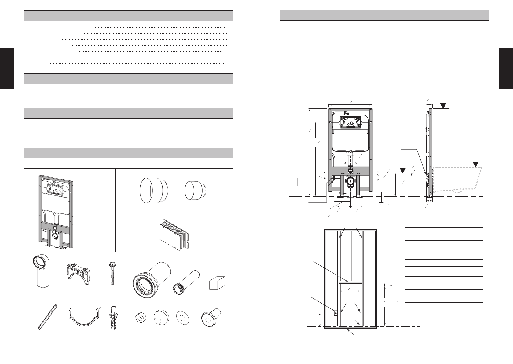
TABLE OF CONTENTS
!2
Thanks for Choosing TOTO
Common Tools Needed
Included Parts
Before Installation
ENGLISH
Installation Procedure
Servicing Procedures
Warranty
2
2
3
4-7
8-9
10
■
Read these instructions thoroughly before beginning work.
■
Please leave these instructions with the customer. They contain important mainte-
nance and warranty information.
■
If necessary, remove the existing toilet.
■
CAUTION! Be sure to properly bleed all air from the piping system prior to using
any TOTO products. Trapped/compressed air can cause damage to the fl ushing
BEFORE INSTALLATION
system and toilet bowl.
THANKS FOR CHOOSING TOTO!
The mission of TOTO is to provide the world with healthy, hygienic and more
comfortable lifestyles. We design every product with the balance of form and function
as a guiding principle. Congratulations on your choice.
Prepare the support for the carrier as shown. Consult with a building contractor and/or
local codes for any additional requirements. Add a double wall studs (king and jack)
and double header per the shown dimensions. Confirm that the opening is square.
1
(89)
inch
(mm)
13
22- "
(
)
580
16
3- "
H
2
ENGLISH
COMMON TOOLS NEEDED
• Hacksaw
• Flat File
• Drill
• 1/8” (3mm) Drill Bit
INCLUDED PARTS
Check to make sure you have all these parts from the package:
In Wall Tank
(Carrier)
Parts in Bag 1 Parts in Bag 2
Outlet Pipe Upper bracket
Threaded
Mounting Stud (2)
Lower
Bracket
Lag Screw
Anchor
• 3-1/2” (89mm) Hole Saw
• 7/16” (11mm) Open or Boxed-end Wrench
• Tape Measure
• Carpenter’s Level
Parts in Bag
(8)
(2)
Outlet Pipe
Mud Guard
Flange Pipe Inlet Pipe
Nut
(2)
Cap
(2)
Inlet Pipe
Mud Guard
Washer
(2)
Stud bolt Flange
Push Plate
Rough In
Lubricated
sponge
(2)
7
16
46- "
(
1180
(13)
½"
NPT
Water
Supply
NPT
½"
Optional
washlet
Connection
Header
(Double)
Optional
GFCL
Electrical
Outlet
)
39- "
(
1000
12"
(13)
½"
3
8
)
1
16
7- "
(
)
180
)
48
(
8
7
1- "
1- "
15
3- "
(
100
NPT
Water
Supply
R
D
7
(22)
8
3
(35)
8
16
)
12- "
"
5
8
(
)
320
Finished Floor
5
5
8- "
6- "
(
218
8
7
(
)
175
8
6- "
)
King Studs
5
8
16
"
3
(
157
16
-"
(
)
15-135
)
inch
3- "
Toilet Rim
Height (R)
15"
16"
17"
18"
19"
3
(86)
8
Height (H)
System
31"
32"
33"
34"
35"
Threaded Mounting
Stud Height (D)
11-29/64"
12-7/16"
13-15/32"
14-29/64"
15-1/2"
mm
7
(
8
22- "
580
Trimmer
(Jack)Studs
Sole Plate
Toilet Rim
Height (R)
(51)
45- "
(
1150-1280
3
8
2"
- 50- "
)
381
406
432
3
457
8
)
483
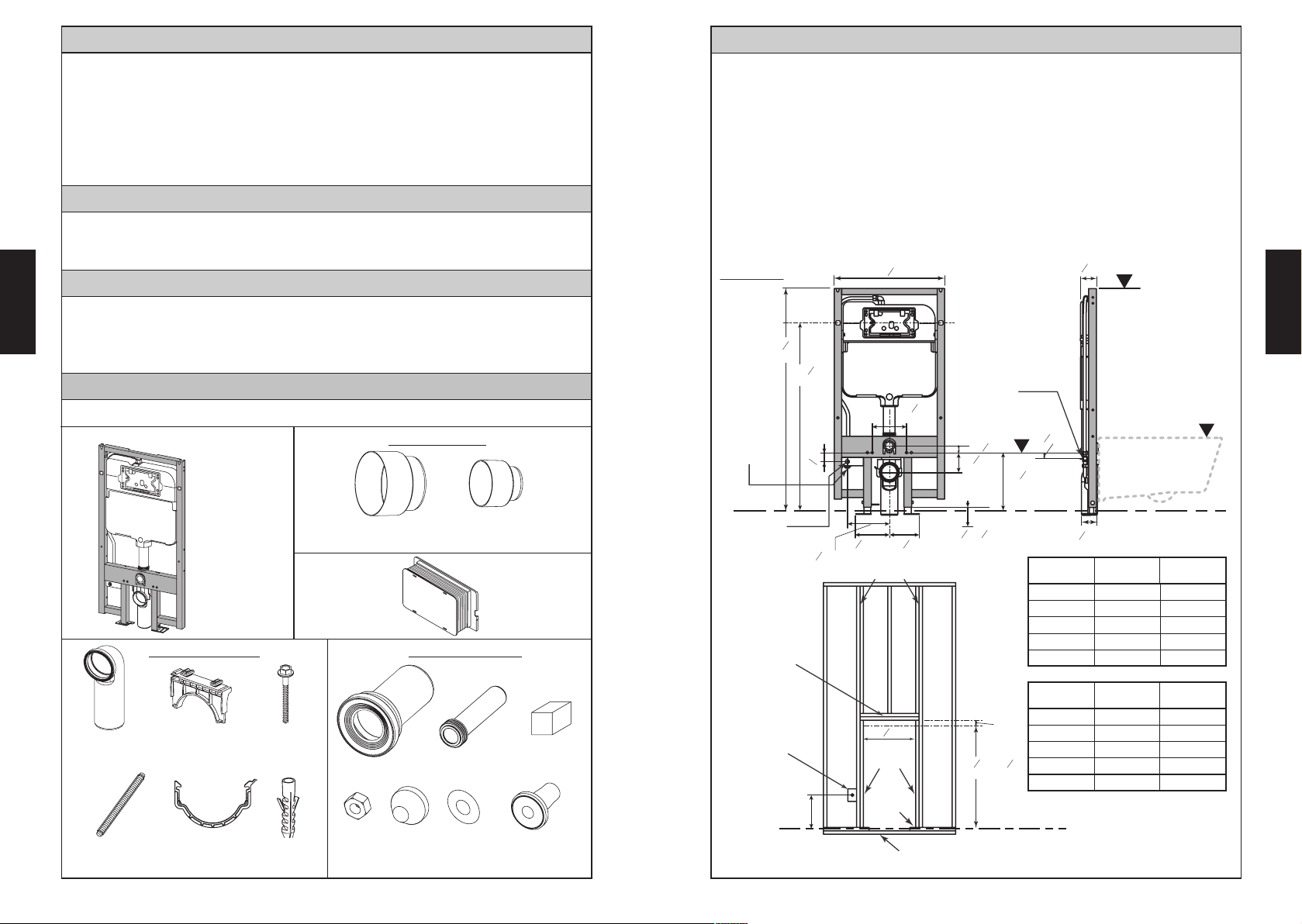
Ta ble 1:
Finished Floor
System
Height (H)
787
813
835
864
889
Threaded Mounting
Stud Height (D)
291
316
342
367
393
Dimensions measured from
Finished Floor
Sub-Floor
(plywood or concrete)
2
3
Page 3
INSTALLATION PROCEDURE
Installing the In-Wall Ta nk System
Use the lower bracket to lock the outlet pipe to the Carrier.
Place the carrier into the wood frame, make sure the carrier is horizontally leveled
and fl ush is placed in the front face of the stud frame.
Use the screws provided for securing the System. Install the outlet pipe to the
Loosen the bolts on the adjustable
legs and place the carrier into the
ENGLISH
wood frame.
Adjust the carrier to the desired
height with reference to the
Finished Floor (see Table 1 for
51
H
50
49
48
47
46
45
44
43
42
41
guide) and marked on the wood
frame.
Tighten the two bolts on the legs
sewer pipe.
H
1
1
ENGLISH
1
1
to secure the height of the carrier.
2
2
Mark the location for drilling pilot
holes for the screws to secure
the carrier to the wood frame.
There are six (6) screws for the
side (3 on each side) and two on
A
the feet. Make sure the carrier
is flush with the wood frame
before placing the markings.
Remove the carrier from the
wood frame, drill six (6) 1/8”(3mm)
A
A
holes on the wall stud (Trimmer/
Jack) and two (2) on the subfloor
(plywood); for concrete, drill 3/8”
(10mm) holes for anchors.
For vertical drain installation, clip the upper
bracket to the front slot of the frame as shown.
Drill a 3-3/4"(95mm) hole on the subfloor 1-3/4"
(45mm) from the front of studs.
(45)
1-¾"
Front Slot Back Slot
A
1
A
A
B
B
A
Ø 1/8" [3mm]
2
B
2
Ø 1/8"
1
[3mm]
leak. Do not remove the block cap of the
inlet for Washlet.
CAUTION
This indicates that misoperation could
result in injury or physical damage.
Plumb the water supply line and check for
For left or right drain installation, clip the upper bracket to
the back slot of the frame as
shown.
Required
It is important to reconfirm
that there is no water
leakage at all connections.
Incomplete connection
Before connecting the flexible hose
to the fill valve, open shutoff valve
to let water run for a minute or two.
After that, shut off the valve and the
main supply valve.
could cause foul odor or
water to leak.
The symbol indicates something that
must be done.
45°
45°
Insert the mud guard for the inlet and outlet, the push plate
rough-in for the push plate and the two (2) Threaded
Mounting Stud for the mounting bowl on the inner holes.
4
5
Page 4
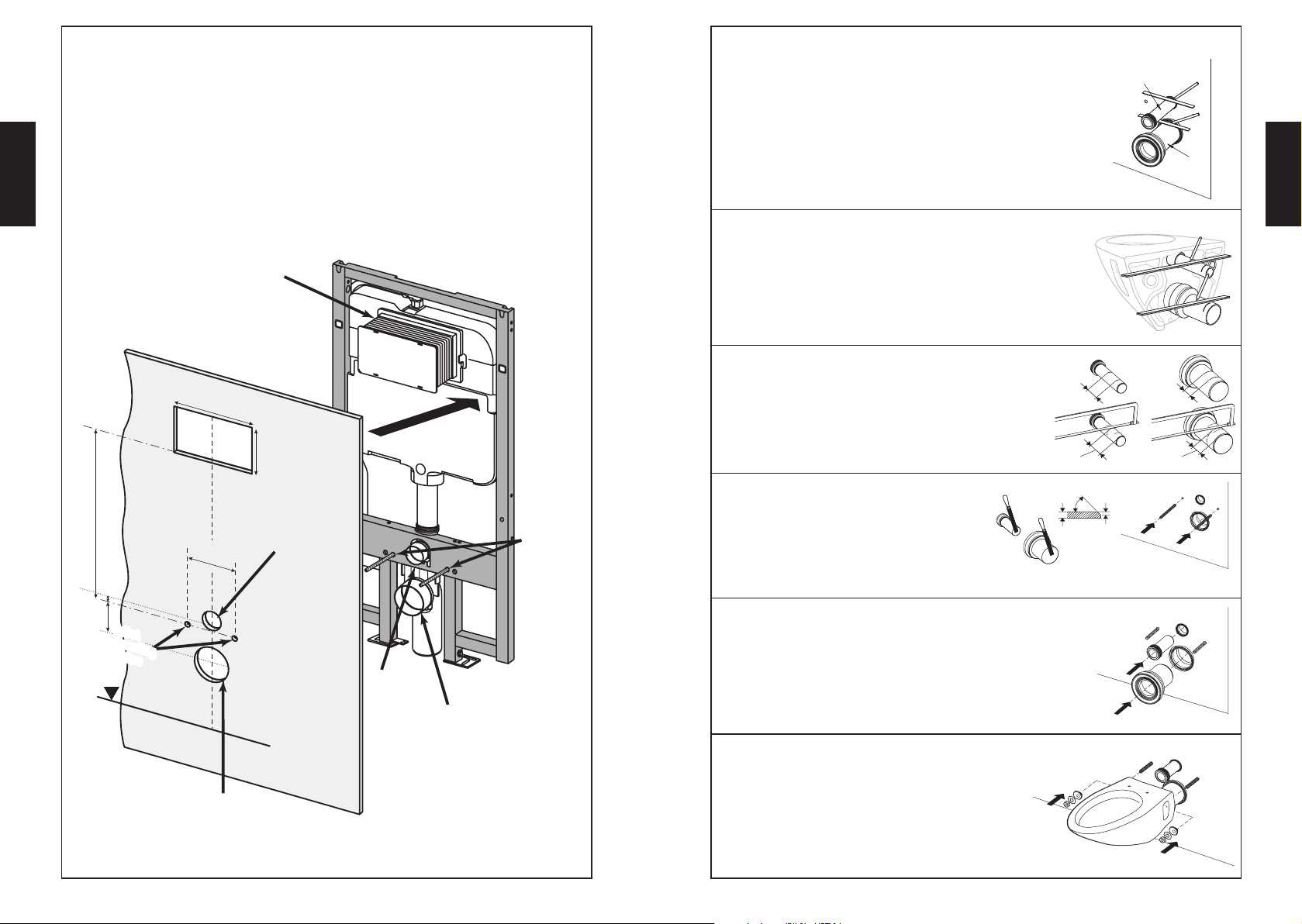
Cutting Out the Wall Location
Installing Toilet on the In-Wall Ta nk System
Recommended minimum 1/2” (13mm) drywall installation. Use the protruding
parts on the carrier to locate the cuts on the wall.
Cut a 4-1/2” (114mm) diameter hole for the outlet drain.
ENGLISH
Cut a 2-1/2” (64mm) diameter hole for the water inlet.
Cut two 3/4” (19mm) diameter holes for the threaded mounting stud.
Cut a 8-7/8” (226mm) x 5-9/16” (140mm) hole for the push plate.
Push Plate
Rough-In
Wall Panel (min.1/2
”
(13mm))
”
(226mm)
5-9/16
”
(140mm)
Inlet Drain Hole
Diameter
2-1/2”(D.64mm)
24” (610mm)
1-3/8”
(35mm)
Push Plate
8-7/8
7-1/6”(180mm)
Threaded
Mounting
Stud
Apply lubrication using the supplied sponge in the inlet and
1)
outlet drain to facilitate installation. Insert the inlet pipe into
the tank drain outlet until it stops.
Place the edge of a ruler against the fi nished wall and
on top of the inlet pipe. Mark the location as shown and
remove the inlet pipe.
Repeat this process with the fl ange pipe.
2) Insert the inlet pipe end with the gasket into the back of the
toilet bowl.
Place the edge of a ruler against the whole width of the back
of the toilet and on top of the inlet pipe. Mark the location as
shown and remove the inlet pipe.
Repeat this process with the flange pipe.
As shown in the figure, measure the distance between
3)
two lines "a" and "b". From that dimension, mark the
cutting line by measuring from the edge opposite from
the gasket and saw off the excess.
Repeat this process for the flange pipe.
a + 1/4”(3mm)
4) Bevel the cutting edges as shown.
Screw the threaded mounting studs onto
45˚
c
the tank and leave 2-1/8"(54mm) exposed.
Inlet Pipe
Flange
Pipe
ENGLISH
a
b + 1/4”(3mm)
1/2 c
b
Toilet
Mounting
Holes
F.L
3-15/16” (100mm)
Outlet Drain Hole
Diameter 4-1/2”(D.114mm)
6
Inlet Drain
mud guard
Outlet Drain
Mud Guard
5) Insert the inlet pipe and the flange pipe into the
appropriate drain holes.
6)
Install the toilet bowl by aligning it with the pipes
and threaded mounting stud. Use the included
mounting hardware to secure the bowl.
7
Page 5

SERVICING PROCEDURES
SERVICING PROCEDURES
Replacing the Flush Valve
1) Remove the splash guard and pull it
out.
5) Remove the hold-down bracket by
pulling on the tab indicated.
ENGLISH
1) Follow the procedure for removing the flush valve.
2) Disconnect the flexible hose from the fill valve.
3) Pull the hook toward you, slide the main unit up, and then remove the fill valve
main unit.
Adjusting the Water Level in the Ta nk
4) Turning the screw clockwise will raise the water level.
5) Turning the screw counterclockwise will lower the water level.
6) The water level must be 35mm [1-3/8"] for 1.28gpf/0.9gpf (4.8Lpf/3.4Lpf) and
ENGLISH
12mm [15/32"] for 1.6gpf/0.9gpf (6.0Lpf/3.4Lpf) below the overflow tube.
2) Close the shutoff valve in the tank,
and then push the button on the
actuator to flush the water.
3) Push on the tab to remove the actuator.
6) Pull the flush valve up, and rotate the
rods.
❷
❶
7) Rotate the whole unit as you pull it
out.
❷
❶
7) To install, follow the procedure
in reverse to return the fill valve to
its original position.
Flexible
hose
Water Level
Overflow pipe
Screw
35mm [1-3/8"] (1.28gpf/0.9gpf)
12mm [15/32"] (1.6gpf/0.9gpf)
4) Tilt the two pull-up rods of the flush
valve to the right.
❸
8) At the other end of the flush valve,
the rubber piece can be removed for
cleaning or to be replaced.
9) To install the parts back into the
tank, do the reverse order.
8
Fill Valve
Cleaning the Filter of the Fill Valve
1) Close the water shutoff valve, and then remove
the fill valve as described above.
As shown in the figure, disassemble the fill
2)
valve, and then either clean the filter with water
or use a brush to clean any dirt from it.
3)
To install, follow the procedure in reverse to
return the fill valve to its original position.
9
Page 6
WARRANTY
1.
TOTO warrants its In Wall Tank System (“Product”) to be free from defects in materials and
workmanship during normal use when properly installed and serviced, for a period of one (1)
year from date of purchase. This limited warranty is extended only to the ORIGINAL PURCHASER of the Product and is not transferable to any third party, including but not limited to
any subsequent purchaser or owner of the Product. This warranty applies only to TOTO Product
ENGLISH
purchased and installed in North, Central and South America.
2.
TOTO’s obligations under this warranty are limited to repair, replacement or other appropriate adjustment, at TOTO’s option, of the Product or parts found to be defective in normal
use, provided that such Product was properly installed, used and serviced in accordance with
instructions. TOTO reserves the right to make such inspections as may be necessary in order to
determine the cause of the defect. TOTO will not charge for labor or parts in connection with
warranty repairs or replacements. TOTO is not responsible for the cost of removal, return and/
or reinstallation of the Product.
This warranty does not apply to the following items:
3.
a.
b.
c. Damage or loss resulting from sediments or foreign matter contained in a water system.
d.
e.
f.
g. Tank fl ushing mechanisms of plastic or rubber moving parts.
h. Toilet seats of plastic, wood or metal.
4.
5.
6.
WARNING! TOTO shall not be responsible or liable for any failure of, or damage to, this Product caused by either chloramines in the treatment of public water supply or cleaners containing
chlorine (calcium hypochlorite). NOTE: The use of a high concentrate chlorine or chlorine related
products can seriously damage the fittings. This damage can cause leakage and serious property
damage.
THIS WRITTEN WARRANTY IS THE ONLY WARRANTY MADE BY TOTO. REPAIR, REPLACEMENT
OR OTHER APPROPRIATE ADJUSTMENT AS PROVIDED UNDER THIS WARRANTY SHALL BE
THE EXCLUSIVE REMEDY AVAILABLE TO THE ORIGINAL PURCHASER. TOTO SHALL NOT BE
RESPONSIBLE FOR LOSS OF THE PRODUCT OR FOR OTHER INCIDENTAL, SPECIAL OR CONSEQUENTIAL DAMAGES OR EXPENSES INCURRED BY THE ORIGINAL PURCHASER, OR FOR
LABOR OR OTHER COSTS DUE TO INSTALLATION OR REMOVAL, OR COSTS OF REPAIRS BY
OTHERS, OR FOR ANY OTHER EXPENSE NOT SPECIFICALLY STATED ABOVE. IN NO EVENT
WILL TOTO’S RESPONSIBILITY EXCEED THE PURCHASE PRICE OF THE PRODUCT. EXCEPT TO
THE EXTENT PROHIBITED BY APPLICABLE LAW, ANY IMPLIED WARRANTIES, INCLUDING THAT
OF MERCHANTABILITY OR
LY DISCLAIMED. SOME STATES DO NOT ALLOW LIMITATIONS ON HOW LONG AN IMPLIED
WARRANTY LASTS, OR THE EXCLUSION OR LIMITATION OF INCIDENTAL OR CONSEQUENTIAL DAMAGES, SO THE ABOVE LIMITATION AND EXCLUSION MAY NOT APPLY TO YOU.
Damage or loss sustained in a natural calamity such as fi re, earthquake, fl ood, thunder,
electrical storm, etc.
Damage or loss resulting from any accident, unreasonable use, misuse, abuse, negligence, or improper care, cleaning, or maintenance of the Product.
Damage or loss resulting from improper installation or from installation of the Product in
a harsh and/or hazardous environment, or improper removal, repair or modification of the
Product. (NOTE: Product model codes allow a maximum of 80 PSI. Check local codes or
standards for requirements).
Damage or loss resulting from electrical surges or lightning strikes or other acts which are
not the fault of TOTO or which the Product is not specified to tolerate.
Damage or loss resulting from normal and customary wear and tear, such as gloss reduction, scratching or fading over time due to use, cleaning practices or water or atmospheric
conditions.
In order for this limited warranty to be valid, proof of purchase is required. TOTO encourages
warranty registration upon purchase to create a record of Product ownership at http://www.
totousa.com. Product registration is completely voluntary and failure to register will not diminish your limited warranty rights.
THIS WARRANTY GIVES YOU SPECIFIC LEGAL RIGHTS. YOU MAY HAVE OTHER RIGHTS
WHICH VARY FROM STATE TO STATE, PROVINCE TO PROVINCE OR COUNTRY TO COUNTRY.
To obtain warranty repair service under this warranty, you must take the Product or deliver it
prepaid to a TOTO service facility together with proof of purchase (original sales receipt) and a
letter stating the problem, or contact a TOTO distributor or products service contractor, or write
directly to TOTO U.S.A., INC., 1155 Southern Road, Morrow, GA 30260 (678) 466-1300 or (888)
295 8134, if outside the U.S.A. If, because of the size of the Product or nature of the defect, the
Product cannot be returned to TOTO, receipt by TOTO of written notice of the defect together
with proof of purchase (original sales receipt) shall constitute delivery. In such case, TOTO may
choose to repair the Product at the purchaser’s location or pay to transport the Product to a
service facility.
FITNESS FOR USE OR FOR A PARTICULAR PURPOSE, ARE EXPRESS-
ENGLISH
10
11
Page 7
ÍNDICE
¡Gracias Por Elegir TOTO! ..........................................................................................12
Herramientas Necesarias .............................................................................................12
Partes Incluidas ...........................................................................................................12
Antes de la Instalación .................................................................................................13
Procedimiento de Instalación ..................................................................................14-17
Procedimiento de Servicio ......................................................................................18-19
Garantía ...................................................................................................................... 20
■
Lea estas instrucciones con cuidado antes de empezar a trabajar.
■
Deje este manual de instalación con el cliente, contiene importante información
de mantenimiento y garantía.
■
Si es necesario, retire el inodoro existente.
■
¡CUIDADO! Asegúrese de sacar adecuadamente todo el aire del sistema de
tubería antes de usar cualquier producto TOTO. El aire atrapado/comprimido
ANTES DE LA INSTALACIÓN
puede dañar el sistema de descarga y la taza del inodoro.
¡GRACIAS POR ELEGIR TOTO!
La misión de TOTO es dar al mundo estilos de vida más saludables, higiénicos y
cómodos. Diseñamos cada producto guiándonos por el principio del equilibrio entre
ESPAÑOL
forma y función. Felicitaciones por su elección.
Prepare el apoyo para el soporte como se muestra. Para cualquier requisito adicional, consulte con un contratista de construcción y/o códigos locales.
Añada pernos dobles de pared (principal y de gato) y un perno de cabezal doble
según las dimensiones indicadas. Confirme que la abertura es cuadrada.
1
(89)
pulgada
(mm)
13
22- "
(
)
580
16
3- "
H
2
HERRAMIENTAS NECESARIAS
• Sierra de Arco
• Archivo Plano
• Taladro
• 1/8” (3mm) Taladro Broca
• Sierra Perforadora 3-1/2” (89mm)
• Llave de estrella o de boca fija de 7/16" (11 mm)
• Cinta Métrica
• Nivel del Carpintero
PARTES INCLUIDAS
Asegúrese que todas estas partes estén incluidas en su empacado:
Partes en la Bolsa
Tanque
Empotrado
Partes en la Bolsa 1Partes en la Bolsa 2
Tubo de Salida Soporte superior
Perno de montaje
roscado (2)
Soporte
Inferior
Tornillo
(8)
Anclaje
(2)
Guardabarros de
tubería de salida
Tubo con Brida
Tuerca
(2)
12
Tapón
(2)
Guardabarros de
tubería de entrada
Tubo de
Entrada
Arandela
Placa de
(2)
perno prisionero (2)
Empuje
Esponja
lubricada
Brida de
7
46- "
(
1180
(13)
½"
Suministro
de agua
de NPT
Conexión
para Washlet
NPT de ½"
opcional
Cabezero
(Doble)
Toma de
corriente
eléctrica
GFCL
opcional
16
)
39- "
12"
3
8
(
)
1000
1
16
7- "
(
)
180
)
48
(
8
7
1- "
5
8- "
7
6- "
(
)
218
8
3
(
)
(
6- "
)
157
16
175
8
Tabla maestra
7
(
)
8
22- "
580
Pie
Derecha
Solera
Inferior
Bajo-Piso
(madera contrachapada o cemento)
1- "
15
3- "
(
100
5
8
"
(
15-135
45- "
(
1150-1280
13
3
8
16
)
5
16
-"
3
8
- 50- "
(13)
½"
Suministro
de agua
de NPT
D
7
8
(35)
12- "
"
5
8
(
)
320
Piso Terminado
)
pulgada
Altura de la taza
del inodoro (R)
15"
16"
17"
18"
19"
mm
Altura de la taza
del inodoro (R)
(51)
2"
381
406
432
3
8
457
)
483
Tabla 1:
Piso Terminado
(22)
3
(86)
8
3- "
Altura del
sistema (H)
Altura del
sistema (H)
montaje roscado (D)
31"
32"
33"
34"
35"
montaje roscado (D)
787
813
835
864
889
Altura del perno de
11-29/64"
12-7/16"
13-15/32"
14-29/64"
15-1/2"
Altura del perno de
291
316
342
367
393
Dimensiones medidas desde
el suelo terminado
ESPAÑOL
R
Page 8

PROCEDIMIENTO DE INSTALACIÓN
Instale el Sistema de Tanque Empotrado
Suelte los tornillos en las
51
patas ajustables y coloque el
ensamblado del tanque en el
marco.
Ajuste el tanque a la altura altura
con referencia al piso terminado.
(vea tabla 1 para guia) y marcado
en el marco de madera.
ESPAÑOL
Apriete los dos (2) tornillos a las
patas para asegurar la altura del
ensamblado del tanque.
H
50
49
48
47
46
45
44
43
42
41
Use el soporte inferior para encajar el tubo de salida al ensamblado del tanque.
Coloque el ensamblado del tanque en el marco de madera, asegurese que el
tanque esté nivelado horizontalmente y la descarga esté hacia afuera. Use los
tornillos provistos para fijar el Sistema. Instale el tubo de salida a la tubería de la
alcantarilla.
H
1
1
1
1
2
Marque la locación de taladrar agujeros
para los tornillos para sujetar el ensamblado del tanque al marco de madera.
Hay seís (6) tornillos para los lados (3 en
cada lado) y dos (2) para las patas.
A
A
Asegurese que el ensamblado del tanque
esté alineado con el marco de madera
antes de marcar.
Remueva el ensamblado del tanque del
marco de madera. Taladre seís (6)
A
A
A
A
agujeros de 1/8”(3mm) en la pie derecha
y dos (2) sobre el bajo-piso (madera
contrachapada). Para cemento, taladre
agujeros de 3/8”(10mm) para anclajes.
B
Para realizar la instalación de drenaje vertical,
enganche el soporte superior a la ranura frontal de
la estructura tal como se muestra. Realice un
orificio de 3-3/4” (95 mm) en el subsuelo, a 1-3/4”
(45 mm) desde la parte delantera de los pernos.
A
Ø 1/8" [3mm]
1
2
B
2
Ø 1/8"
1
B
[3mm]
Para realizar la instalación de drenaje
hacia la izquierda o hacia la derecha,
enganche el soporte superior a la
ranura trasera de la estructura tal
como se muestra.
Accione la línea de suministro de agua y
compruebe si hay fugas. No retirar el tapón
del bloque de la entrada de la cisterna.
PRECAUCIÓN
Esto señala que una mala operación
podría ocasionar una lesión o daño físico.
Es importante reconfirmar
que no hay fugas de agua
en todas las conexiones.
Obligatorio
Una conexión errónea
puede dar como resultado
malos olor o fuga de agua.
El símbolo señala algo que se debe
llevar a cabo.
2
ESPAÑOL
Antes de conectar la manguera flexible a la
válvula de llenado, abra la válvula de cierre y
deje correr el agua durante un minuto o dos.
Después de eso, cierre la válvula en el
tanque y la válvula de suministro principal.
1-¾"
(45)
Ranura frontal Ranura trasera
14
45°
45°
Introduzca el guardabarros para la entrada y la salida,
la placa de empuje rugosa para la placa de empuje y
los dos (2) pernos de montaje roscados para el montaje de la taza en los orificios interiores.
15
Page 9

Cortando la Ubicación de la Pared
Instalación del Inodoro al Sistema de Tanque Empotrado
Las instrucciones recomiendan para la instalación de pared de yeso de 1/2” (13 mm).
Utilice las partes salientes en el ensamblado del tanque para ubicar los cortes en la pared.
1)
Aplique lubricación con la esponja suministrada en el drenaje de
entrada y salida para facilitar la instalación. Introduzca la tubería de
Tubo de Entrada
entrada en la salida del drenaje del depósito hasta que se detenga.
Corte un orificio de 4-1/2” (114mm) de diámetro para el drenaje de salida.
Corte un orificio de 2-1/2” (64mm) de diámetro para la entrada de agua.
Practique dos agujeros de 3/4” (19 mm) de diámetro para el perno de montaje roscado.
Corte un orificio de 8-7/8" (226 mm) x 5-9/16" (140 mm) para la placa de empuje rugosa.
Coloque la orilla de una regla contra la pared terminada y
arriba del tubo de entrada. Marque la ubicación como se
muestra y retire el tubo de entrada.
Repita este proceso con el tubo con brida.
2) Inserte el extremo del tubo de entrada con la junta en la parte
Tubo con
Brida
de atrás de la taza del inodoro.
ESPAÑOL
Placa de empuje rugosa
Coloque la orilla de una regla contra todo el ancho de la parte
posterior del inodoro y arriba del tubo del tubo de entrada.
Marque la ubicación como se muestra y retire el tubo de entrada.
Panel de pared (mín. 1/2" (13 mm))
Placa de empuje de 8-7/8"
(226 mm)
Repita este proceso con el tubo con brida.
Como se muestra en la ilustración, mida la distancia entre
3)
las líneas "a" y "b". A partir de esa dimensión, marque la
línea de corte midiendo desde el borde opuesto a
a
b
ESPAÑOL
la junta y corte el exceso.
Repita este proceso para la brida.
4) Haga un bisel a las orillas cortadas como
se muestra.
Atornille los pernos de montaje roscados en
el tanque y deje 2-1 / 8 "(54mm) expuestos.
a + 1/4”(3mm)
c
b + 1/4”(3mm)
45˚
1/2 c
24” (610mm)
1-3/8”
(35mm)
7-1/6”(180mm)
5-9/16
”
(140mm)
Orificio de drenaje de
entrada Diámetro
2-1/2" (D.64 mm)
Perno de
montaje
roscado
Montaje
del inodoro
Orificios
F.L
3-15/16” (100mm)
Diámetro del orificio de
la salida del desagüe 4-1/2"
(D.114 mm)
16
Guardabarros
de drenaje
de entrada
Guardabarros
de drenaje
de salida
5) Inserte el tubo de entrada y el tubo con
brida a los orificios de drenaje adecuados.
6)
Instale la taza del inodoro alineándola con las
tuberías y el perno de montaje roscado. Fije la
taza con las herramientas de montaje que se
incluyen.
17
Page 10

PROCEDIMIENTO DE SERVICIO
PROCEDIMIENTO DE SERVICIO
Sustitución de la válvula de descarga
1) Remove the splash guard and pull it
out.
5) Remove the hold-down bracket by
pulling on the tab indicated.
1) Siga el siguiente procedimiento para extraer la válvula de descarga.
2) Desconecte la manguera flexible de la válvula de llenado.
Ajustando el Nivel de Agua en el Tanque
3) Tire del enganche hacia usted, deslice la unidad principal hacia arriba y, a continuación, extraiga la unidad principal de la válvula de llenado.
4) Al girar el tornillo hacia la derecha, se eleva el nivel de agua.
5) Al girar el tornillo hacia la izquierda, disminuye el nivel de agua.
6) El nivel del agua debe ser 35 mm [1-3/8"] para 1,28 GPD/0,9 GPD (4,8 Lpd/3,4
Lpd) y 12 mm [15/32"] para 1,6 GPD/0,9 GPD (6,0 Lpd/3,4 Lpd) por debajo del
2) Close the shutoff valve in the tank,
ESPAÑOL
and then push the button on the
6) Tire de la válvula de descarga hacia
arriba y gire las varillas.
actuator to flush the water.
tubo de rebose.
Para realizar la instalación, siga el procedimiento
7)
en el orden inverso con el fin de que la válvula
de llenado regrese a su posición original.
3) Push on the tab to remove the actuator.
❷
❶
7) Gire toda la unidad a la vez que la
extrae.
❷
❶
Manguera
flexible
Nivel del
agua
Tornillo
35 mm [1-3/8"] (1,28 GPD/0,9 GPD)
12 mm [15/32"] (1,6 GPD/0,9 GPD)
ESPAÑOL
4) Incline las dos varillas de tracción de
la válvula de descarga hacia la derecha.
❸
8) En el otro extremo de la válvula de
descarga, la pieza de goma puede
extraerse para su limpieza o sustitución.
9) Para volver a montar las piezas en el
depósito, siga el orden inverso.
18
Tubo de rebose
Válvula de llenado
Limpiando el Filtro de la Válvula de Llenado
1) Cierre la válvula de cierre del agua y, a continuación, retire la válvula de llenado tal como
se describe anteriormente.
2) Ta l como se muestra en la ilustración, desmonte la válvula de llenado y, a continuación,
limpie el filtro con agua o utilice un cepillo
para limpiar cualquier suciedad del mismo.
3) Para realizar la instalación, siga el procedimiento en el orden inverso con el fin de que
la válvula de llenado regrese a su posición
original.
19
Page 11

GARANTÍA
®
1. TOTO
2.
3. Esta garantía no aplica a los siguientes puntos:
ESPAÑOL
a. Daño o pérdida ocurridos en un desastre natural, tal como un incendio, terremoto, inundación,
b. Daño o pérdida resultado de cualquier accidente, uso no razonable, mal uso, abuso, negligen-
c. Daño o pérdida resultado de sedimentos o materia extraña contenidos en un sistema de aguas.
d. Daño o pérdida resultado de una instalación inadecuada o de la instalación del Producto en
e. Daño o pérdida resultado de sobrecarga eléctrica o rayos u otros actos que no sean culpa de
f. Daño o pérdida resultado del desgaste normal y acostumbrado, tal como reducción del brillo,
g. Mecanismos de descarga del tanque de plástico o partes movibles de hule.
h. Asientos de inodoro de plástico, madera o metal.
4.
5.
6.
¡ADVERTENCIA! TOTO no será responsable de cualquier falla de, o daño a, este Producto causado por
cloraminas en el tratamiento del suministro de agua público o limpiadores que contengan cloro (hipoclorito de calcio). NOTA: El uso de un cloro de concentración alta o productos relacionados con cloro
puede dañar severamente los accesorios. Este daño puede causar fugas y un grave daño a la propiedad.
ESTA GARANTÍA ESCRITA ES LA ÚNICA GARANTÍA HECHA POR TOTO. LA REPARACIÓN, CAMBIO U
OTRO AJUSTE ADECUADO, SEGÚN LO ESTIPULADO EN ESTA GARANTÍA, SERÁ EL ÚNICO REMEDIO
DISPONIBLE PARA EL COMPRADOR ORIGINAL. TOTO NO SERÁ RESPONSABLE DE LA PÉRDIDA DEL
PRODUCTO O DE OTROS DAÑOS INCIDENTALES, ESPECIALES O CONSECUENCIALES O GASTOS
INCURRIDOS POR EL COMPRADOR ORIGINAL, O PARA EL TRABAJO U OTROS COSTOS DEBIDO A
LA INSTA LACIÓN O REMOCIÓN, O COSTOS DE REPARACIONES HECHAS POR TERCEROS, O POR
CUALQUIER OTRO GASTO NO DECLARADO ESPECÍFICAMENTE ARRIBA. EN NINGÚN CASO, LA
RESPONSABILIDAD DE TOTO EXCEDERÁ EL PRECIO DE COMPRA DEL PRODUCTO. EXCEPTO AL
GRADO PROHIBIDO POR LA LEY APLICABLE, CUALQUIER GARANTÍA IMPLÍCITA, INCLUYENDO LA
DE COMERCIABILIDAD O ADECUACIÓN PARA SU USO O PARA UN PROPÓSITO EN PA RTICULAR, SE
DECLARARÁ EXPRESAMENTE. ALGUNOS ESTADOS NO PERMITEN LAS LIMITACIONES EN LA DURACIÓN DE UNA GARANTÍA IMPLÍCITA, O LA EXCLUSIÓN O LIMITACIÓN DE LOS DAÑOS INCIDENTALES O CONSECUENCIALES, POR LO QUE LA LIMITACIÓN O INCLUSIÓN ANTERIORES PUEDE NO
APLICAR PARA USTED.
garantiza que su Sistema de Tanque Empotrado (“Producto”) no tiene defectos en los materiales y mano de obra durante su uso normal, cuando es adecuadamente instalado y cuidado, por un
periodo de un (1) año a partir de la fecha de compra. Esta garantía limitada se extiende únicamente
al COMPRADOR ORIGINAL del Producto y no es transferible a ninguna tercera persona, incluyendo,
pero sin limitarse a, cualquier comprador o dueño subsecuente del Producto. Esta garantía aplica únicamente al Producto TOTO adquirido e instalado en América del Norte, Central y del Sur.
Las obligaciones de TOTO bajo esta garantía se limitan a reparar, reemplazar u otro ajuste adecuado,
a elección de TOTO, del Producto o partes que estén defectuosas con el uso normal, dado que dicho
Producto haya sido adecuadamente instalado, utilizado y cuidado de acuerdo con las instrucciones.
TOTO se reserva el derecho de hacer dichas inspecciones, ya que pueden ser necesarias con el fi n de
determinar la causa del defecto. TOTO no cobrará por el trabajo o partes relacionados con las reparaciones o cambios de la garantía. TOTO no es responsable por el costo de remoción, devolución y/o
reinstalación del Producto.
truenos, tormenta eléctrica, etc.
cia o cuidado, limpieza o mantenimiento inadecuado del Producto.
un ambiente hostil y/o peligroso, o la remoción, reparación o modificación inadecuada del
Producto. (NOTA: Los códigos del modelo del producto permiten un máximo de 80 PSI. Revise
los códigos locales ó estándares para los requisitos).
TOTO o que el Producto no esté especifi cado para tolerar.
rayado u opacamiento en el tiempo debido al uso, prácticas de limpieza o agua o condiciones
atmosféricas.
Con el fi n de que esta garantía limitada sea válida, se requiere una prueba de compra. TOTO le aconseja el registro de la garantía al momento de la compra para crear un registro de la propiedad del
Producto en http://totousa.com. El registro del Producto es completamente voluntario y no hacerlo no
disminuirá los derechos de su garantía limitada.
ESTA GARANTÍA LE OTORGA DERECHOS LEGALES ESPECÍFICOS. USTED PUEDE TENER OTROS
DERECHOS QUE PUEDEN VARIAR ENTRE ESTADOS, PROVINCIAS O PA ÍSES.
Para obtener un servicio de reparación por garantía bajo esta garantía, debe llevar el Producto o envi-
prepagado a las instalaciones de servicio TOTO junto con su prueba de compra (recibo de venta
arlo
original) y una carta declarando el problema, o póngase en contacto con un distribuidor de TOTO o
contratista de servicio de productos, o escriba directamente a TOTO U.S.A., INC., 1155 Southern Road,
Morrow, GA 30260 (888) 295 8134 ó (678) 466-1300, si está fuera de los Estados Unidos. Si, debido al
tamaño del Producto o naturaleza del defecto, el Producto no puede devolverse a TOTO, la recepción
de TOTO del aviso por escrito del defecto junto con la prueba de compra (recibo de venta original)
constituirá el envío. En tal caso, TOTO puede elegir entre reparar el Producto en la ubicación del comprador o pagar el transporte del Producto a unas instalaciones de servicio.
ESPAÑOL
20
21
Page 12

Merci d’Avoir Choisi TOTO! .........................................................................................22
Outils Communs Nécessaires ......................................................................................22
Pièces Incluses .............................................................................................................22
Avant de Commencer ...................................................................................................23
Procédure d’Installation ...........................................................................................24-27
Procédure d ‘Entretien .............................................................................................28-29
Garantie .......................................................................................................................30
La mission de TOTO est d’offrir au monde entier un style de vie sain, hygiénique et
plus confortable. comme principe de base, nous concevons chaque produit avec un
équilibre entre la forme et la fonction. félicitations pour votre choix.
• Scie à Métaux
• Lime Plate
• Perceuse
• 1/8” (3mm) Foret
FRANÇAIS
Vérifi ez que toutes les pièces sont inclues dans votre paquet:
Tuyau de Sortie Cadre supérieur
Goujon de montage
fileté (2)
TABLE DES MATIÈRES
MERCI D’AVOIR CHOISI TOTO!
OUTILS COMMUNS NÉCESSAIRES
• Scie à 3-1/2” (89mm)
• Clé à cliquet ou clé plate 7/16" (11 mm)
• Mètre à Ruban
• Niveau du Charpentier
PIÈCES INCLUSES
Pièces dans le Sac
Réservoir
Mural
Pièces dans le Sac 1
Support
Inférieur
Tirefond
(8)
Boulon
d’ancrage (2)
Garde-boue de la
conduite d’évacuation
Tuyau à Bride
Écrou
Capuchon
(2)
Garde-boue de
la conduite d’arrivée
Dimension Brute de la
Plaque de Poussée
Pièces dans le Sac 2
Tuyau
d’Entrée
Rondelle
(2)
(2)
Éponge
lubrifiée
Bride de
boulon fileté (2)
AVANT DE COMMENCER
■
Lisez complètement ces instructions avant de commencer le travail.
■
Veuillez laisser ces instructions pour le client. Elles contiennent des information
importantes sur l’entretien et la garantie.
■
Si nécessaire, enlevez la toilette déjà présente.
■
ATTENTION! Assurez vous d’évacuer tout air présent dans le système de tuyauterie avant d’utiliser les produits TOTO. Tout air bloqué ou comprimé peut endommager le système d’évacuation et la cuvette de la toilette.
Préparer le support pour l’élément porteur comme illustré. Prendre contact avec une
société de construction et/ou consulter les codes en bâtiment applicables dans votre
région pour tout besoin supplémentaire.
Ajouter des poteaux muraux doubles et un poteau double avec les dimensions illustrées.
Vérifier que l’ouverture est carrée.
13
(
(mm)
pouces
46- "
(
1180
(13)
½"
Alimentation
en eau
NTP
Raccord
bidet ½" NPT
en option
Linteau
Prise
électrique
avec
différentiel
en option
7
16
)
39- "
12"
(
1000
3
8
7
8- "
)
)
48
(
8
1- "
7
6- "
5
(
)
218
8
Poteau renfort
(contreplaqué or ciment)
22- "
(
175
8
22- "
Poteau
Lisse
d’assise
580
16
7- "
(
180
3
)
6- "
7
(
8
580
Sous-sol
1
16
)
)
(13)
½"
Alimentation
en eau
NTP
16
)
3- "
(
100
3
1- "
15
16
)
D
(35)
8
5
8
12- "
(
)
320
Sol fini
5
5
8
16
"
(
157
-"
)
(
)
15-135
pouces
Hauteur du rebord
mm
Hauteur du rebord
(51)
2"
3
3
8
- 50- "
(
1150-1280
8
)
45- "
Tableau 1:
Sol fini
3- "
7
(22)
8
"
3- "
des toilettes (R)
15"
16"
17"
18"
19"
des toilettes (R)
381
406
432
457
483
1
(89)
H
2
3
(86)
8
Hauteur du
système (H)
Hauteur du
système (H)
Hauteur du goujon de
montage fileté (D)
31"
11-29/64"
32"
33"
34"
13-15/32"
14-29/64"
35"
Hauteur du goujon de
montage fileté (D)
787
813
835
864
889
12-7/16"
15-1/2"
291
316
342
367
393
dimensions mesurées
à partir du sol fini
R
FRANÇAIS
22
23
Page 13

PROCEDURE D’INSTALLATION
L’installation du Système de Réservoir Mural
Desserrez les boulons sur les pieds
réglables et placez le support
dans le cadre en bois.
Ajustez le support à la hauteur
souhaitée en se référant aux sol
fi ni (voir le tableau 1 pour le guide)
et marqué sur le cadre en bois.
Serrez les deux boulons sur les
jambes pour sécuriser la hauteur
de la porte.
Utilisez le support inférieur pour verrouiller le tuyau de sortie du système
Placez le support dans le cadre en bois, assurez-vous que le système est
horizontalement nivelé et chasse d’eau est placé dans la face avant du cadre.
Utiliser les vis fournies pour sécuriser le système. Installer le tuyau de sortie de la
51
H
50
49
48
47
46
45
44
43
42
41
canalisation d’égout.
H
1
1
1
1
2
2
Marquez l’emplacement pour percer
FRANÇAIS
des trous pilotes pour les vis pour
fixer le support au cadre en bois.
Il y a six (6) vis pour le côté (3 de
chaque côté) et deux sur les pieds.
A
A
Assurez-vous que le réservoir est au
ras du cadre en bois avant de placer
les marquages.
Retirez le support du cadre en bois,
percer les six (6) 1/8”(3mm) trous sur
A
A
A
A
le poteau mural (régleur/Jack) et deux
(2) sur le sous-sol (contreplaqué);
pour le ciment, percez 3 / 8”(10mm)
trous pour les ancres .
B
B
Pour une installation verticale de l’écoulement, clipser
le cadre supérieur dans la fente avant du cadre
comme illustré. Percer un trou de 3-3/4" (95 mm) sur
le sous-sol à 1-3/4" (45 mm) de l’avant des poteaux.
A
Ø 1/8" [3mm]
1
2
B
2
Ø 1/8"
1
[3mm]
Pour une installation à gauche ou
à droite de l’écoulement, clipser le
cadre supérieur dans la fente
arrière du cadre comme illustré.
Sonder la conduite d’alimentation en eau et
vérifier l’absence de fuites. Ne pas retirer le
capuchon de l'arrivée d'eau du bidet.
MISE EN GARDE
Ce symbole indique que toute utilisation incorrecte peut
entraîner des blessures ou des dommages matériels.
Il est important de confirmer
qu'il n'y a pas de fuite d'eau
à toutes les connexions.
Requis
Un mauvais raccordement peut
entraîner le dégagement d’odeur
Avant de connecter le tuyau flexible à la vanne
de remplissage, ouvrir la vanne d’eau pour
laisser l’eau s’écouler une ou deux minutes.
FRANÇAIS
Après cela, fermez la vanne dans le réservoir
et la vanne d'alimentation principale.
nauséabondes ou une fuite d'eau.
Le symbole indique que quelque
chose doit être fait.
45°
45°
Insérer le garde-boue pour l’ arrivée et l’ évacuation, la
découpe de la plaque de poussée pour la plaque de poussée et les deux (2) goujons de montage filetés pour la
1-¾"
(45)
Fente avant Fente arrière
cuvette de montage sur les trous intérieurs.
24
25
Page 14

Découpez l’Emplacement Murale
Les instructions sont recommandées pour les installations dans les cloisons sèches de
1/2” (13mm). Utilisez les parties saillantes sur le support pour localiser les coupures sur
le mur.
Coupez un trou d’un diamètre de 4-1/2” (114mm) pour le drain de sortie.
Coupez un trou d’un diamètre de 2-1/2” (64mm) pour l’entrée d’eau.
Découper deux trous de diamètre 3/4" (19 mm) pour le goujon de montage fileté.
Découper une ouverture de 8-7/8" (226 mm) x 5-9/16" (140 mm) pour la plaque de poussée.
Découpe de la
plaque de poussée
1)
Appliquer du lubrifiant à l’aide de l’éponge fournie dans l’arrivée et
l’évacuation de la canalisation pour faciliter l’installation. Insérer la conduite
d’arrivée dans l’évacuation de la canalisation du réservoir jusqu’à la butée.
Placez le bord d’une règle contre le mur fini et sur le dessus du
tuyau d’admission. Marquez l’emplacement comme indiqué et
retirez le tuyau d’admission.
Répétez la procédure avec le tuyau à bride.
2) Insérez l’extrémité du tuyau d’entrée avec le joint à l’arrière de
la cuvette des toilettes.
Placez le bord d’une règle sur toute la largeur de l’arrière
de la toilette et au-dessus du tuyau d’admission. Marquez
Installez la Toilette sur la Porteuse
Tuyau
d’entrée
Tuyau à
Bride
l’emplacement comme indiqué et retirez le tuyau d’admission.
Répétez la procédure avec le tuyau à bride.
Panneau mural (min.1/2"(13 mm))
3)
FRANÇAIS
Plaque de poussée 8-7/8"
(226 mm)
Comme illustré sur la figure, mesurer la distance entre les
deux lignes « a » et « b ». À partir de cette dimension,
marquer la ligne de coupe en mesurant le bord opposé du
a
b
joint et découper le surplus.
5-9/16
”
(140mm)
Répéter la procédure pour le tuyau de la bride.
a + 1/4”(3mm)
b + 1/4”(3mm)
FRANÇAIS
24” (610mm)
1-3/8”
(35mm)
Ouvertures de
montage des
toilettes
F.L
3-15/16” (100mm)
Ouverture de
l’arrivée de la
7-1/6”(180mm)
Ouverture de la sortie de la
canalisation 4-1/2"(D.114 mm)
canalisation Diamètre
2-1/2"(D.64 mm)
26
Garde-boue de
l’arrivée de
la canalisation
Garde-boue de
l’évacuation de
la canalisation
Goujon de
montage
fileté
4) Biseautez les arêtes de coupe, tel
qu’illustré.
Vissez les goujons de montage filetés sur le
réservoir et laissez exposer 2-1 / 8 "(54mm).
5) Insérez le tuyau d’entrée et le tuyau à
bride dans les drains appropriés.
6)
Installer la cuvette des toilettes en l’ alignant
avec les tuyaux et le goujon de montage fileté.
Utiliser les accessoires de montage fournis
pour fixer la cuvette.
27
45˚
c
1/2 c
Page 15

PROCÉDURE D ‘ENTRETIEN
PROCÉDURE D ‘ENTRETIEN
Remplacer la vanne de la chasse d’eau
1) Remove the splash guard and pull it
out.
5) Remove the hold-down bracket by
pulling on the tab indicated.
1) Suivre la procédure pour retirer le robinet de la chasse d’eau.
2) Déconnecter le flexible de la vanne de remplissage.
Ajustez le Niveau d’Eau dans le Réservoir
3) Tirer le crochet vers soi, faire glisser l'unité principale vers le haut, puis retirer
l'unité principale de la vanne de remplissage
4) Tourner la vis dans le sens horaire permet d'augmenter le niveau d'eau.
5) Tourner la vis dans le sens antihoraire permet de diminuer le niveau d'eau.
6) Pour 1,28 GPF/0,9 GPF (4,8 Lpf/3,4 Lpf), le niveau d'eau doit être de 35 mm
(1-3/8") et pour 1,6 GPF/0,9 GPF (6,0 Lpf/3,4 Lpf), il doit être de 12 mm (15/32")
2) Close the shutoff valve in the tank,
and then push the button on the
actuator to flush the water.
6) Soulever le robinet de la chasse
d’eau et tourner les tiges.
en-dessous du tuyau de trop-plein.
7) Pour l'installer, suivre la procédure inverse
pour remettre la vanne de remplissage
dans sa position originale.
❷
❶
FRANÇAIS
3) Push on the tab to remove the actuator.
7) Tourner l’ ensemble de l’ unité en la
sortant.
❷
❶
Flexible
Niveau
d’eau
Vis
FRANÇAIS
35 mm (1-3/8") (1,28 GPF/0,9 GPF)
12 mm (15/32") (1,6 GPF/0,9 GPF)
4) Incliner les deux tiges d’arrêt du robinet de la chasse d’eau vers la droite.
❸
8) À l’autre extrémité du robinet de la
chasse d’eau, la pièce en caoutchouc peut être retirée pour être
nettoyée ou remplacée.
9) Procéder dans l’ordre inverse pour
réinstaller les pièces sur le réservoir.
28
Tuyau de trop-plein
Vanne de remplissage
Nettoyez le Filtre de la Valve de Remplissage
1) Fermer la vanne d'eau, puis retirer la vanne
de remplissage comme décrit ci-dessus.
2) Comme illustré dans la figure, démonter la
vanne de remplissage, puis nettoyer le filtre
avec de l'eau ou utiliser une brosse pour nettoyer la poussière présente.
3) Pour l'installer, suivre la procédure dans le
sens inverse pour remettre la vanne de remplissage dans sa position originale.
29
Page 16

GARANTIE
1. TOTO® garantit que son Système de Réservoir Mural (“Produit”) est libre de tout défaut de matériel et
de fabrication lors de l’usage normal, quand le produit est installé et entretenu correctement, pour (1)
an à partir de la date d’achat. Cette garantie limitée s’étend seulement à l’ACHETEUR ORIGINAL du
produit et n’est pas transférable à une autre entité, inclus et non limitée à tout acheteur ou propriétaire
du produit. Cette garantie s’applique seulement aux produits TOTO achetés et installés en Amérique
du Nord, Centrale et du Sud.
Les obligations de TOTO sous cette garantie sont limitées à la réparation, au remplacement et autre
2.
ajustement jugés approprié, au choix de TOTO, du Produit ou des pièces jugées défectives lors de
l’usage normal, pourvu qu’un tel Produit ait été installé correctement, utilisé et entretenu selon les
instructions. TOTO se réserve le droit de faire les inspections qui peuvent être nécessaires afin de
déterminer la cause du défaut. TOTO ne facturera pas de main-d’œuvre ou les pièces relatives aux
réparations ou aux remplacements sous garantie. TOTO n’est pas responsable pour le coût du retrait,
les frais de retour et/ou la réinstallation du produit.
3.
Cette garantie ne s’applique pas aux éléments suivants:
a.
b.
c.
d.
e.
FRANÇAIS
f.
g.
h.
4.
5.
6.
ATTENTION! TOTO ne peut être tenu responsable de toute défaillance, ou de dommages, causés à ce
produit par des chloramines dans le traitement de l’approvisionnement public en eau ou de nettoyants
contenant du chlore (hypochlorite de calcium). REMARQUE: L’ utilisation de chlore à forte concentration
ou de produits dérivés du chlore peut sérieusement endommager les raccords. Ces dommages peuvent
entraîner des fuites et des dommages matériels graves.
CETTE GARANTIE ÉCRITE CONSTITUE LA SEULE GARANTIE DE TOTO. TOUTE REPARATION, REMPLACEMENT OU AUTRE AJUSTEMENT EN CONSÉQUENT COUVERTS PAR CETTE GARANTIE SERA
LE SEUL RECOURS DISPONIBLE A L’ ACHETEUR ORIGINAL.TOTO NE SERA PA S RESPONSIBLE DE LA
PERTE DU PRODUIT OU POUR D’AUTRES DOMMAGES ACCESSOIRES, SPECIAUX OU INDIRECTES,
OU DE DEPENSES ENGAGÉES PAR L’ACHETEUR INITIAL, OU POUR LA MAIN D’OEUVRE OU D’AUTRES
COUTS DUS A L’ INSTALLATION OU LE RETRAIT, OU AU FRAIS
POUR TOUTES AUTRES CHARGES NON SPECIALEMENT INDIQUÉES CI-DESSUS. EN AUCUN CAS LA
RESPONSABILITE DE TOTO DEPASSERA-T-ELLE LE PRIX D’ACHAT DU PRODUIT. SAUF DANS LES LIMITES AUTORISÉES PAR LA LOI APPLICABLE, TOUTE GARANTIE IMPLICITE Y COMPRISES LES GARANTIES DE QUALITÉ MARCHANDE ET/OU L’UTILISATION À DES FINS EN PARTICULIER SONT EXPRESSEMENT EXCLUES. CERTAINS ÉTATS N’AUTHORISENT PAS LES LIMITATIONS SUR LA DURÉE D’UNE
GARANTIE IMPLICITE, OU L’EXCLUSION OU LA LIMITATION DES DOMMAGES INCIDENTS OU INDIRECTS, DONC LA LIMITATION ET L’EXCLUSION CI-DESSUS POURRAIT NE PAS S’APPLIQUER A VOUS.
Dommage ou perte causé par une calamité naturelle telle qu’un incendie, un tremblement de
terre, une inondation, la foudre, un orage, etc.
Dommage ou perte résultant d’un accident, un usage abusif, l’abus, de la négligence ou de
mauvais soins, de nettoyage ou de maintenance du produit.
Dommage ou perte résultant de sédiments ou de matières étrangères contenues dans un système d’eau.
Dommage ou perte résultant d’une mauvaise installation ou de l’installation du Produit dans
un environnement rude et / ou un environnement dangereux, ou une mauvaise désinstallation,
réparation ou modification du produit. NOTE: Les codes des modèles de ces produits permettent un maximum de 80 PSI.
Dommage ou perte résultant de surtensions ou la foudre ou d’autres actes qui ne sont pas la
faute de TOTO ou que le produit n’est pas spécifié à tolérer.
Dommage ou perte résultant de l’usure normal et habituel, telles que la réduction du lustre,
le grattage ou la décoloration au fil du temps due à l’utilisation, les pratiques de nettoyage ou
l’eau ou les conditions atmosphériques.
Mécanismes de chasse d’eau du réservoir en plastique ou des pièces en caoutchouc qui bougent.
Les sièges des toilettes en plastique, en bois ou en métal.
Pour que cette garantie limitée soit valide, une preuve d’achat est nécessaire. TOTO vous encourage à enregistrer la garantie à l’achat pour créer un enregistrement de la propriété du produit sur le
site http://www.totousa.com. L’ enregistrement du produit est complètement volontaire et le défaut
d’enregistrement ne diminuera en rien vos droits de garantie limitée.
CETTE GARANTIE VOUS DONNE DES DROITS LÉGAUX SPÉCIFIQUES. VOS DROITS POURRAIENT
VARIER D’UN ÉTAT A UN AUTRE, D’UNE PROVINCE A UNE AUTRE OU D’UN PAYS A UN AUTRE.
Pour obtenir une réparation sous garantie, vous devez prendre le produit ou expédier, port payé à
un centre de service TOTO avec preuve d’achat (ticket de caisse original) et une lettre expliquant le
problème, ou contactez un distributeur de TOTO ou un entrepreneur de services produits, ou écrire
directement à TOTO USA, INC, 1155, chemin du Sud, Morrow, GA 30260 (678) 466-1300 ou (888) 295
8134 , si en dehors des USA. Si en raison de la taille du produit ou la nature du défaut, le produit ne
peut être renvoyé à TOTO, la réception par TOTO de l’avis écrit du défaut avec preuve d’achat (ticket
de caisse original) constitue livraison. Dans un tel cas, TOTO peut choisir de réparer le produit chez
l’acheteur ou de payer le transport du produit à un centre de service.
DE REPARATION PAR D’AUTRES, OU
FRANÇAIS
30
31
Page 17

Obrigado por escolher a TOTO
!3
Ferramentas comuns necessárias
Peças incluídas
Antes da instalação
Procedimento de instalação
Procedimentos de manutenção/reparação
Garantia
O objetivo da TOTO é garantir estilos de vida saudáveis, higiénicos e mais confortáveis.
Cada produto é criado segundo o princípio orientado do equilíbrio entre a forma e função.
Parabéns pela sua escolha.
• Serra
• Lima plana
• Broca
• Broca de 1/8” (3 mm)
Certifique-se de que tem a embalagem contém todas estas peças:
PORTUGUESE
Tubo de saídaSuporte superior
Cavilha de fixação
roscada (2)
ÍNDICE
OBRIGADO POR ESCOLHER A TOTO!
FERRAMENTAS COMUNS NECESSÁRIAS
• Serra copo 3-1/2” (89 mm)
• Chave de boca ou chave de encaixe de 7/16” (11 mm)
• Fita métrica
• Nivelador
PEÇAS INCLUÍDAS
Peças no saco
Depósito de parede
(recetáculo)
Peças no saco 1
Suporte
inferior
Parafuso de
cabeça
quadrada (8)
Âncora
(2)
Guarda-lama do
tubo de saída
Tubo do flange
Porca
(2)
32
Limite
(2)
Guarda-lama do
tubo de entrada
Peça de posicionamento
da placa de pressão
Peças no saco 2
Tubo de
admissão
Anilha
(2)
34-37
38-39
Esponja
lubrificada
Flange de
haste roscada
(2)
32
32
33
40
ANTES DA INSTALAÇÃO
2
■
Leia estas instruções cuidadosamente antes de iniciar os trabalhos.
■
Entregue estas instruções ao cliente. Contêm informações importantes sobre
manutenção e a garantia.
■
Se necessário, remova a sanita instalada.
■
CUIDADO! Não se esqueça de purgar completamente todo o ar das tubagens antes
de utilizar qualquer produto TOTO. O ar preso/comprimido pode danificar o sistema de
descarga e o bloco sanitário.
Prepare o suporte do recetáculo como ilustrado. Consulte um empreiteiro e/ou os
códigos locais para saber se existem requisitos adicionais.
Instale cavilhas duplas de parede (king & jack) e um perno de cabeça dupla
segundo as dimensões indicadas. Confirme se a abertura é quadrada.
1
(89)
polegadas
Fonte
de água
(13)
½"
NPT
(mm)
7
46- "
(
1180
16
)
39- "
(
1000
13
22- "
(
)
580
16
3- "
Fonte
3
1- "
15
16
)
8
(35)
12- "
(
de água
(13)
½"
NPT
D
5
8
)
320
7
(22)
8
"
3
8
)
1
16
7- "
(
)
180
)
48
(
8
7
1- "
3- "
(
100
H
2
R
Chão terminado
Ligação por
Washlet ½"
NPT opcional
Cabeçalho
(duplo)
Tomada
elétrica
GFCL
opcional
12"
6- "
5
(
)
218
8
8- "
Pinos principais
7
3
(
)
175
8
16
6- "
7
(
)
8
580
22- "
Pinos de ajuste
(suporte)
Placa única
5
5
8
16
"
-"
(
(
)
157
15-135
)
polegadas
Altura do rebordo
3- "
da sanita (R)
15"
16"
17"
18"
19"
3
(86)
8
Altura do
sistema (H)
31"
32"
33"
34"
35"
Altura da cavilha de
fixação roscada (D)
11-29/64"
12-7/16"
13-15/32"
14-29/64"
15-1/2"
mm
45- "
(
1150-1280
(51)
2"
3
3
8
8
- 50- "
)
Chão terminado
Altura do rebordo
da sanita (R)
381
406
432
457
483
Tabela 1:
Altura do
sistema (H)
Altura da cavilha de
fixação roscada (D)
787
813
835
864
889
291
316
342
367
393
Dimensões medidas a partir
do pavimento acabado
Subchão
(contraplacado ou concreto)
33
PORTUGUESE
Page 18

PROCEDIMENTO DE INSTALAÇÃO
Instalação do sistema de depósito na parede
Desaperte os parafusos nas
pernas ajustáveis e coloque
o recetáculo na estrutura de madeira.
Ajuste o recetáculo para a altura
pretendida com em relação ao chão
terminado (consulte a tabela 1 para
indicações) e marcado na estrutura
de madeira.
Aperte os dois parafusos nas
pernas para fixar a altura
do recetáculo.
Use o suporte inferior para fixar o tubo de saída ao recetáculo.
Coloque o recetáculo na estrutura de madeira, certifique-se de que o recetáculo
está nivelado na horizontal e encostado à face dianteira da estrutura dos pinos.
Utilize os parafusos fornecidos para fixar o sistema. Instale o tubo de saída no
51
H
50
49
48
47
46
45
44
43
42
41
tubo do esgoto.
H
1
1
1
1
2
2
Marque a localização dos furos pilotos
para instalar os parafusos para fixar o
recetáculo na estrutura de madeira.
Há seis (6) parafusos por os lados (3 por
lado ) e dois para os pés. Certifique-se
de que o recetáculo está encostado à
estrutura de madeira antes de fazer as
PORTUGUESE
marcas.
Remova o recetáculo da estrutura de
madeira, perfure seis (6) furos de 1/8”
(3mm) no pino da parede (ajuste/suporte)
e dois (2) furos no subchão
(contraplacado); em concreto, perfure
furos de 3/8”(10mm) para as âncoras.
Para a instalação de uma descarga vertical, prenda o
suporte superior na ranhura frontal da estrutura, tal
como ilustrado. Perfure um orifício de 3-3/4” (95 mm) no
chão 1-3/4” (45 mm) a partir da parte frontal dos rebites.
1-¾"
(45)
A
A
A
A
A
A
B
B
Ranhura frontal Ranhura traseira
A
Ø 1/8" [3mm]
1
2
B
2
Ø 1/8"
1
[3mm]
Para a instalação de uma
descarga esquerda ou direita, prenda o suporte superior
na ranhura traseira da estrutura, tal como ilustrado.
45°
45°
Examine o tubo de alimentação de água
quanto a fugas. Não remova a capa de
bloqueio da entrada para a Washlet.
CUIDADOS
Isso indica que o mal uso pode
causar ferimentos ou danos físicos.
Antes de ligar o tubo flexível à válvula de enchimento, abra a válvula de bloqueio para deixar a
água correr durante um ou dois minutos.
Depois disso, desligue a válvula no tanque
e na válvula de alimentação principal.
É importante reconfirmar
que não há vazamento de
água em todas as conexões.
Obrigatório
A conexão incompleta pode
causar o vazamento de
água ou de odor ruins.
O símbolo indica que algo deve ser
feito.
Insira um guarda-lama na entrada e na saída, a peça
de posicionamento da placa de pressão e duas (2) cavilhas de fixação roscadas para o vaso nos orifícios
internos.
PORTUGUESE
34
35
Page 19

Cortar a posição na parede
Instalação da sanita no sistema de depósito na parede
Instalação em gesso: mínimo recomendado 1/2” (13 mm). Use as partes salientes
do recetáculo para posicionar os cortes na parede.
Corte um furo com um diâmetro de 4-1/2” (114 mm) para o dreno de saída.
Corte um furo com um diâmetro de 2-1/2” (64 mm) para a admissão da água.
Faça dois furos com 3/4” (19 mm) de diâmetro para a cavilhas de fixação roscadas.
Corte um furo de 8-7/8” (226 mm) x 5-9/16” (140 mm) para a placa de pressão.
Peça de posicionamento da
placa de pressão
Painel de parede (no mín. 1/2”(13 mm))
Placa de pressão
8-7/8” (226 mm)
5-9/16
”
(140mm)
PORTUGUESE
24” (610mm)
1-3/8”
(35mm)
F.L
3-15/16” (100mm)
Furos de
instalação
da sanita
7-1/6”(180mm)
Diâmetro da abertura da
drenagem de saída 4-1/2”
(D.114 mm)
Abertura de
drenagem de
admissão Diâmetro
2-1/2”(D.64 mm)
Guarda-lama
da drenagem
de entrada
Guarda-lama
da drenagem
de saída
Cavilha de
fixação
roscada
Aplique o lubrificante com a esponja fornecida na drenagem
1)
de entrada e de saída para facilitar a instalação. Insira o tubo
de entrada na saída de drenagem do depósito até parar.
Encoste o rebordo de uma régua à parede terminada
e à parte superior do tubo de admissão. Marque a posição
como indicado e remova o tubo de admissão.
Repita este processo para o tubo do flange.
2) Insira o tubo de admissão com a junta na parte traseira do
bloco sanitário.
Encoste o rebordo de uma régua a toda a largura da parte
traseira do bloco sanitário e à parte superior do tubo de admissão.
Marque a posição como indicado e remova o tubo de admissão.
Repita este processo para o tubo do flange.
3) Como ilustrado na imagem, meça a distância entre as
duas linhas "a" e "b". Com essa dimensão, marque a
linha de corte medindo a partir do rebordo oposto da
junta e serre o excedente.
Repita este processo para o tubo da flange.
a + 1/4”(3mm)
4) Rebaixe os rebordos de corte como ilustrado.
Aparafusar os parafusos de montagem
c
roscados no tanque e deixar 2-1 / 8 "(54mm)
expostos.
5) Insira o tubo de admissão e o tubo do
flange nos furos de drenagem apropriados.
6)
Instale o vaso sanitário, alinhando-o com os
tubos e com a cavilha de fixação roscada.
Utilize as peças de fixação fornecidas para fixar
o vaso.
a
45˚
Tubo de admissão
Tubo do
flange
b
b + 1/4”(3mm)
1/2 c
PORTUGUESE
37
Page 20

PROCEDIMENTOS DE MANUTENÇÃO/REPARAÇÃO
PROCEDIMENTOS DE MANUTENÇÃO/REPARAÇÃO
1) Remove the splash guard and pull it
out.
2) Close the shutoff valve in the tank,
and then push the button on the
actuator to flush the water.
3) Push on the tab to remove the actuator.
PORTUGUESE
4) Incline para a direita as duas varetas
de extração da válvula de descarga.
Substituir a válvula de descarga
5) Remove the hold-down bracket by
pulling on the tab indicated.
6) Puxe a válvula de descarga para
cima, e rode as varetas.
❷
7) Rode toda a unidade à medida que a
puxa para fora.
❷
❶
8) Na outra extremidade da válvula de
descarga, a peça de borracha pode
ser removida para ser limpa ou substituída.
9) Para instalar as peças novamente no
depósito, faça-o pela ordem inversa.
❸
❶
Ajustamento do nível da água no depósito
1) Siga o procedimento para retirar a válvula de descarga.
2) Desligue o tubo flexível da válvula de enchimento.
3) Puxe o gancho para si, faça deslizar a unidade principal para cima e depois retire
a unidade principal da válvula de enchimento.
4) Se rodar o parafuso na direção dos ponteiros do relógio, aumenta o nível da água.
Se rodar o parafuso na direção contrária à dos ponteiros do relógio, reduz o nível da água.
5)
6) O nível de água deve ser de 35mm [1-3/8"] para 1.28gpf/0.9gpf (4.8Lpf/3.4Lpf) e
de 12mm [15/32"] para 1.6gpf/0.9gpf (6.0Lpf/3.4Lpf) abaixo do tubo de transbordamento.
7) Para instalar, siga o inverso do procedimento para repor a válvula de enchimento na sua posição original.
Parafuso
Tubo
flexível
Nível da
água
Tubo de
transbordamento
Válvula de enchimento
35mm [1-3/8"] (1,28gpf/0.9gpf)
12mm [15/32"] (1.6gpf/0.9gpf)
Limpeza do filtro da válvula de enchimento
1) Feche a válvula de bloqueio de água e depois
retire a válvula de enchimento como descrito
em cima.
2) Como ilustrado na figura, desmonte a válvula
de enchimento e depois limpe o filtro com
água ou use uma escova para limpar qualquer sujidade do filtro.
3) Para instalar, siga o inverso do procedimento
para repor a válvula de enchimento na sua
posição original.
PORTUGUESE
38
39
Page 21

1.
A TOTO garante que o seu sistema de depósito na parede (“produto”) não tem defeitos de
material e de fabrico durante a utilização normal quando instalado e mantido adequadamente,
pelo período de um (1) ano a partir da data da compra. Esta garantia aplica-se apenas ao
COMPRADOR ORIGINAL do produto e não é transmissível a terceiros, incluindo - mas não
limitado a - posteriores compradores ou proprietários do produto. Esta garantia aplica-se apenas
a produtos TOTO comprados e instalados na América do Norte, Central e do Sul.
2.
As obrigações da TOTO, segundo esta garantia, estão limitadas à reparação, substituição e
outros ajustes apropriados, à discrição da TOTO, do produto ou partes consideradas
defeituosas durante a utilização normal, desde que o produto tenha sido corretamente instalado,
utilizado e mantido de acordo com as instruções. A TOTO reserva-se o direito de fazer as
inspeções necessárias para determinar a causa do defeito. A TOTO não cobra despesas por
mão de obra ou peças associadas a reparações ou substituições cobertas pela garantia. A TOTO
não se responsabiliza por despesas de remoção, devolução e/ou reinstalação do produto.
Esta garantia não se aplica aos seguintes itens:
3.
a.
b.
c. Danos ou perdas resultantes de sedimentos ou matérias estranhas no sistema de água.
d.
e.
f. Danos ou perdas resultantes de desgaste normal, como redução do brilho, riscos ou
g.
h.
Para que esta garantia limitada seja válido, é necessário apresentar prova de compra. A TOTO
4.
recomenda o registo da garantia após a compra em http://www. totousa.com para criar um registo
de propriedade do produto. O registo do produto é estritamente voluntário e, caso não seja feito,
não diminui os seus direitos associados à garantia limitada.
5.
PORTUGUESE
ESTA GARANTIA ATRIBUI-LHE DIREITOS LEGAIS ESPECÍFICOS. PODE TER OUTROS
DIREITOS QUE VARIAM DE ESTADO PARA ESTADO, DE PROVÍNCIA PARA PROVÍNCIA OU
DE PAÍS PARA PAÍS.
6.
Para obter serviços de reparação associados a esta garantia, deve levar o produto ou entregá-lopré-pago nas instalações de reparação da TOTO juntamente com a prova de compra (recibo de venda original) e uma carta onde descreve
o problema ou contactar um distribuidor da TOTO ou um fornecedor de serviços de produtos TOTO ou escrever diretamente para a TOTO U.S.A., INC., 1155 Southern Road, Morrow, GA 30260 (678) 466-1300 ou (888) 295 8134, se fora
dos E.U.A. Se, por causa do tamanho do produto ou pela natureza do defeito, não for possível devolver o roduto à
TOTO, uma notificação escrita do defeito juntamente com prova de compra (recibo de venda original) enviados para a
TOTO são considerados ato de entrega. Neste caso, a TOTO pode optar por reparar o produto nas instalações do
comprador ou pagar as despesas de transporte do produto para as instalações de reparação.
AVISO! A TOTO não se responsabiliza por quaisquer avarias, ou danos, deste produto causados
por cloraminas no abastecimento da água pública de tratamento ou por produtos de limpeza com
cloro (hipoclorito de cálcio). NOTA: A utilização de produtos com elevados concentrados de cloro
ou derivados de cloro pode danificar seriamente as peças. Este dano pode causar fugas e danos
sérios no equipamento.
ESTA GARANTIA ESCRITA É A ÚNICA GARANTIA FEITA PELA TOTO. A REPARAÇÃO, SUBSTITUIÇÃO
OU OUTROS AJUSTES APROPRIADOS CONFORME ESTA GARANTIA SERÃO A ÚNICA SOLUÇÃO
DISPONÍVEL PARA O COMPRADOR ORIGINAL. A TOTO NÃO SE RESPONSABILIZA PELA PERDA DO
PRODUTO OU POR DANOS ACIDENTAIS, ESPECIAIS OU CONSEQUENTES OU POR DESPESAS
INCORRIDAS PELO COMPRADOR ORIGINAL, OU PELA MÃO DE OBRA OU OUTROS CUSTOS DE
INSTALAÇÃO OU REMOÇÃO OU PELOS CUSTOS DE REPARAÇÕES FEITAS POR TERCEIROS OU POR
QUAISQUER OUTRAS DESPESAS NÃO ESPECIFICAMENTE DECLARADAS EM CIMA. EM CASO ALGUM A
RESPONSABILIDADE DA TOTO EXCEDERÁ O PREÇO DE COMPRA DO PRODUTO. EXCETO ATÉ ONDE
PROIBIDO PELA LEI APLICÁVEL, QUAISQUER GARANTIAS IMPLÍCITAS, INCLUINDO GARANTIAS DE
COMERCIALIZAÇÃO OU DE ADEQUAÇÃO PARA UTILIZAÇÃO OU PARA UM PROPÓSITO ESPECÍFICO,
SÃO REJEITADAS EXPRESSAMENTE. ALGUNS ESTADOS NÃO PERMITEM LIMITAÇÕES DA DURAÇÃO
DE GARANTIAS IMPLÍCITAS OU A EXCLUSÃO OU LIMITAÇÃO DE DANOS ACIDENTAIS OU
CONSEQUENTES, POR ISSO AS LIMITAÇÕES E EXCLUSÕES ANTERIORES PODEM NÃO SE APLICAR A SI.
GARANTIA
Danos ou perdas sofridas durante uma catástrofe natural como incêndio, sismo,
inundações, relâmpago, tempestade elétrica, etc.
Danos ou perdas resultantes de qualquer acidente, utilização razoável, má utilização,
abuso, negligência ou cuidados, limpeza ou manutenção inadequada do produto.
Danos ou perdas resultantes da instalação ou instalação incorreta do produto em ambientes
inóspitos e/ou perigosos ou resultantes da remoção, reparação ou modificação imprópria
do produto. (NOTA:Os códigos do modelo do produto permitem um máximo de 80 PSI.
Consulte os códigos ou normas locais para obter os requisitos).
Danos ou perdas resultantes de sobrecargas elétricas ou relâmpagos ou outros atos que
não são causados pela TOTO ou para os quais o produto não esteja preparado para tolerar.
descoloração causados pelo uso ao longo do tempo, práticas de limpeza ou estado
da água ou condições atmosféricas.
Mecanismos de descarga do depósito de plástico ou peças móveis de borracha.
Tampo da sanita de plástico, madeira ou metal.
40
PORTUGUESE
41
Page 22

 Loading...