

Page 1
施工说明书
Instructions for construction
Before product installation, read these instructions for
construction carefully and retain it for future reference.
OG3761Y
2017.10
Page 2
目录
明细单
目 录
目 录…………………………………1
明细单…………………………………2-3
使用条件与施工上的注意……………4
施工上的注意和保养…………………5
安装完成图……………………………6-7
水嘴的安装……………………………8-10
生产厂家与销售商……………………11
明细单
主体部…………………………………1套
平板拉杆………………………………1套
反冲杠杆………………………………1套
排水金具………………………………1套
施工说明书……………………………1本
使用说明书……………………………1本
使用此明细单的产品包括:
DL367 铜合金台式单柄双控洗面器水嘴(含排水配件)
DL367#PG 铜合金台式单柄双控洗面器水嘴(含排水配件)
DL367-1 铜合金台式单柄双控洗面器水嘴(含排水配件)
1 2
Page 3
明细单
使用条件与施工上的注意
明细单
DL367-1#PG 铜合金台式单柄双控洗面器水嘴(含排水配件)
DL367-2 铜合金台式单柄双控洗面器水嘴(含排水配件)
DL367-2#PG 铜合金台式单柄双控洗面器水嘴(含排水配件)
DL368 铜合金台式单柄双控洗面器水嘴(含排水配件)
DL368-1 铜合金台式单柄双控洗面器水嘴(含排水配件)
DL368-2 铜合金台式单柄双控洗面器水嘴(含排水配件)
使 用 条 件
1.供冷水*热水压力:
最低压力…………0.05MPa(流动压)
最高压力…………1.0MPa(静压)
2.供水温度在4℃~90℃,建议使用热水温度60±5℃,供热水请勿使用蒸
汽。
3.使用环境温度0℃以上。如果低于0℃,水嘴会出现变形、冻裂等现象。
4.长时间不使用时,可能导致水嘴内部及外部锈蚀不能使用等现象。
5.如果您需要废弃本产品,请勿将其作为一般生活垃圾处理,请依照法规
经由独立的回收体系进行合适的处理、恢复和回收。
6.本说明书中的产品具有清洗功能。
施 工 上 的 注 意
警告
表示如果无视此标志而误操作时,有可能造成人员重伤或死亡。
表示如果无视此标志而误操作时,有可能造成人身伤害或财产损失。
注意
警告
1.水嘴的供热水一侧处于高温状态,请注意勿使皮肤直接接触五金配件
表面,否则可能会烫伤。
2.请勿配反冷*热水配管,否则可能会烫伤。
3.供热水请勿使用蒸汽,否则可能会烫伤。
4.如果客户不使用我司水嘴自带的进水口过滤网,可能会出现阀芯因异
物进入而导致的漏水或破损的风险。
3 4
Page 4
施工上的注意和保养
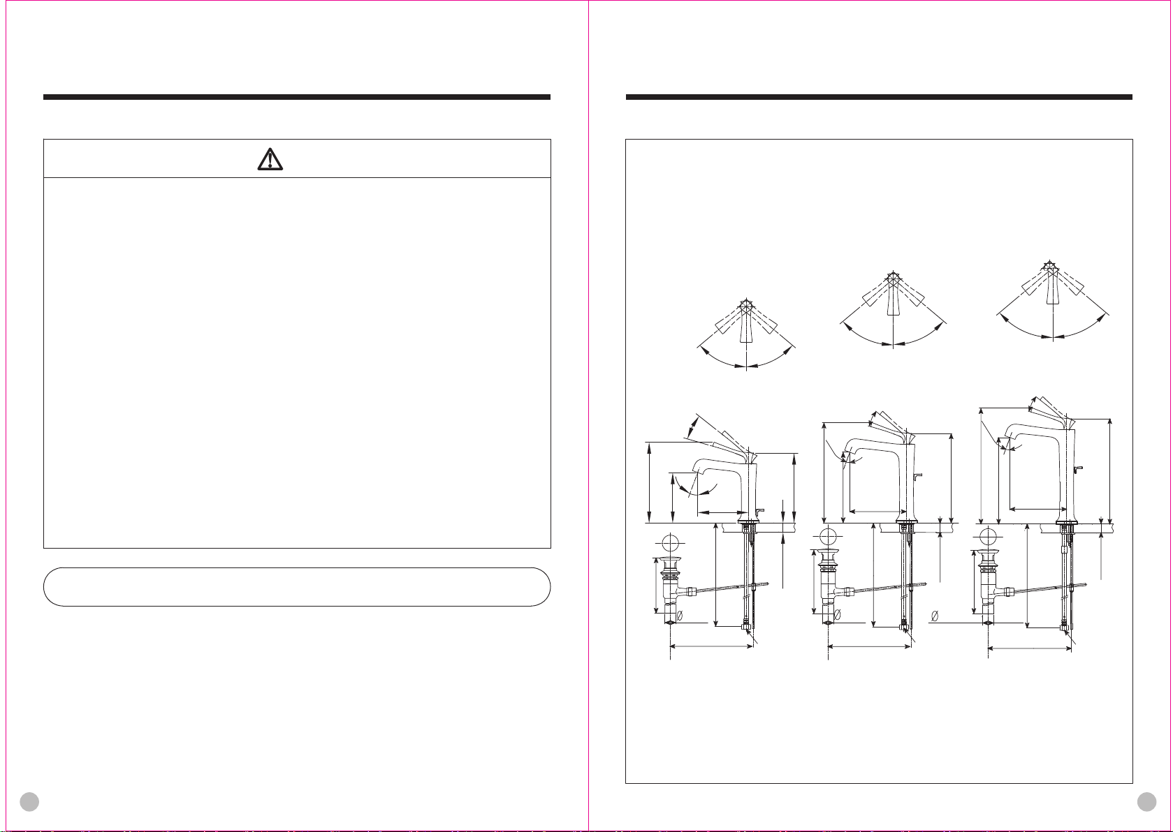
安装完成图
注意
1.由于陶瓷阀芯是较精密的部件,请勿擅自分解,否则可能会造成漏水
等不良。
2.请勿撞击本产品,否则可能会造成故障、漏水。
3.必须使用中性洗涤剂清洗,中性以外的洗涤剂会破坏镀层或使表面变
色。
4.不得使用酸性洗涤剂和去污粉、抛光粉等含粗颗粒的洗涤剂和尼龙刷,
否则可能会破坏镀层等。
5.可使用软布擦拭,间或用机油或车用蜡浸布擦拭,但请勿接触树脂部
件,否则可能失去光泽和产生锈蚀。
6.建议不要长时间不使用,否则可能会导致水嘴内部以及外部锈蚀不能
使用等现象。
7.如果吐水压力大,请调节止水阀达到需要的流量,避免水势过大,溅
出洗面盆。
8.随着产品式样的不断更新,实物存在与图示不符的情况,但基本安装、
使用原理相同。
9.由于说明书共通使用,已有产品型号可能不在说明书中体现,但安装、
使用原理相同。
DL367 铜合金台式单柄双控洗面器水嘴(含排水配件)
DL367-1 铜合金台式单柄双控洗面器水嘴(含排水配件)
DL367-2 铜合金台式单柄双控洗面器水嘴(含排水配件)
热水 冷水
50
。
混合水
。
开
22
20
闭
。
(297)
(230)
221.5
145
热水 冷水
50
。
混合水
开
。
22
闭
22
130
。
130
207
50
。
热水 冷水
50
。
混合水
。
开
22
闭
20
。
(257)
180
181.5
145
50
。
50
。
(270)
MAX35
G1/2
保养
为长期保持产品的美观,请用户按以下方法维护保养。
1.经常用软布擦拭,间或用软布蘸水擦拭。
2.当有污垢且比较明显时,请用中性洗涤剂擦拭后充分进行水洗。
(578)
(205)
31.75
(270) (290)
DL367 DL367-1 DL367-2
注:上记尺寸单位为mm;()内尺寸为参考尺寸。
G1/2
MAX35
(510)
(248)
31.75
MAX35
31.75
G1/2
(470)
(248)
(290)
5 6
Page 5

安装完成图
水嘴的安装
1.水嘴主体部分的安装
DL368 铜合金台式单柄双控洗面器水嘴(含排水配件)
DL368-1 铜合金台式单柄双控洗面器水嘴(含排水配件)
DL368-2 铜合金台式单柄双控洗面器水嘴(含排水配件)
红色 蓝色
红色 蓝色
红色 蓝色
约45
混合水
开
。
22
闭
。
10
42
130
104.5
。
约45
(168)
冷水热水
。
闭
。
10
164.5
约45
混合水
开
。
22
42
150
。
约45
(228)
冷水热水
。
闭
。
10
214.5
约45
开
。
22
42
170
。
混合水
约45
(278)
冷水热水
。
①如图所示,卸下主体下部的
固定螺母和马蹄形垫片。
②调整主体方向使其正面朝前
安装在洗面盆上。
③从洗面盆的下部用马蹄形垫
片和固定螺母将水嘴固定在
洗面盆上。
洗面盆
马蹄形垫片
配带限流附件场合
六角螺母
(582)
(205)
31.75
(270)
注:上记尺寸单位为mm;()内尺寸为参考尺寸。
5~35
(248)
G1/2 G1/2
(500)
31.75
(290)
7
5~35
(248)
31.75
(290)
(450)
DL368-2DL368-1DL368
5~35
G1/2
限流
附件
紧固螺母
注意:接入供水管前,务必确认紧固螺母内有无过滤垫片。
紧固螺母与进水管连接时,请使用止水阀连接。
有限流附件情况下,安装时先将接手拆下后安装到客户备用管,
再安装耐压软管。
耐压软管在出厂前已组装好,所以客户在安装使用时请勿拧动
六角螺母。
为了不使主体松动,请拧紧固定螺母。
不同示例产品的安装原理基本相同。
固定螺母
8
Page 6

水嘴的安装
排水金具的安装(示例)
水嘴的安装
①排水主体的安装 ③提拉杆的安装
塞盖
排水头
a.把排水头和密封圈从排水主体
上卸下。
b.然后把排水主体从面盆下面放
入。
c.从面盆上面将排水头和密封圈
组合到排水主体上。
d.调节安装杠杆螺纹孔的方向,
使其正对墙壁。
e.将螺母拧至合适的位置,避免
面盆破损。
②排水杠杆的安装
杠杆孔
止水塞
a.请注意止水塞的方向。
b.将杠杆经过杠杆孔,插
入到止水塞孔中,然后把
螺母旋紧。
密封圈
螺母
垫圈
垫圈
杠杆螺
纹孔
螺母
杠杆
拉杆
螺丝
连接滑块
杠杆
a.如图所示:先将杠杆穿过连接滑
块,然后用连接螺母将提拉杆与
连接杆固定,再调整连接滑块的
位置,使杠杆与止水塞处于合适
位置并用螺丝固定。
b.如果止水塞不能正常升降,请客
户自行调节连接滑块在连接杆与
杠杆上的位置。
注意:当排水中心
与拉杆中心距小于
150mm时,可能出现
操作力过大,可将
拉杆弯曲增加中心
距离减小拉杆操作
力。
螺丝
阀芯为可调温度阀芯时,温度调整方法。
将手柄卸下,把上部灰色调温环拔出,顺时针方向旋转,限制高温(
冷水 混合水);逆时针方向旋转,限制低温(混合水 热水)具体
挡块位置请参考下图。
注意:请小心设定,避免高温烫伤
高温环
顺时针旋转
(限制高温)
调温环
挡块位置 挡块位置 挡块位置
60℃
逆时针旋转限状 出厂状态 顺时针旋转极限状
注意:温度为参考值,入水温度参考值为:Tc=25℃ Th=60℃
(45
。
60℃
)
41℃
(45
。
)
41℃
逆时针旋转
(限制低温)
挡块
(出厂时位
于正前方)
。
)
(45
25℃
41℃
(45
。
)
25℃
9
10
Page 7

生产厂家与销售商
Contents
执行标准:GB 18145-2014、GB 25501-2010
产品型号:见包装箱上的标签
产品名称:见包装箱上的标签
生产日期:见包装箱上的标签
组装工厂:东陶(大连)有限公司
电 话:(0411)87624383
厂 址:大连经济技术开发区东北二街17号
800-820-9787
400-820-9787
Contents
Contents………………………………
Detailed list……………………………
Use conditions and attentions
in construction…………………………
Attentions in construction and
maintenance …………………………
Installation completion figure ………
Water nozzle installation……………
1
2-3
4
5
6-7
8-10
11
Manufacturer and vendor……………
11
1
Page 8

Detailed list
Detailed list
Detailed list
Main body of water nozzle ……………1 set
Flat plate drawbar………………………1 piece
Kickback lever …………………………1 piece
Water drainage fittings…………………1 set
Instructions for construction …………1 copy
Instructions for operation………………1 copy
The products using this detailed list include:
DL367 Single Lavatory Faucet with Popup
(including water drainage accessories)
DL367-1#PG Single Lavatory Faucet with Popup
(including water drainage accessories)
DL367-2 Single Lavatory Faucet with Popup
(including water drainage accessories)
DL367-2#PG Single Lavatory Faucet with Popup
(including water drainage accessories)
DL368 Single Lavatory Faucet with Popup
(including water drainage accessories)
DL368-1 Single Lavatory Faucet with Popup
(including water drainage accessories)
DL368-2 Single Lavatory Faucet with Popup
(including water drainage accessories)
DL367#PG Single Lavatory Faucet with Popup
(including water drainage accessories)
DL367-1 Single Lavatory Faucet with Popup
(including water drainage accessories)
2
3
Page 9

Use condition and attentions in construction
Use condition
Attentions in use and maintenance
1. Cold water supply*hot water supply pressure
Minimum pressure
Maximum pressure
2. The temperature for water supply is 4~90℃. It is suggested to use the hot water
temperature of 60±5℃. Do not use steam to supply hot water.
3. The ambient temperature for use is above 0℃. If the ambient temperature is lower
than0℃,the faucet will deform and crack from freezing.
4. Being out of use for a long time may result in internal and external rust to the faucet
and being unable to be used.
5. If you want to scrap this product, do not treat it as you do for general household
garbage. Please follow relevant statutes to have it treated, recovered and collected
appropriately by an independent recovery system.
6. The product in these instructions has a cleaning function.
Warning:it means that ignoring this mark and misoperation may cause serious
personal injury and death.
Attention: it means that ignoring this mark and misoperation may cause
personal injury or property loss.
1. The hot water supply side of the faucet is in a condition of high
temperature. Do not allow skin to contact with the hardware surface
directly. Otherwise, scalding may occur.
2. Do not reverse cold*hot water pipes. Otherwise scalding may occur.
3. Do not use steam to supply hot water. Otherwise, scalding may occur.
4. If a customer fails to use the self-contained water inlet filter net of our
water faucet, there is such a risk as water leakage or damage due to
foreign matters entering into the spool.
…………………
…………………
0.05MPa (flow pressure)
1.0MPa (static pressure)
Attentions in construction
Warning
1. As the ceramic cartridge is a precise component, do not dismantle it
without authorization.Otherwise, such poor conditions as water
leakage, etc. may be caused.
2. Do not impact the product. Otherwise, failure, water leakage may occur.
3. It is imperative to use a neutral detergent cleaning.Other detergents
than a neutral one may damage the plating coat or make the surface
discolor.
4. Do not use any such detergent as acidic detergent and
abstergent,polishing powder.etc containing thick particles and nylon
brush.Otherwise,the plating coat may be damaged etc.
5. It is allowed to use a piece of soft cloth to wipe or use from time to time
a piece of cloth immersed in machine oil or vehicle wax to
wipe.However,do not contact with resin components.Otherwise,they
may lose the gloss and become rusty.
6. It is suggested not to leave it unused for a long time.Otherwise,this may
lead to intemal and external rust to faucets to such a degree that it
cannot be used any more,etc.
7. If water pressure disgorges a large pressure,please adjust the water
stop valve to attain the required flow to avoid water flow being too high
to splash out from the face wash basin.
8. With the product design being updated constantly, the physical object
may not coincide with the figure. However, the basic principle for
installation, use is the same.
9. As the manual of instructions is for common use,the existing product
models may not appear therein.However,the principle for
installation,use is the same.
To maintain a beautiful appearance of the product, the user is requested to
conduct maintenance and care in the following method.
1. Wipe with a piece of soft cloth frequently and use a piece of soft cloth
dipped in water to wipe from time to time.
2. When dirt exists obviously, please use water to wash sufficiently after
wiping wife a neutral detergent.
Attentions
Maintenance
4 5
Page 10

Installation completion figure
Installation completion figure
DL367 Single Lavatory Faucet with Popup
(including water drainage accessories)
DL367-1 Single Lavatory Faucet with Popup
(including water drainage accessories)
DL367-2 Single Lavatory Faucet with Popup
(including water drainage accessories)
Hot water
。
22
Close
20
207
。
130
。
50
Mixed water
Open
130
50
。
Hot water
Cold
water
20
(257)
180
。
50
Mixed water
Open
。
22
Close
。
181.5
145
50
。
Hot water
Cold
water
20
(297)
(230)
50
Mixed water
。
22
Close
。
221.5
145
。
Open
50
。
Cold
water
(270)
DL368 Single Lavatory Faucet with Popup
(including water drainage accessories)
DL368-1 Single Lavatory Faucet with Popup
(including water drainage accessories)
DL368-2 Single Lavatory Faucet with Popup
(including water drainage accessories)
Red Blue
Red Blue
Red Blue
Hot water
Around
45
。
22
Close
。
10
130
104.5
。
Mixed water
Open
42
。
Around
45
(168)
Hot water
Cold water
164.5
Around
。
45
Mixed water
。
Open
22
Close
。
10
42
150
Cold water
。
Around
45
(228)
Hot water
Close
。
10
214.5
Around
。
22
170
。
45
Open
Around
45
Mixed water
42
(278)
Cold
water
。
(578)
(205)
31.75
(270)
DL367 DL367-1 DL367-2
Note: The unit of the above dimensions is mm.
The dimensions in () are reference dimensions.
MAX35
(248)
G1/2
(510)
31.75
(290)
6
G1/2
MAX35
(248)
31.75
(470)
(290)
G1/2
MAX35
5~35
(582)
(205)
31.75
(270)
Note: The unit of the above dimensions is mm.
The dimensions in () are reference dimensions.
(248)
G1/2 G1/2
(500)
31.75
(290)
5~35
(248)
(450)
31.75
(290)
5~35
G1/2
DL368-2DL368-1DL368
7
Page 11

Water nozzle installation
Water nozzle installation
1.Installation of main body of water nozzle
As shown in the diagram, remove
①
2.Installation of water drainage fittings(example)
①
the securing nut and horseshoeshaped gasket in the lower part of
the body.
Adjust the direction of the body
②
so that it is installed on the face
wash basin with the front side
facing forward.
Use horseshoe-shaped gasket
③
and securing nut to fix the water
Face wash basin
nozzle onto the face wash basin
from the lower part thereof.
Horseshoe
shaped gasket
Occasion provided with a
flow-limiting accessory
Flowlimiting
accessory
Hexagonal nut
Securing the nut
②
Fastening nut
Attentions:Before connecting into the water supply pipe,be sure to confirm if filter
gasket is available in the fastening nut.
When connecting the fastening nut with water inlet pipe,please use water stop
valve for connection.
Whe installing,first remove the connecting hand and install to the standby pipe
of customer,then install the pressure-resistant hose.
The pressure-resistant hose has been installed before ex-factory.Therefore,
customer is not allowed to screw the hexagonal nut when install and use.
In order to keep the main body from loosening,please screw tight the securing
nut.
The product installation principle is basically the same for different examples.
Installation of main drainage body
Seal surface
Main water
drainage body
a.Remove the water drainage head and
seal ring from the main water drainage
body.
b.Then put the main water drainage body
in from the lower side of the face basin.
c.Combine the water drainage head and
seal ring onto the main water drainage
body from the upper side of the face
basin.
d.Adjust the direction of the screw hole to
install the lever so that it faces right
against the wall.
e.Screw the nut to an appropriate
position to avoid face basin being
damaged.
Washer
Nut
Lever screw
thread hole
Draw bar installation
③
Draw bar
Connecting
slide
Installation of water drainage plug
lever hole
Washer
Nut
Lever
a.As shown in the diagram,first put the
lever through the connecting slide.
Then use connecting nut to secure
Water
stop
plug
Lever
the draw bar and connecting bar.
Adjust the position of the connecting
slide to make the lever and water stop
plug be in an appropriate position and
a.Please pay attention to the direction
of the water stop plug.
b.Insert the lever through the lever hole
into the water stop plug hole.Then
screw tight the nut.
secure with screw.
b.Iower nomally,customer is requested
to adjust the position of the connecting
slide on the connecting bar and lever
by himself.
Screw
Attentions:
distance between
the water drainage
center and the
draw bar center is
less than 150mm,
the operating force
may be too high.
The draw bar can
be bent to increase
the center distance
and reduce the
operating force of
the draw bar.
Screw
When the
8
9
Page 12

Water nozzle installation
Manufacturer and vendor
Temperature adjustment method when the valve core is one with temperature
adjustable.Remove the handle,unplug the upper grey temperature-adjusting ring
and rotate clockwise to limit high temperature(cold water?mixed water).Rotate
anticlockwise to limit low temperature(mixed water?hot water).For the specific
position of stopper,refer to the diagram below.
Applicable standard:GB 18145-2014、GB 25501-2010
Product Model No.:See the label on the packaging case
Product name:See the label on the packaging case
Production date:See the label on the packaging case
Attentions:Please set carefully to avoid scalding due to high temperature.
Assembly factory:TOTO(Dalian)Co.,Ltd.
Rotate clockwise
(limiting high temperature)
Temperatureadjusting ring
Temperature-adjusting ring
Rotate anticlockwise
(limiting low temperature)
Stopper
(located right
ahead on
ex-factory)
Telephone:(0411)87624383
Factory address:17 Dong Bei Second Street,Economic&Technical Development
Zone,Dalian
TOTO(China)Co.,Ltd.
National toll-free after-sale service telephone:
Stopper
position
Stopper
position
Stopper
position
800-820-9787(fixed telephone dialing)
400-820-9787(mobile phone dialing)
60℃
Anticlockwise rotation limit condition
(45
。
)
60℃
41℃
Attentions:The temperature is a reference value. The water entry
temperature reference value is Tc = 25 oC, Th = 60 oC.
10
25℃
。
(45
)
41℃
Ex-factory condition
(45
。
)
Clockwise rotation limit condition
41℃
(45
。
Vendor:TOTO(China)Co.,Ltd.
Address:Room 1915,North Building of Beijing Jiali Center,
)
25℃
No.1,Guanghua Road,Chaoyang District,Beijing
Website:www.toto.com.cn
11
 Loading...