

Page 1
!
MiniLab
Side panel 2
!
Totem by UAB Aldrea
ver 1.0!
Page 2
w ww.totemmaker.net
Min iL ab Side Panel 2
Overview
This is a get ting started guide for a second expansion board for the Totem MiniLab
system. I n this document we’ll go over all of the available modules in the board, toget her
with explanati ons on their interface with the MiniLab as well as usage examples.
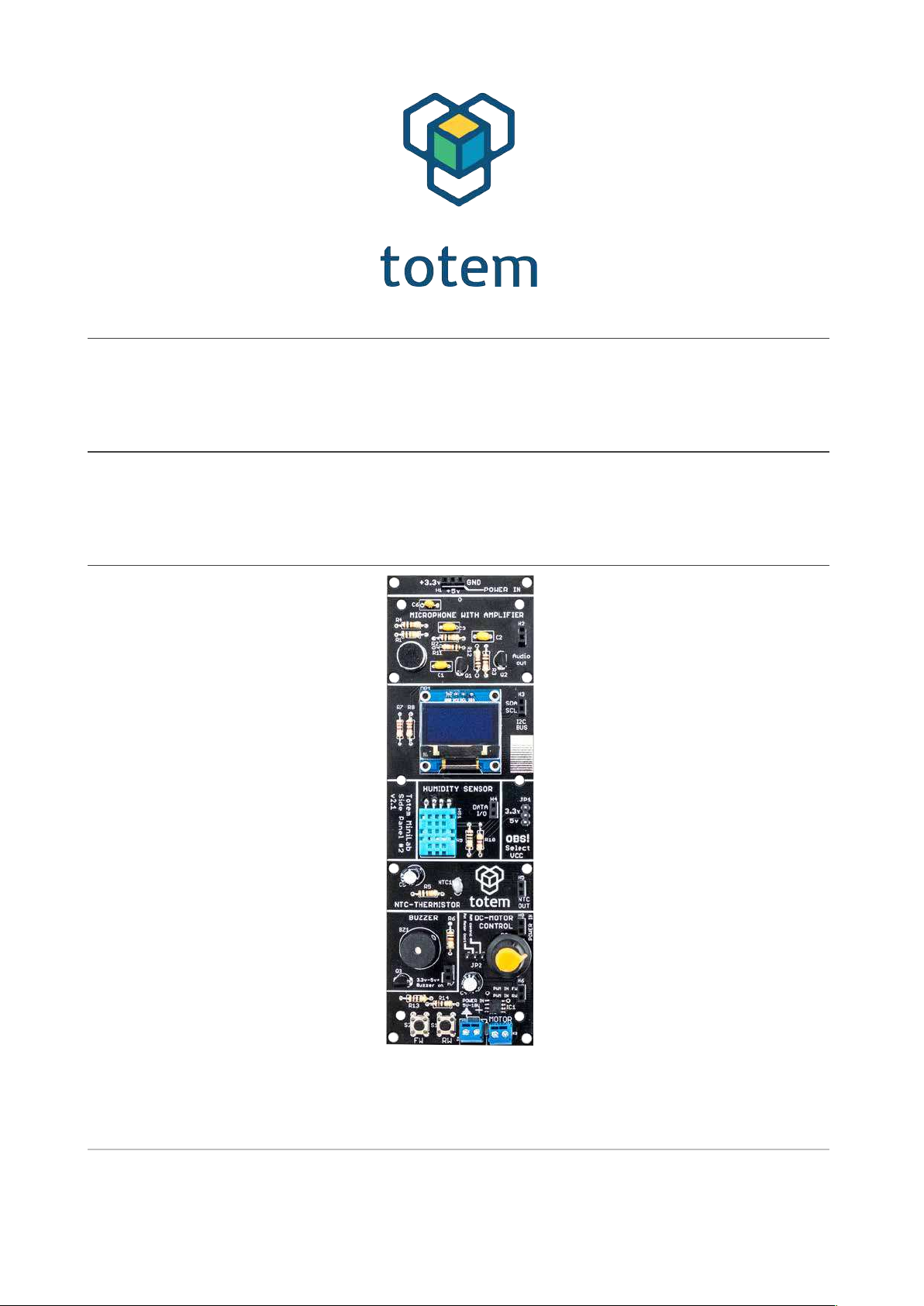
Side panels are meant to bring easy access to commonly used components that are
difficult to wire on breadboards due to their dimensions, or r equire additional equipment
to operate them. Side panels give a plug and play i nterface that lets users to concentrate
on experiments or learning, rather than spending time solvi ng issues on how to interface
with the part.
This document is divided into sections where each separate module i s descr ibed. In the
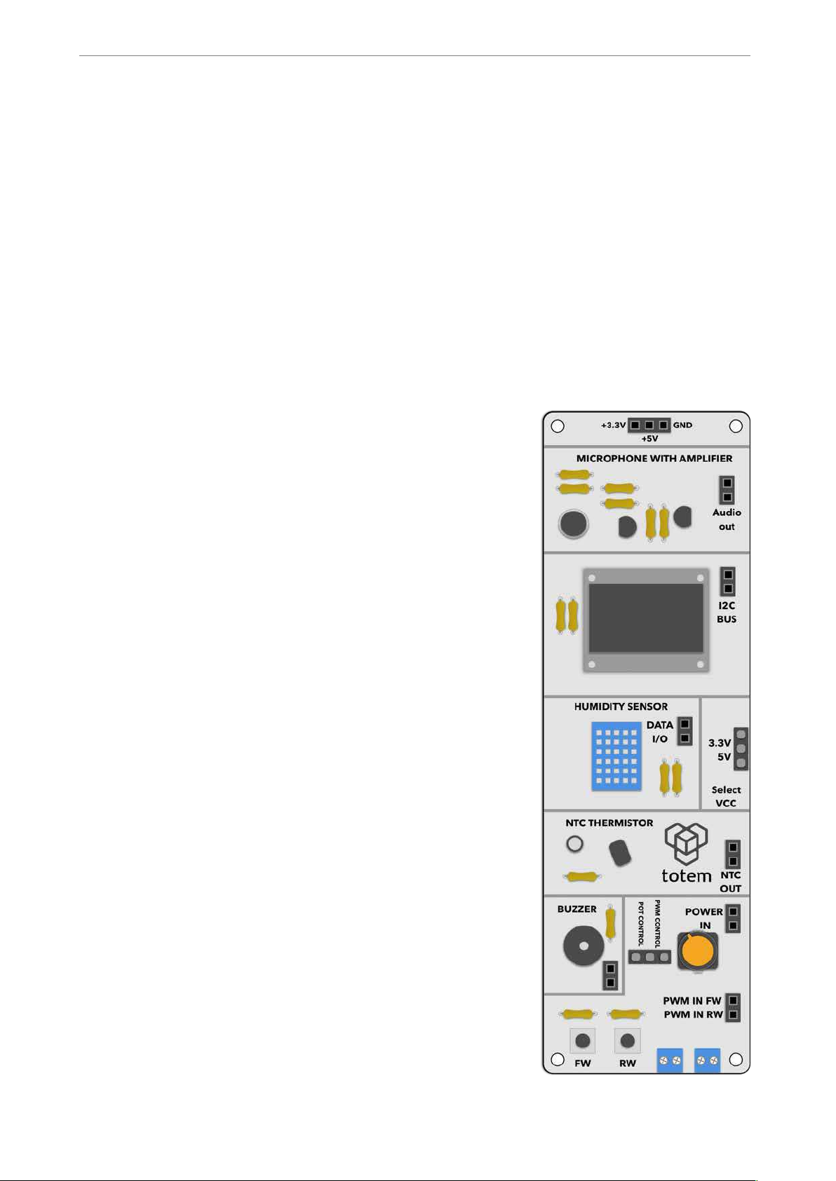
si de panel 2 these modules are available for use:
• M icr oph one — ready to use microphone module wi th
integrated preamplifier that outputs currently measured
sound pressur e i n 0 to (V
cc
- 2.5) Volt range.
• 12 8 x6 4 OLED display— monochrome gr aphical screen
controlled via I 2C interface. Uses SSD1306 chip as a
driver .
• DH T11 hum idity sensor — digital composite sensor
capable of measuri ng temperature and humidity. Uses
si ngle-wir e serial inter face for communication.
• NTC ther m istor — a simple 10k thermist or that in the
module works as a voltage divider, useful for making
temperature sensors.
• Piezo electr i c buzzer — beeper module with integr ated
transistor dr iver. Produces sound when high level signal
is applied.
• DC m otor dr iver module — an h-bridge motor driver
with integrated protections.
! of !2 11
Page 3
w ww.totem maker .net
Min iL ab Si de Panel 2
Modules
In the board only the supply power is shared bet ween modules. Otherwise they’re fully
isolated from one another, and can be used independently. Logic level for digital signals
have a jumper which selects the boards to work either at 3.3 or 5 V logic level. It’s
important for the side panel to have the same logic level as the controller board (e.g.,
TotemDuino), for best results.
Microphone
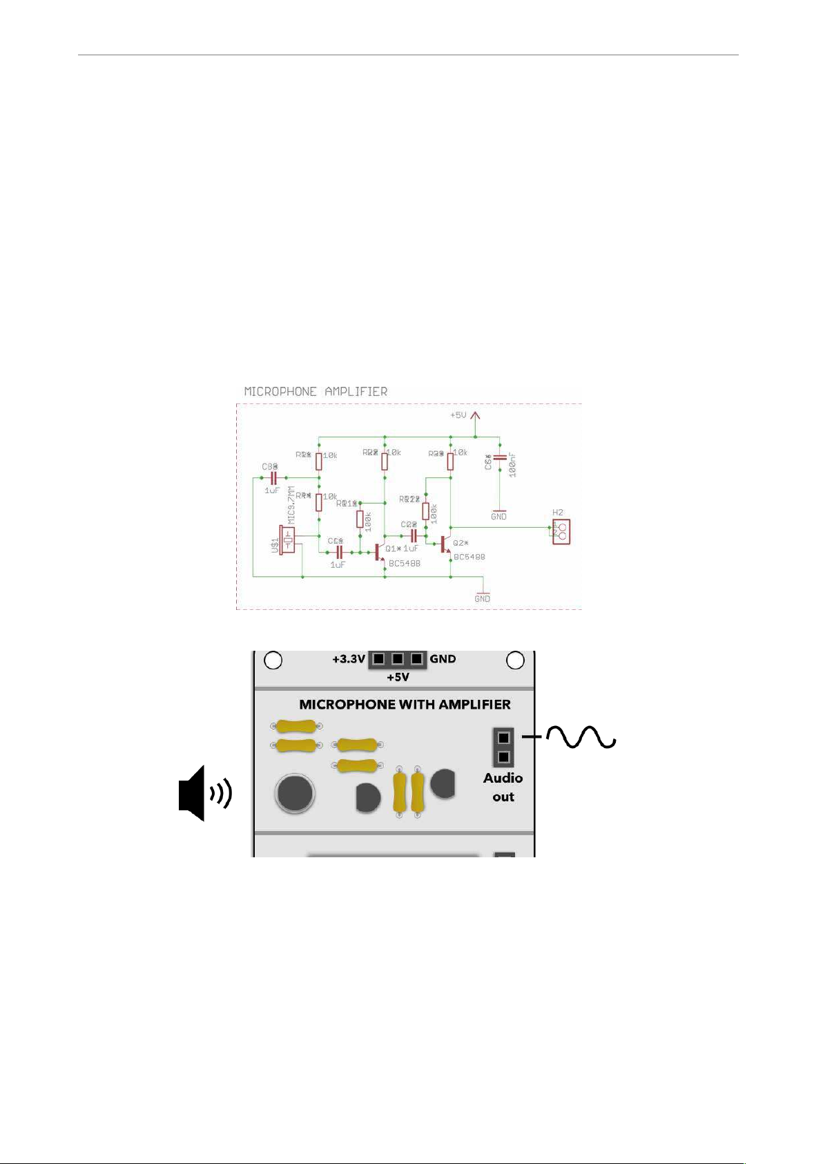
This module takes care of all things needed to dr ive t he microphone, and outputs an
analog signal in the 0 ..V cc range. Suggest ed uses for thi s module are readi ng the value
with TotemDuino, or using it as an input to operational amplifiers.
!
Fig. 1 Microphone module schematics
!
Display
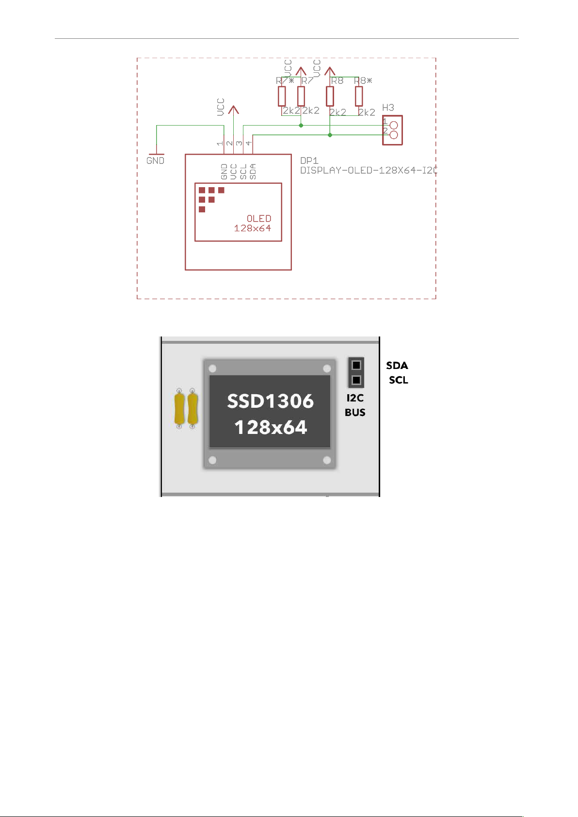
Screen uses a SSD1306 chip for control. I2C interface with integrated pull-up resi stors is
used to interface with the driver. Works with both 3.3 or 5 V supply voltages, selected by
jumper pin. Refer to t he SSD1306 datasheet for interface specifics, or to Totem examples
sketch for sample usage of the module.
! of !3 11
Page 4
w ww.totem maker .net
Min iL ab Si de Panel 2
!
Fig. 2 Display module schematics
!
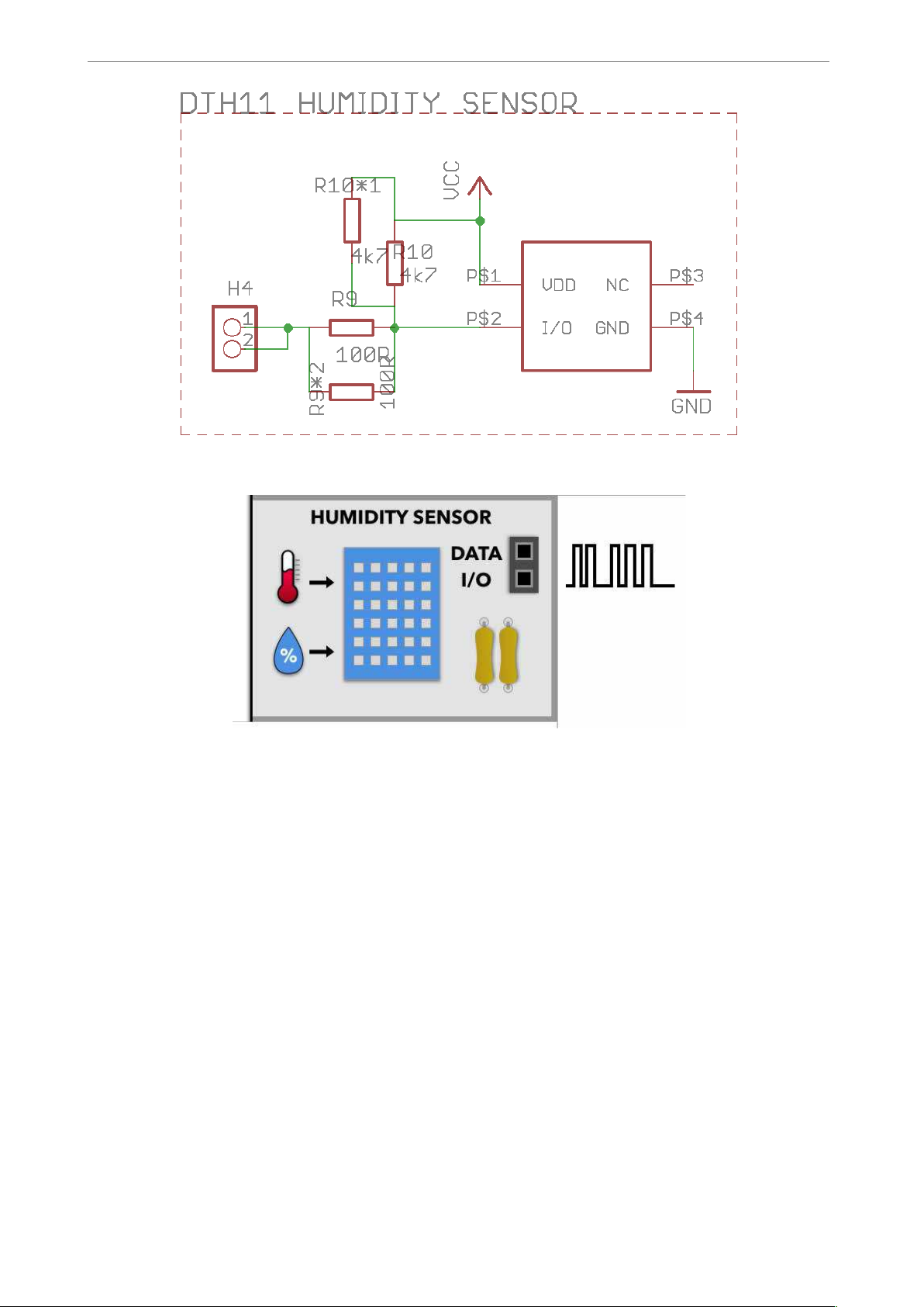
Humidity sensor
Digital, 16bit humidity and temperature sensor using one wire protocol. Accepted
temperature range of -40 to 80 °C with 0.5% accuracy and humidity fr om 0 to 100% at
2-5% accuracy.
Can be used with 3.3 V or 5 V supply voltages, selected by jumper pin.
! of !4 11
Page 5
w ww.totem maker .net
Min iL ab Si de Panel 2
!
Fig. 3 Humidity module schematics
!
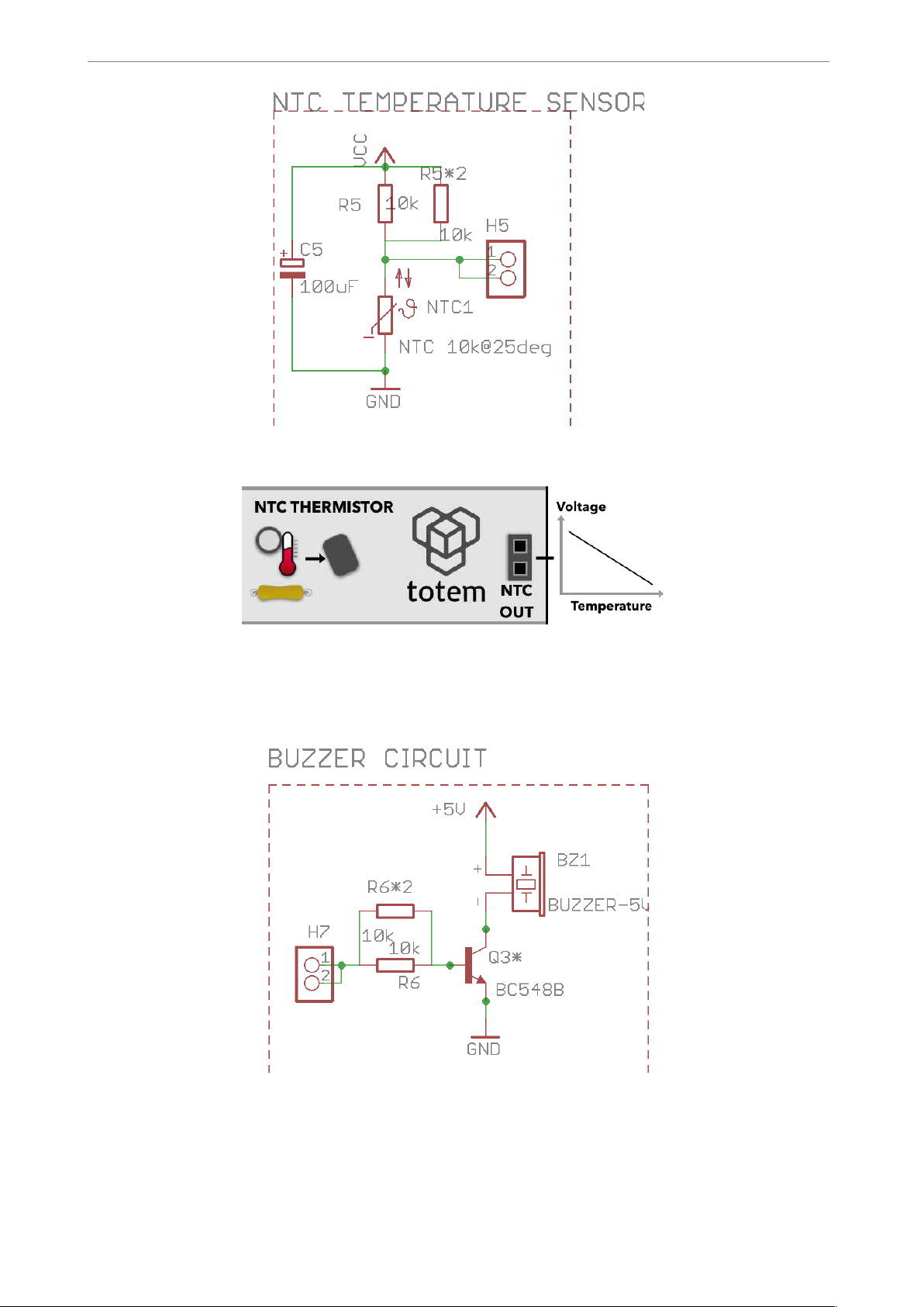
NTC thermistor
Negati ve temperatur e coefficient (NTC) ther mistor wor ki ng i n vol t age divi der
configuration. At r oom temperature (25 °C) has 10k resistance. Can be used from -40 to
125 °C temperature.
! of !5 11
Page 6
w ww.totem maker .net
Min iL ab Si de Panel 2
!
Fig. 4 Thermistor module schematics
!
Buzzer
An active piezo electric buzzer with transistor driver. Powered from 5V supply voltage.
Active logic level in it s i nput activates the buzzer.
!
Fig. 5 Buzzer module schematics
! of !6 11
Page 7

w ww.totem maker .net
Min iL ab Si de Panel 2
!
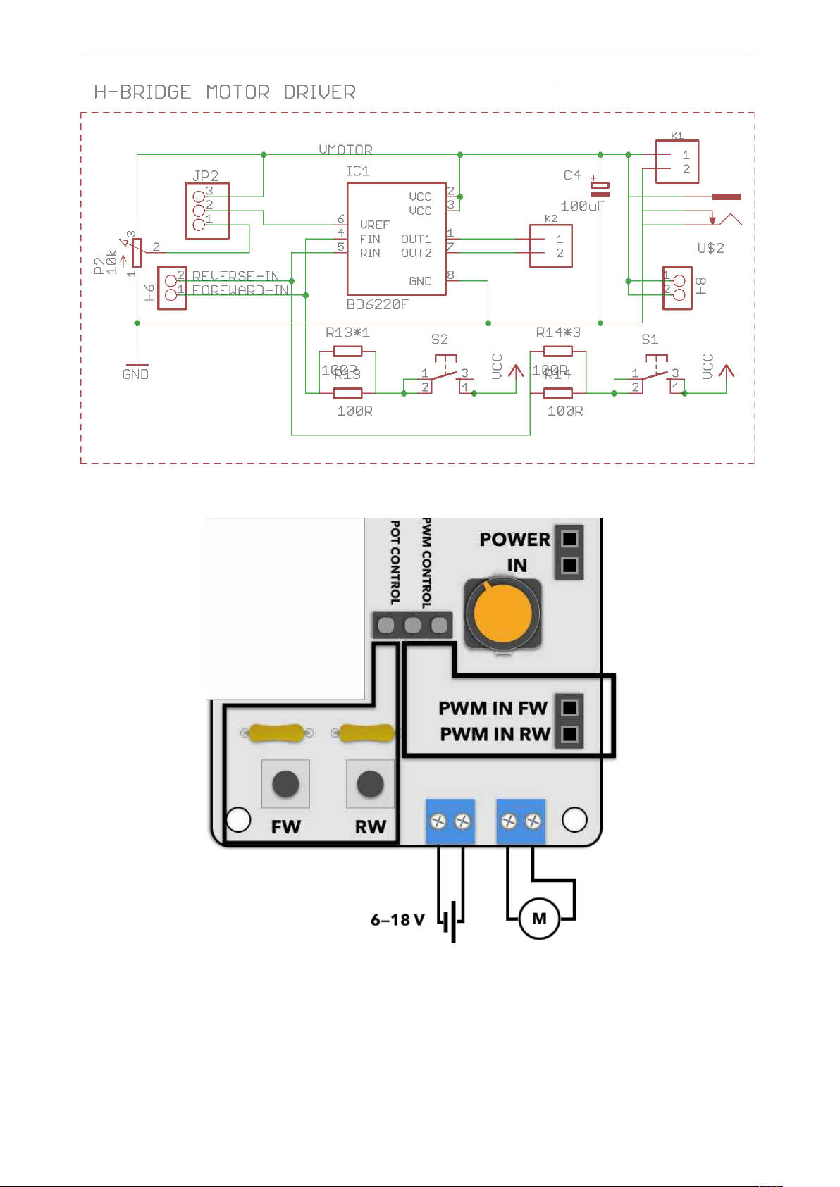
DC motor driver
An h-bridge motor driver powered by BD6220F chip. Can be controlled from int egrated
buttons and potentiometer or accepts logic level inputs. Can be used in pulse width
modulation (PWM) mode for cont rolling motor speed.
Depending on the i nput state, motor can recei ve four differ ent working modes:
Driver contains protections against over-curr ent, short-circuit conditions. Jumper JP2 on
the module controls the input refer ence (maximum voltage appli ed to the motor) source -
when in PW M con tr ol mode the r eference voltage equals supply voltage, when in Pot
M eter Cntrl mode the reference voltage is controlled by potentiometer.
Input A
Input B
Motor state
LOW
LOW
Idle
LOW
HIGH (PWM)
Rotation A
HIGH (PWM)
LOW
Rotation B
HIGH
HIGH
Brake
! of !7 11
Page 8
w ww.totem maker .net
Min iL ab Si de Panel 2
!
Fig. 6 Motor driver module schematics
!
! of !8 11
Page 9

w ww.totem maker .net
Min iL ab Si de Panel 2
Assembly
This section guides through the st eps for assembling your side panel.
Side panel 2 comes wit h the motor driver chip already soldered on the boar d, as this is an
SMD part which is a li ttle bit more diffi cult to solder than usual thr ough hole components.
As usual, we recommend starting your assembly fr om the smallest components such as
resistors, and working your way up with larger ones. That way when you fli p the board to
solder the contacts, they will not fall out from their place. Use the following guide for
assembly:
!
! of !9 11
Page 10
w ww.totem maker .net
Min iL ab Si de Panel 2
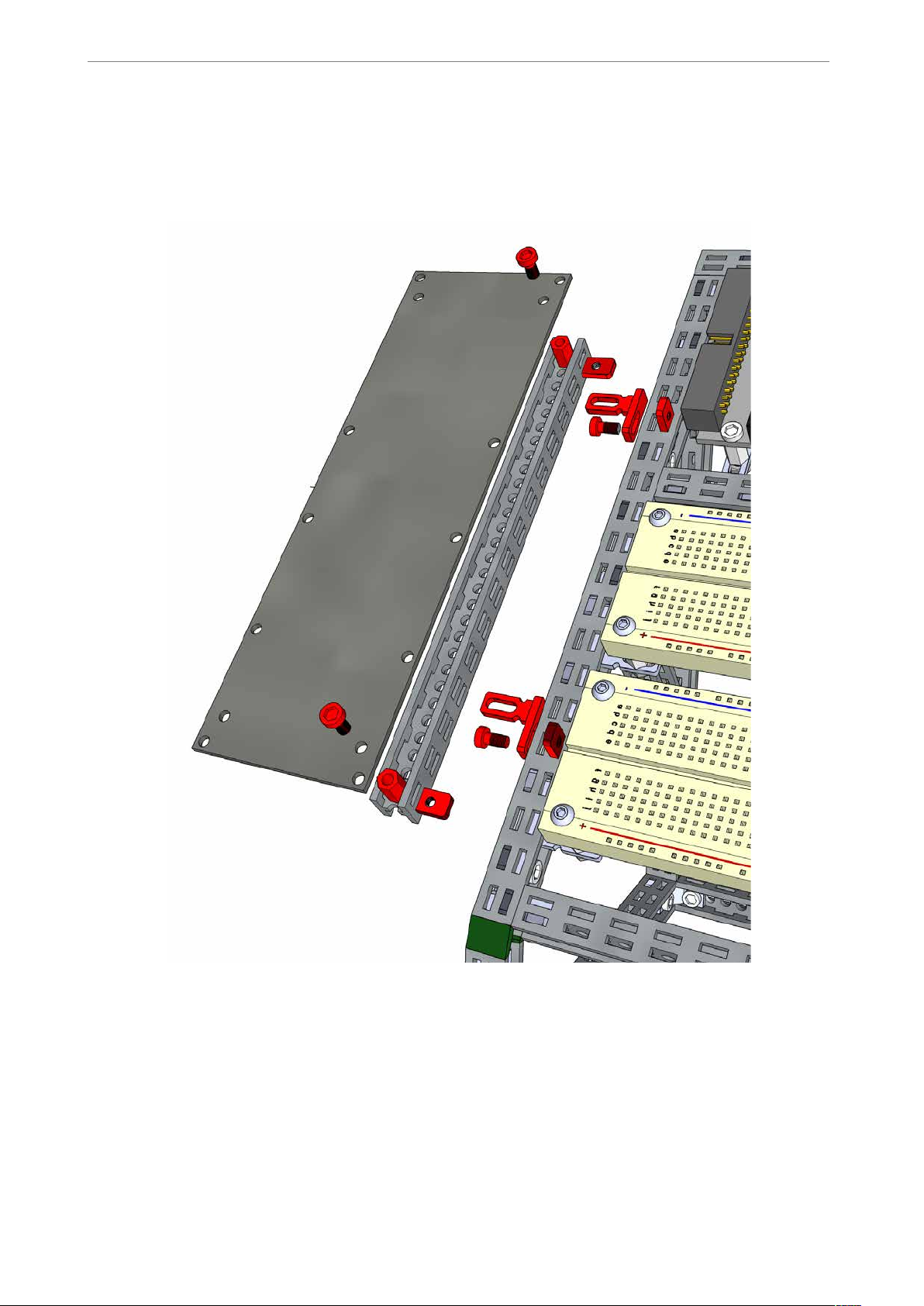
Mounting
We suggest using the following guide for side panel mounting to the MiniLab workbench:
In this case, the sub-assembly can be easily taken off by sliding the pins fr om the sockets.
If a more permanent assembly is needed, nuts and screws can be used to fix the sidepanel
in place.
! of !10 11
Page 11
w ww.totem maker .net
Min iL ab Si de Panel 2
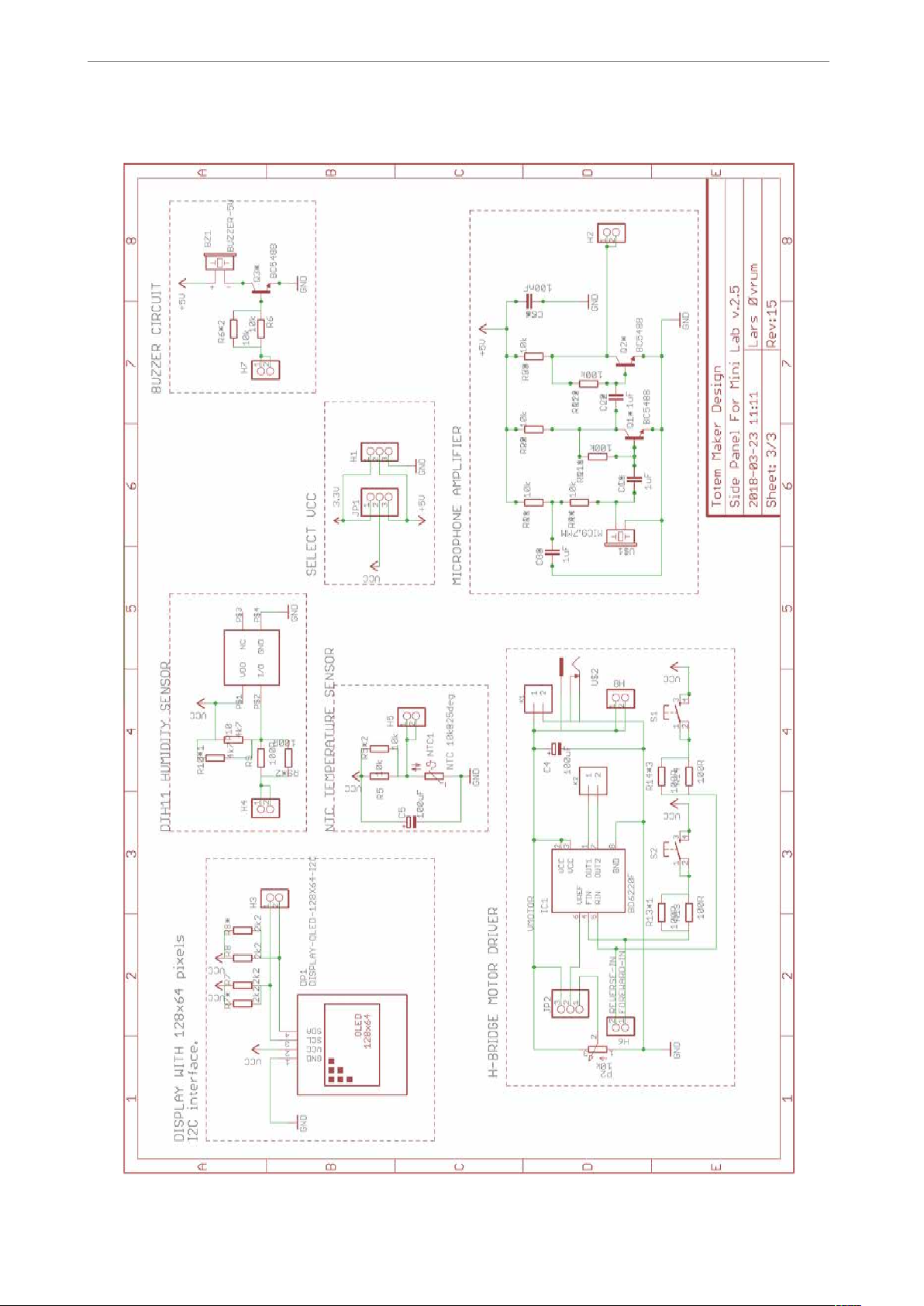
Schematic
!
! of !11 11
 Loading...