

Page 1

Page 2
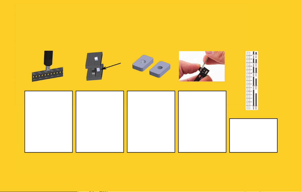
STARTING TIPS
Inserting nuts (1) Inserting nuts (2) Faulty threads Tightening
standoff s
It is a good idea to
start every step inserting nuts into
beams (if the step
requires).
Use the back of the
screwdriver to push
in the nuts.
After entering the
rst slot, nuts tend
to tilt. Use your
thumb to push it
back straight, and
then again use the
screwdriver to in-
sert the nut all the
way in.
For more tips, please visit the link below:
Some of the nuts
are missing threads.
This is a manufacturing issue and we
are working on it. In
the mean time, we
add few extra nuts.
We apologize for
the inconvenience.
Push Nylon
Standoff with your
thumb while tight-
ening it with the
wrench.
https://totemmaker.net/blog/totem-mechanics-for-beginners/
Ruler
Use Beam/Bolt
ruler to determine
the length of beams
and bolts.
Page 3

PART LIST
8x Beam 90 mm 4x Bolt M1.6x3 1x Bolt M2.5x12 24x Bolt M3x6 2x Bolt M3x8 2x Bolt M3x10
4x Bolt M3x20 2x Bolt M3x25 1x Bolt M3x45
5x Lock Nut M3 30x Nut M3 6x10 3x Nut M3 5.5x5.5 2x Nylon Standoff M3x8 5x Nylon Spacer 4 mm 4x Nylon Spacer 5 mm
3x Nylon Spacer 8 mm 3x Zip Tie 2x D-Shaft Wheel 2x O-Shaft Wheel 1x Mini Control Board 1x Rechargeable Battery
1x Rechargeable Battery
Charger
1x Mini Screwdriver 1x Totem Wrench 1x Totem Screwdriver
1x Mini Servo Motor 2x N20 Motor 2x N20 Motor Bracket
6x 2-Hole Simple
Bracket
4x 2-Hole 90 Bracket 2x L-Twisted Bracket
1x Mini Servo Motor
Bracket
1x Micro Gripper
Page 4
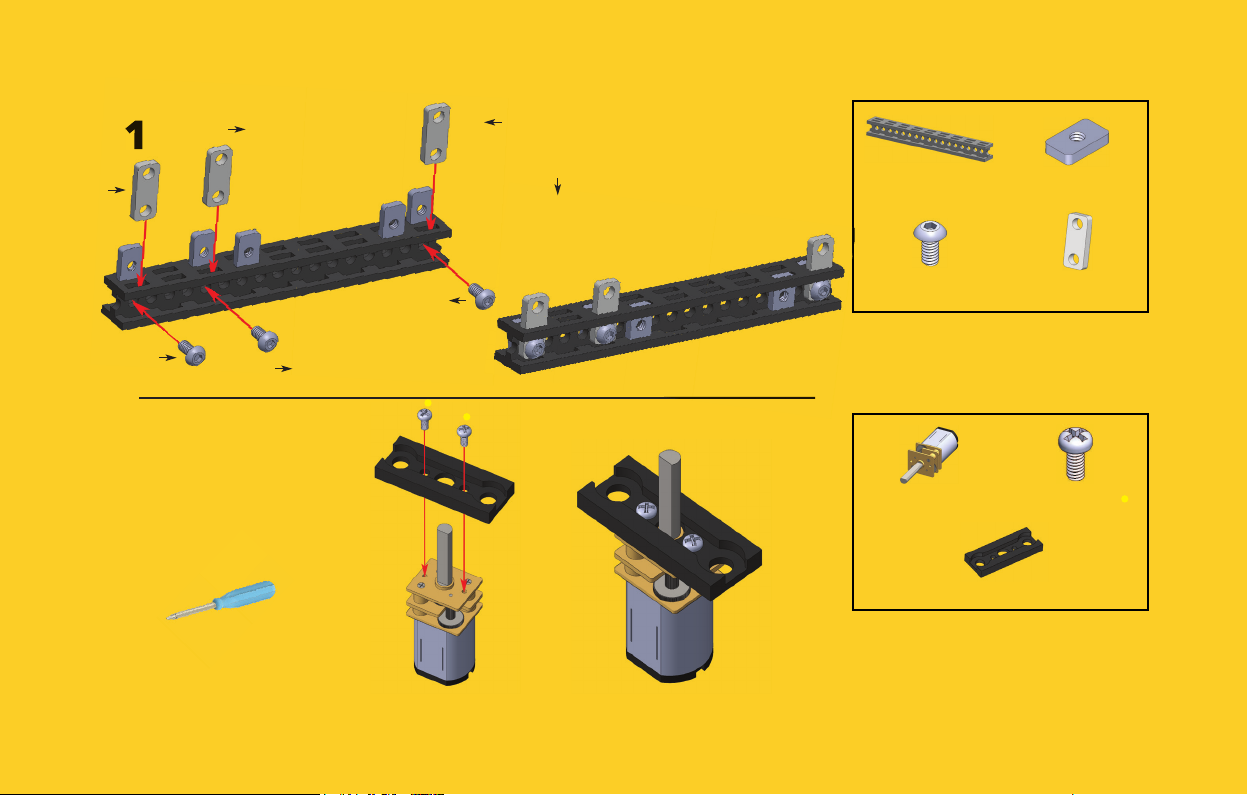
1
#3
#1
# indicates number
of slot.
#1
#1
#5
2
Use Mini Screwdriver
for the bolts.
#1
indicates counting
direction.
1x Beam 90 mm 5x Nut M3 6x10
3x Bolt M3x6
2x N20 Motor 4x Bolt M1.6x3
2x N20 Motor Bracket
3x 2-Hole Simple
Bracket
Repeat this step twice.
2x
Page 5
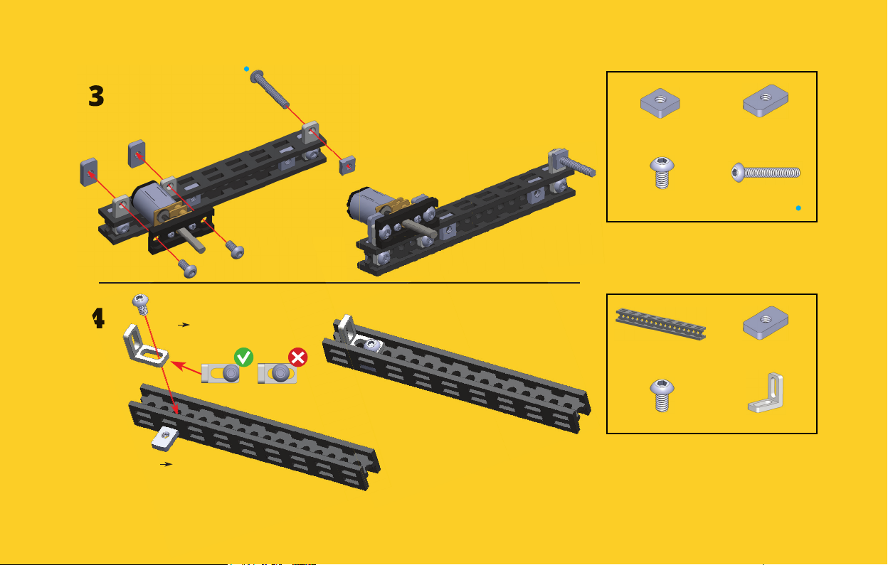
3
1x Nut M3 5.5x5.5 2x Nut M3 6x10
2x Bolt M3x6 1x Bolt M3x20
4
#3
2x Beam 90 mm 2x Nut M3 6x10
2x Bolt M3x6 2x 2-Hole 90 Bracket
Repeat this step twice.
#2
2x
Page 6
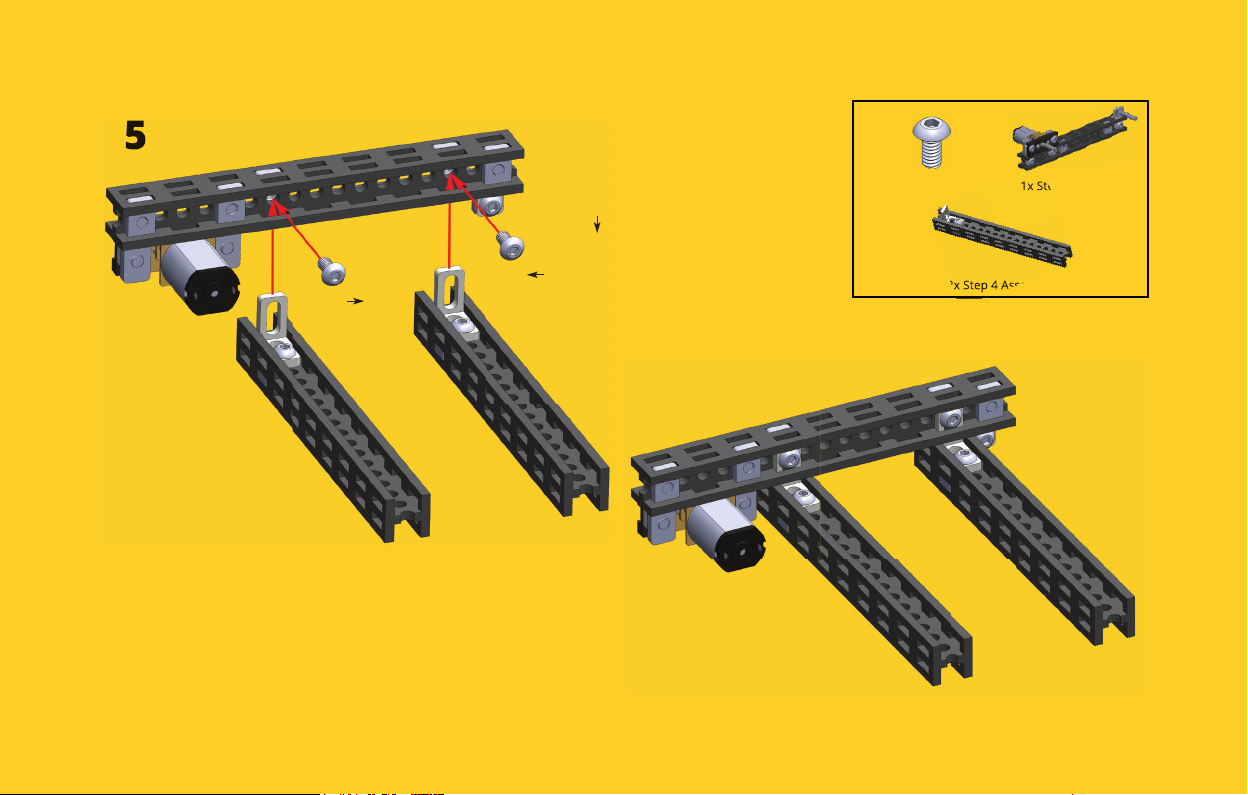
5
#7
#3
# indicates number
of slot.
indicates counting
direction.
2x Bolt M3x6 1x Step 3 Assembly
2x Step 4 Assembly
Page 7
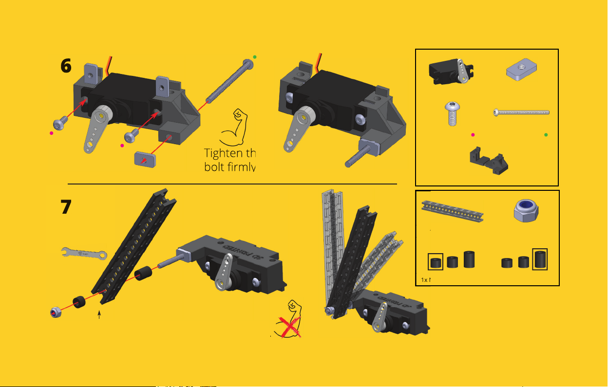
6
7
Use wrench for
Lock Nut.
#1
1x Mini Servo Motor 3x Nut M3 6x10
2x Bolt M3x8 1x Bolt M3x45
Tighten the
bolt rmly.
1x Mini Servo Motor Bracket
1x Beam 90 mm 1x Lock Nut M3
1x Nylon Spacer 4 mm 1x Nylon Spacer 8 mm
Tighten the Lock Nut just
enough to get a smooth
hinge rotation movement.
Page 8
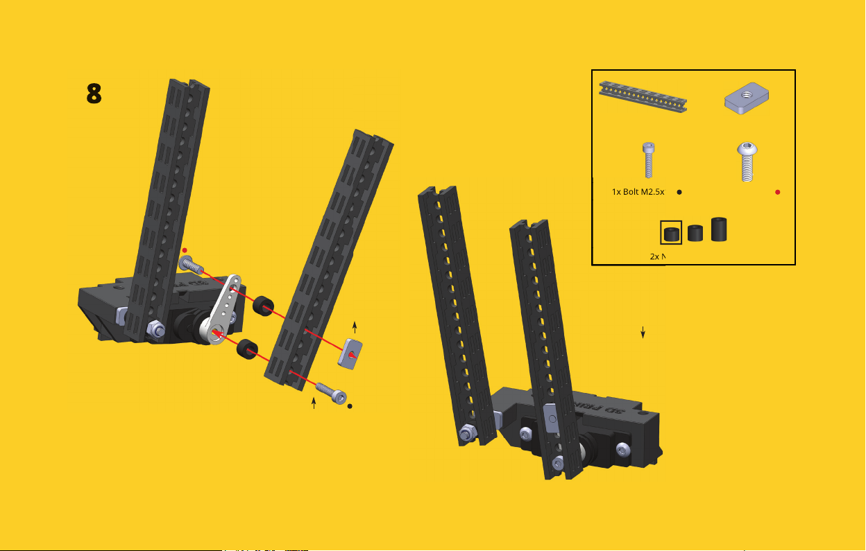
8
1x Beam 90 mm 1x Nut M3 6x10
1x Bolt M2.5x12 1x Bolt M3x10
2x Nylon Spacer 4 mm
# indicates number
of slot.
#1
#4
indicates counting
direction.
Page 9
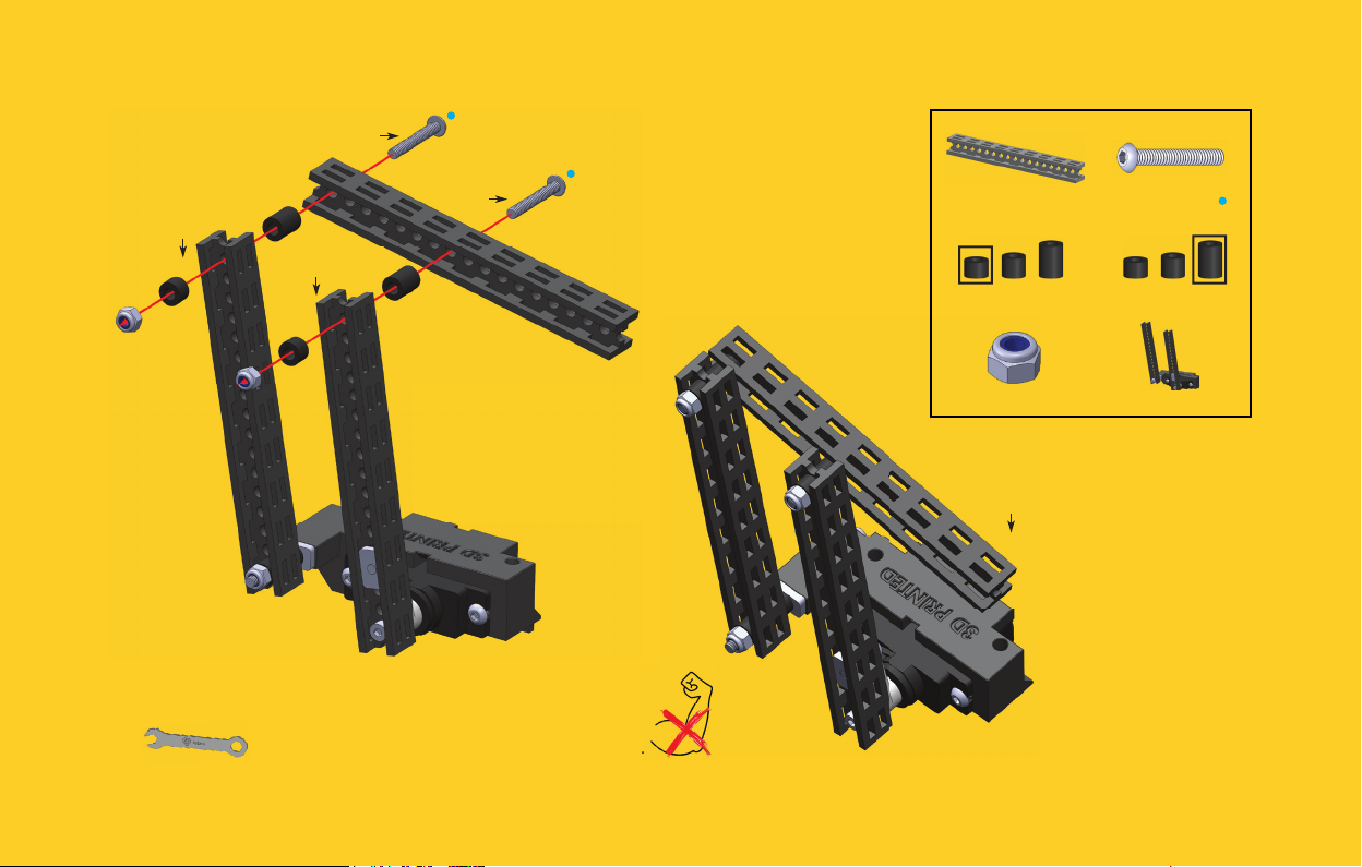
9
#1
#1
#1
Use wrench for
Lock Nuts.
#8
Tighten the Lock Nut just
enough to get a smooth
hinge rotation movement.
1x Beam 90 mm 2x Bolt M3x20
2x Nylon Spacer 4 mm 2x Nylon Spacer 8 mm
2x Lock Nut M3 1x Step 8 Assembly
# indicates number
of circular slot.
indicates counting
direction.
Page 10
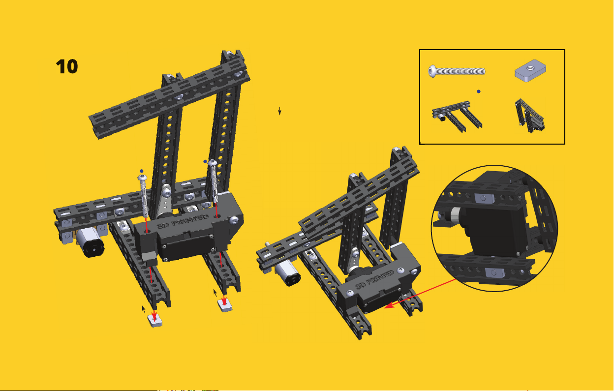
10
#4
#4
# indicates number
of slot.
indicates counting
direction.
2x Bolt M3x25 2x Nut M3 6x10
1x Step 5 Assembly 1x Step 9 Assembly
Bottom view.
Page 11
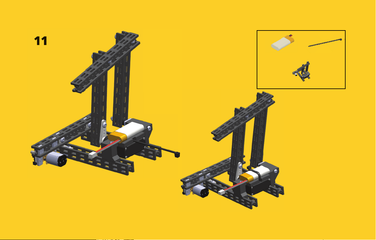
11
1x Rechargeable Battery 1x Zip Tie 100 mm
1x Step 10 Assembly
Page 12
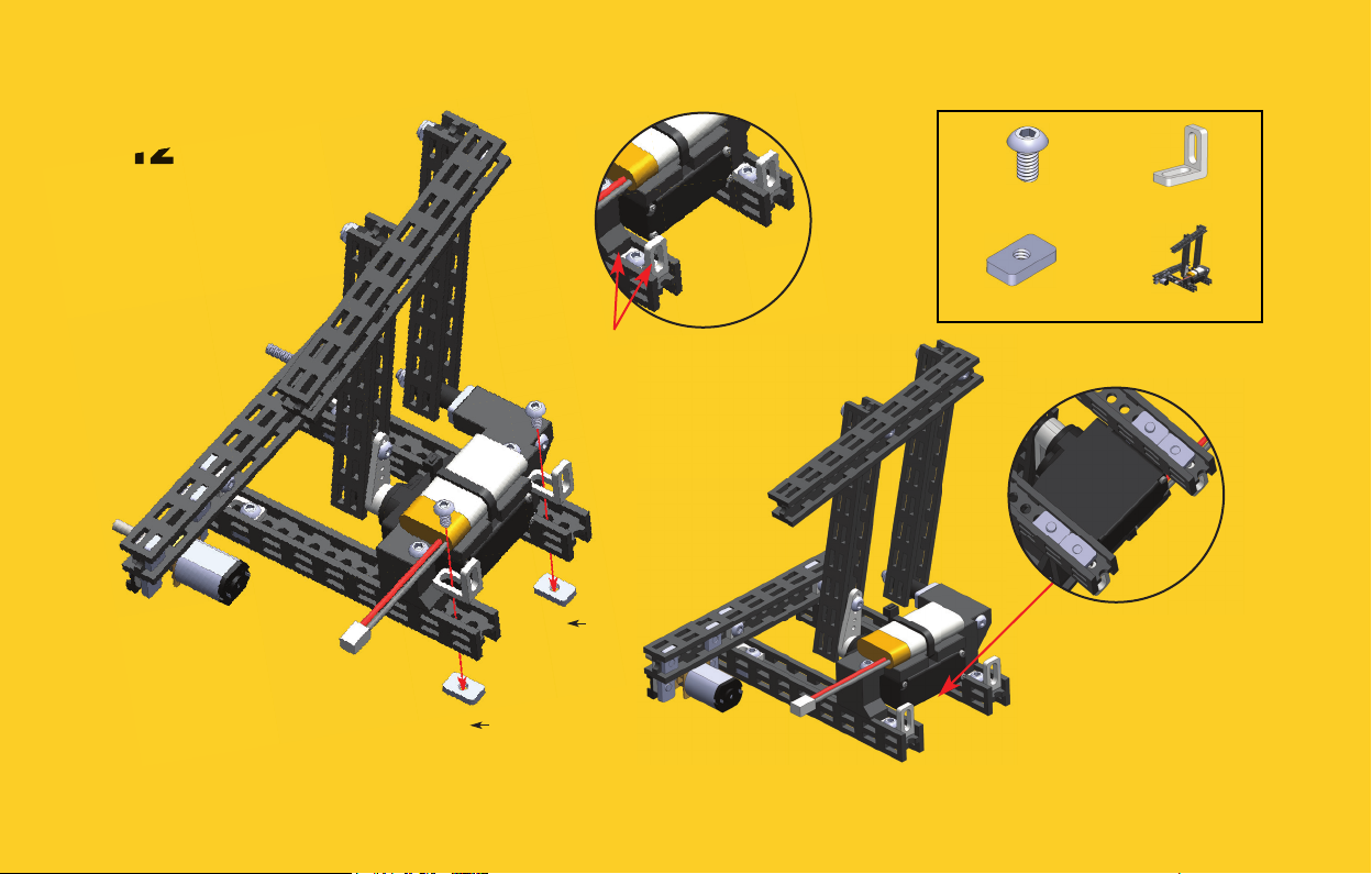
12
2x Bolt M3x6 2x 2-Hole 90 Bracket
2x Nut M3 6x10 1x Step 11 Assembly
2-Hole 90 Brackets
must touch the
motor bracket.
#2
#2
Bottom view.
Page 13
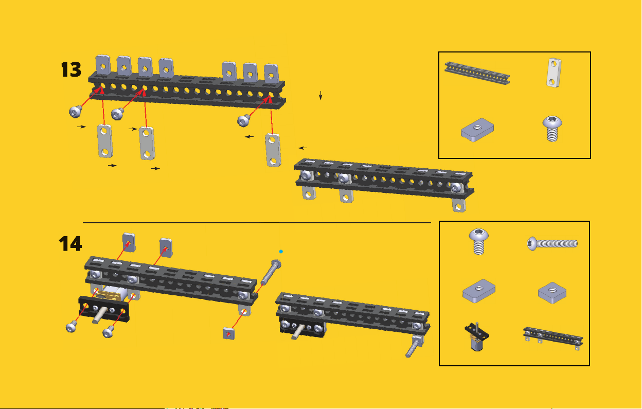
13
# indicates number
of slot.
#1
14
#1
#5
#3
#1
#1
indicates counting
direction.
1x Beam 90 mm
7x Nut M3 6x10 3x Bolt M3x6
2x Bolt M3x6 1x Bolt M3x20
2x Nut M3 6x10 1x Nut M3 5.5x5.5
1x Step 2 Assembly 1x Step 13 Assembly
3x 2-Hole Simple
Bracket
Page 14
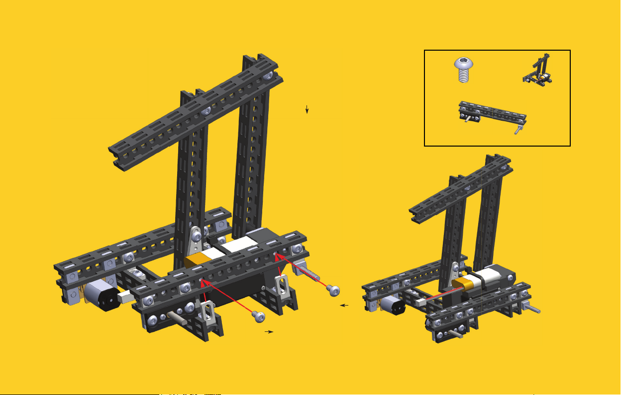
15
#7
# indicates number
of slot.
indicates counting
direction.
#3
2x Bolt M3x6 1x Step 12 Assembly
1x Step 14 Assembly
Page 15
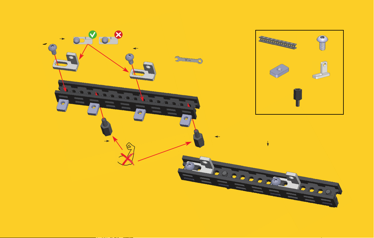
16
#1
#7
#5
Do not use much
force when tightening
Nylon Standoff s.
Use wrench for
Nylon Standoff s.
#1
1x Beam 90 mm 2x Bolt M3x6
4x Nut M3 6x10 2x L-Twisted Bracket
2x Nylon Standoff M3x8
# indicates number
of circular slot.
indicates counting
direction.
Page 16
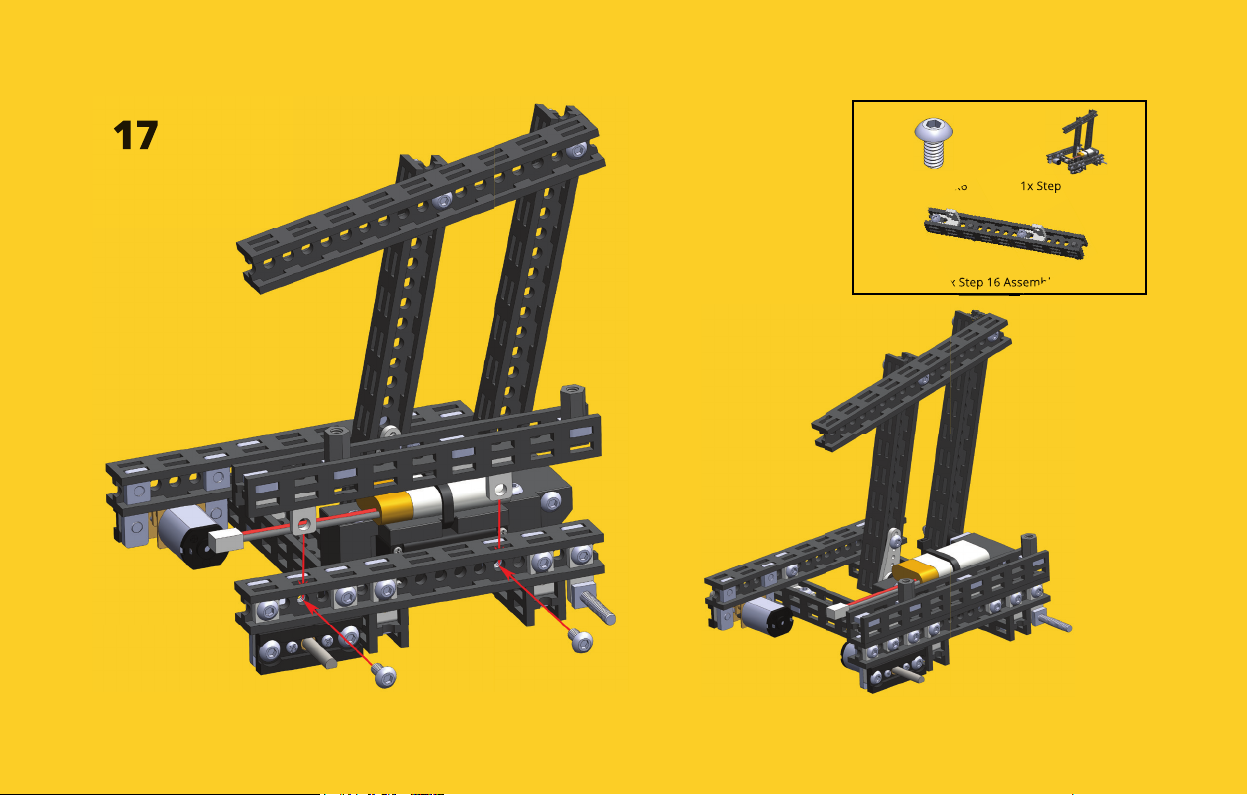
17
2x Bolt M3x6 1x Step 15 Assembly
1x Step 16 Assembly
Page 17
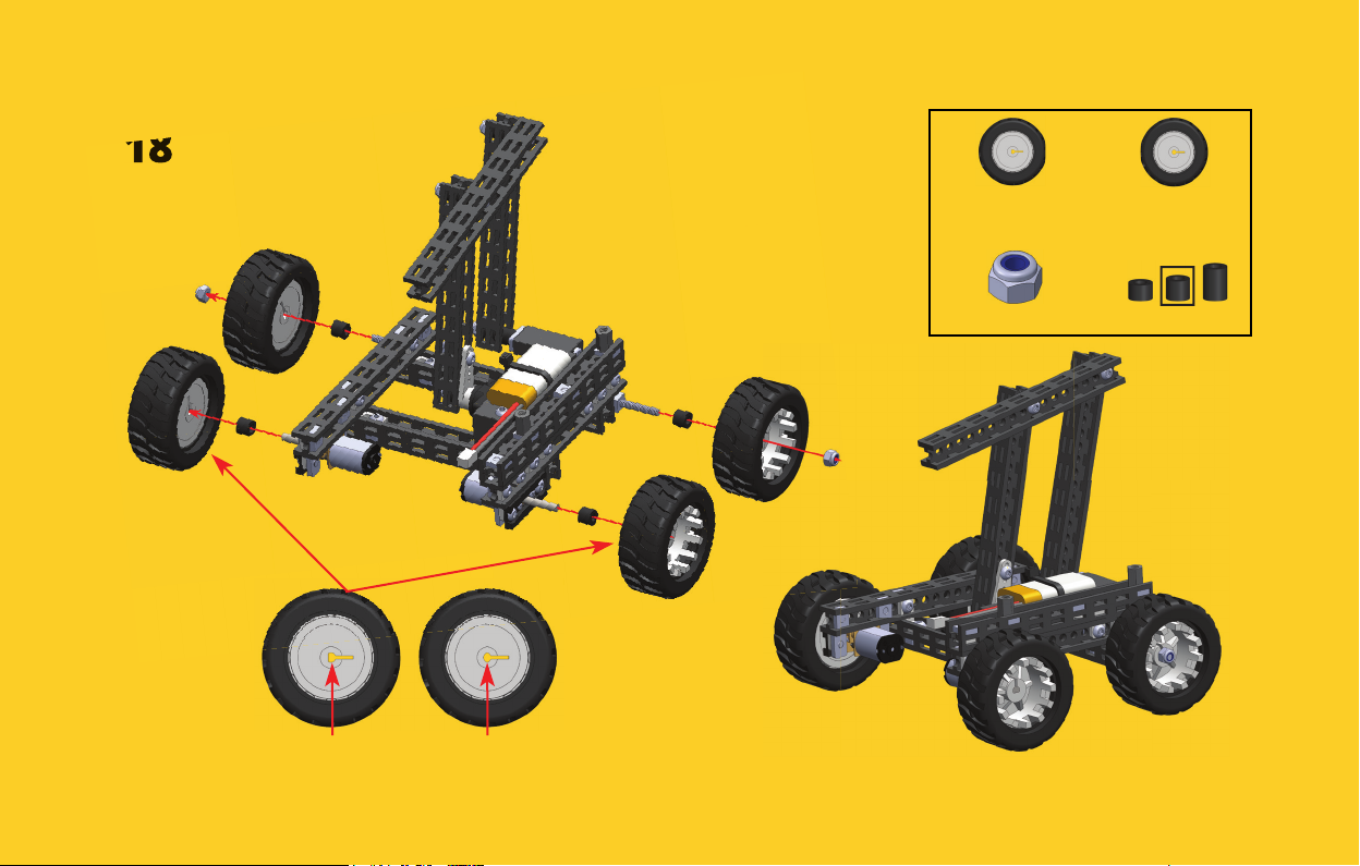
18
O-Shaft
D-Shaft O-Shaft
O-Shaft
2x 43 mm D-Shaft
Wheel
2x Lock Nut M3 4x Nylon Spacer 5 mm
2x 43 mm O-Shaft
Wheel
Page 18
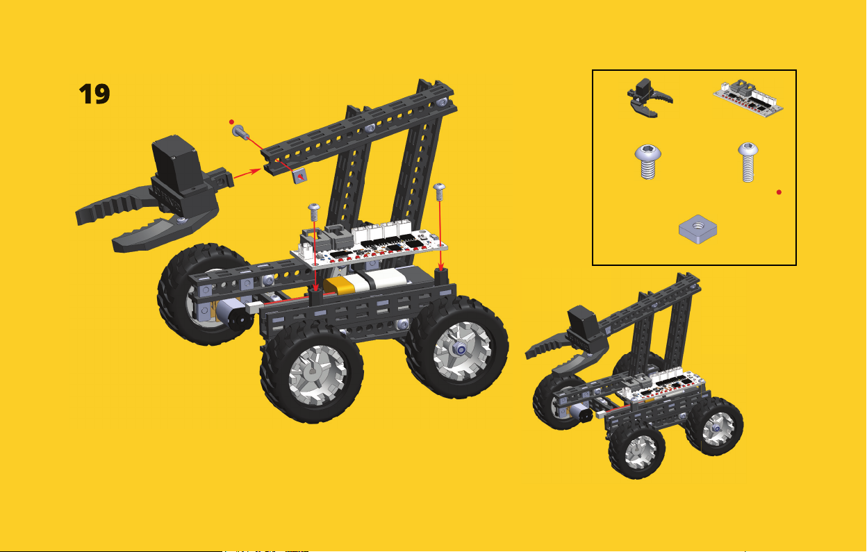
19
1x Micro Gripper 1x Mini Control Board
2x Bolt M3x6 1x Bolt M3x10
1x Nut M3 5.5x5.5
Page 19
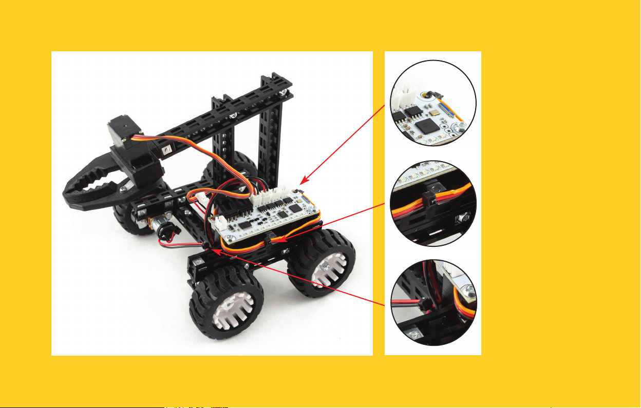
Tie wires with
Zip Ties so they
do not hang
messy and
Gripper part can
move freely.
Page 20
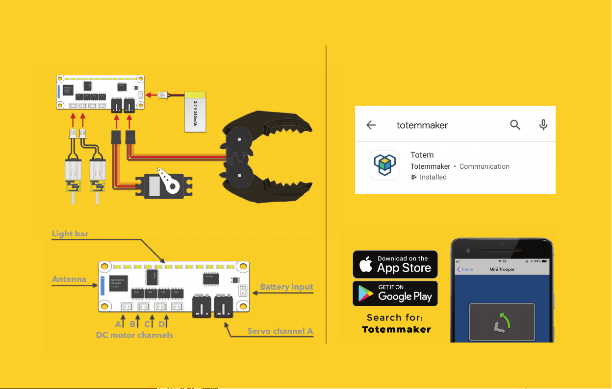
HOW TO CONTROL?CONNECTING ELECTRONICS
Download Totem app on your smartphone or
tablet via App Store or Google Play.
Follow the step by step guide to connect your
Gripper Bot to your device.
Page 21

TROUBLESHOOT
Can’t connect to the Mini Control Board with
Totem mobile application.
• Check if Mini Control Board is powered on (LEDs
should blink).
• Only one device can be connected to the board at
a time. Reconnect the battery to reset the board or
disconnect with another device.
• Check if your device is running the latest version of
Totem mobile application.
• Ensure that your device has Bluetooth functionality
and location service (GPS) enabled and Totem
mobile application has the location permission.
• Close Totem mobile application and run it again
(restart).
Servo motor doesn’t spin.
Servo motor connector may be plugged in upside down.
Flip it over.
LEDs are ashing when battery is not connected
and motors are spined manually.
This is a normal behaviour and doesn’t indicate any
malfunction.
None of the LEDs are ashing when battery is
connected.
Battery voltage is low. Charge the battery.
First LED of light bar is ashing when battery is
connected.
Battery voltage is low. Charge the battery.
DC motors are twitching or decelerates while
driving.
Battery voltage is low. Charge the battery.
DC motor spin direction is incorrect.
• Check instruction manual if motors are plugged to
appropriate DC motor sockets.
• Connect to Gripper Bot using Totem mobile
application. Go to “Settings” and switch “DC motor
pins” to “Inverted”. Write changes by clicking “Save”.
• A button conguration may be wrong. Reinstall
Totem mobile application in order to reset all the
settings.
Page 22

PRECAUTIONS:
ELECTRONICALLY OPERATED PRODUCT
Do not give this product to children aged 8 or below. As with all electronic products, precautions should be observed during handling and use to prevent electric
chock.
Adult supervision required.
Note to adults: to ensure that the child’s play is both safe and fun, please review all operating instructions and safety rules with your child.
SAFETY WARNINGS:
• Do not pick up vehicle while in motion.
• Keep fi ngers, hair, and loose clothing away from rotating wheels, to avoid the injury.
• Adult supervision is required when this vehicle is being operated.
• If you stopped operating the vehicle, remember to unplug the battery, to avoid accidental operation.
• If the vehicle is dirty, please clean it with dry and soft cloth. Do not clean electronics.
• Do not expose the vehicle to high temperature, high humidity, or direct sunlight.
• Indoor use only. Do not put this product in water to avoid damaging its electronic components.
• The product is made of complex electronic circuit and electronic components, do not disassemble, or modify the circuit board.
BATTERY SAFETY INFORMATION:
• This vehicle is designed to work with provided 250 mAh 3.7V LiPo battery and charger.
• Rechargeable battery must be charged by adult only.
• Do not leave charging without supervision of adult.
• There is a risk of fi re and personal injury if battery is punctured, damaged or misused.
• Do not disassemble or damage the battery pack.
• Use only the supplied 250 mAh 3.7V LiPo battery battery. Using any other battery may damage the model.
• Use only the included USB charging cable to charge the battery.
• Please check on a regular basis the wire, plug, battery, charger, and other electronic parts on the vehicle. If any damage is found, please stop using the
product immediately.
• Stop charging if battery becomes hot, smells, smokes or gives off strong odour.
• Never throw batteries into fi re to avoid explosion or leakage.
• Check the batteries on regular basis to avoid leakage.
• Recycle or dispose of batteries according to local laws and guidelines.
Page 23
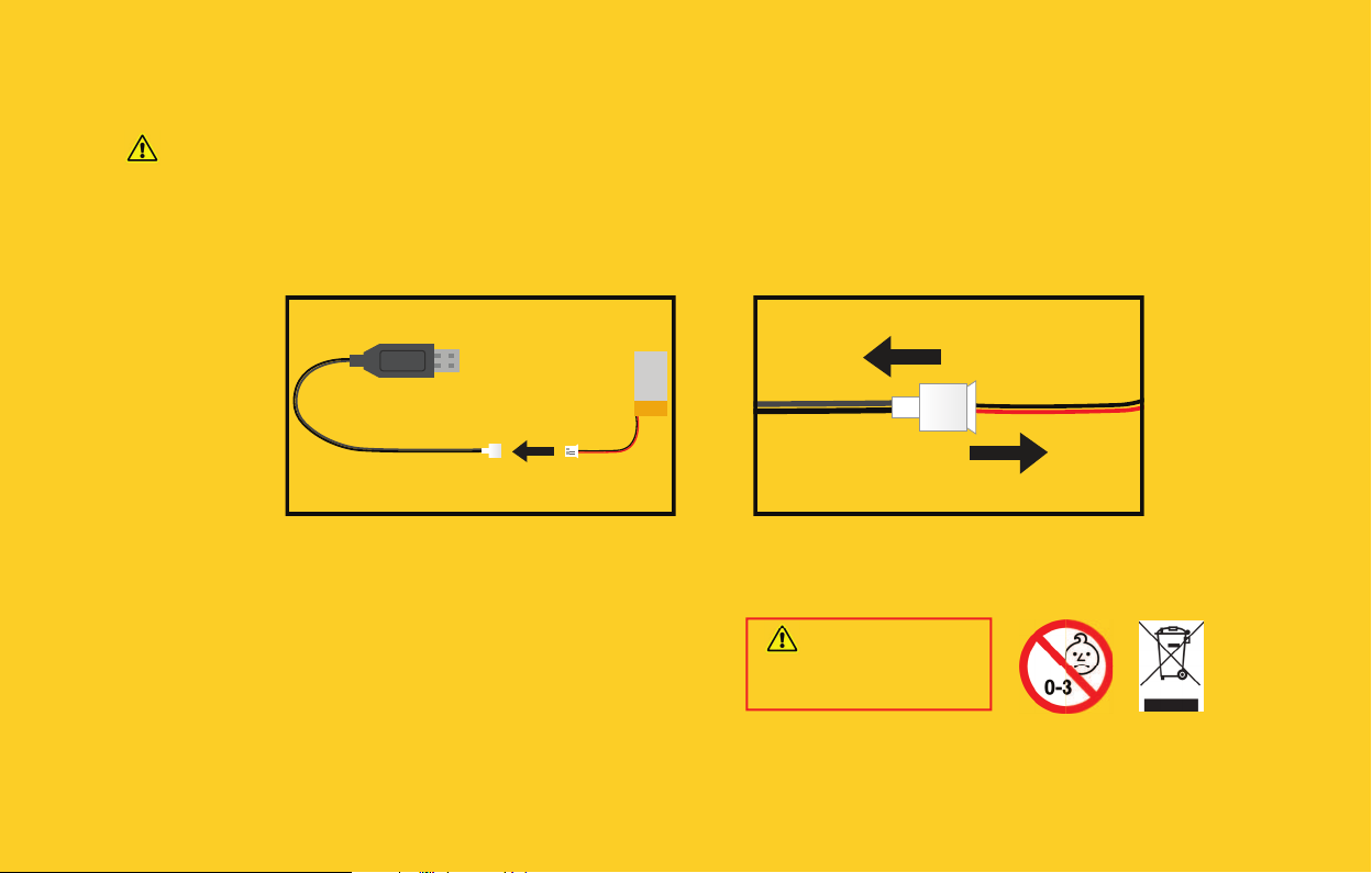
BATTERY CHARGING:
Rechargeable battery must be charged by adult only.
• The new battery pack needs to be charged before use.
• Connect the USB charging cable to 5V USB power source, such as laptop.
• Connect the battery to the charger (see picture 1). The charger will show a red LED light when charging the battery. When the battery is fully charged, the
red LED light turns off .
• To disconnect cables, hold the connectors of both cables and pull apart (see picture 2).
• Do not attempt to overcharge the battery.
3.7v 250 mAh
KEEP THIS INTRUCTION MANUAL AND THE PRODUCT BOX AS IT CONTAIN IMPORTANT INFORMATION FOR FUTURE REFERENCE.
Due to the continuous product improvement, the pictures on this manual may diff er slightly from the actual product. Please adhere to actual product instead.
Totem Maker names and logos are registered trademarks. All rights reserved.
www.totemmaker.net
Aldrea fi lalas Totem, UAB
Sauletekio al. 15-709, Vilnius, 10224, Lithuania
For customer support please contact: [email protected]
WARNING:
CHOKING HAZARD - Small parts.
Not for children under 3 years.
Page 24

 Loading...