

Page 1

03/2013
INSTALLATION
GUIDE
www.totemfire.com
CURVED and MULTISIDED
FIREPLACE
Very important: please read before fitting
a t o t a l v i e w o f f i r e
"CLASSIC" Range
Page 2

2
a t o t a l v i e w o f f i r e
Contents
1 Installation guide ................................................................................................................................... 3
1.1 Preamble ........................................................................................................................................ 3
1.2 Warning .......................................................................................................................................... 3
1.3 Chimney flue .................................................................................................................................. 4
1.3.1 General points ......................................................................................................................... 4
1.3.2 Dimensioning of the flue .......................................................................................................... 5
1.3.3 Layout of the flue ..................................................................................................................... 5
1.3.4 Chimney flue roof outlet ........................................................................................................... 6
1.3.5 Chimney flue floor duct ............................................................................................................ 7
1.3.6 Safety distance of the chimney flue ......................................................................................... 7
1.3.7 Covering flues ......................................................................................................................... 7
1.4 Type of walls around the fireplace .................................................................................................. 8
1.4.1 The mounting walls ................................................................................................................. 8
1.4.2 The floor .................................................................................................................................. 9
1.5 Outside air intake ........................................................................................................................... 9
1.5.1 Air intake outlet...................................................................................................................... 10
1.5.2 Air duct outlet on the fireplace side ........................................................................................ 11
1.6 Layout of the base ........................................................................................................................ 12
1.6.1 Fire hazard zone ................................................................................................................... 12
1.7 Fitting the base ............................................................................................................................. 13
1.8 Putting in place the fireplace ......................................................................................................... 15
1.8.1 Checks .................................................................................................................................. 15
1.8.2 Reflectors .............................................................................................................................. 15
1.9 Flue connector .............................................................................................................................. 16
1.10 Connecting the chimney flue to the flue connector ....................................................................... 17
1.11 The hood ...................................................................................................................................... 18
1.11.1 Convection grilles .................................................................................................................. 20
2 Initial checks in case of poor functioning .............................................................................................. 21
3 Summary of statutory texts .................................................................................................................. 22
4 Dimensions.......................................................................................................................................... 23
5 EC certifications .................................................................................................................................. 26
Page 3

3
a t o t a l v i e w o f f i r e
1 Installation guide
1.1 Preamble
We recommend that you read these instructions carefully before installing your appliance.
The TOTEM FIRE SAS company recommends that you entrust installation of its appliances to a qualified
professional.
1.2 Warning
These instructions concern TOTEM "Classic" appliances
TOTEM enclosed fireplaces comply with standard EN 13229
Characteristics of your Totem fireplace according to standard EN 13229:
Intermittent
Combustion on grate
Exclusively wood burning
Enclosed firebox
Firebox around which the brickwork will be assembled
A fireplace equipped with a TOTEM firebox must be fitted in compliance with all of the documents supplied
with the appliance. The instructions only apply to the construction of a fireplace equipped with a firebox
using firewood as a fuel, in a single family dwelling.
All local and national regulations, as well as European standards, must be observed when installing
and using the appliance.
IMPORTANT: Before installing the fireplace, it is necessary to first check its immediate environment,
notably whether or not:
- the characteristics of the chimney flue (shown on its information plate) are compatible with the
characteristics of the fireplace.
- the distance to combustible materials has been observed
- the characteristics of the materials making up the walls against which the fireplace is mounted
comply with regulations in force.
- the combustion air duct, measuring 200 cm², necessary for correct functioning of the appliance
exists, and is correctly proportioned.
- the mechanical strength of the floor is sufficient for the weight of the fireplace equipped with a
firebox.
Page 4
4
a t o t a l v i e w o f f i r e
1.3 Chimney flue
1.3.1 General points
Chimney flues must comply with the order of 22 October
1969, the order of 23 February 2009, county health
regulations and best practice relating to NF DTU 24.1 of
February 2006.
It must satisfy the conditions required by legislation in
force, in particular: impermeability, corrosion resistance
and thermal insulation.
- The installation can only be connected to a single flue.
The flue must be able to allow soot to be collected and must be able to be
chimney swept.
- The minimum cross-section shall be equivalent to that of the pipe of the
appliance.
The internal cross-section must be of the same diameter and shape over the
entire height of the chimney flue.
The chimney flue must protrude by a few centimetres into the room or area in which the fireplace is located.
.
Any chimney flue, cased chimney flue or lined chimney flue must include an information plate in fireresistant materials, put in place by the fitter.
This plate supplies the description of the structure and provides information about the characteristics of the
chimney flue.
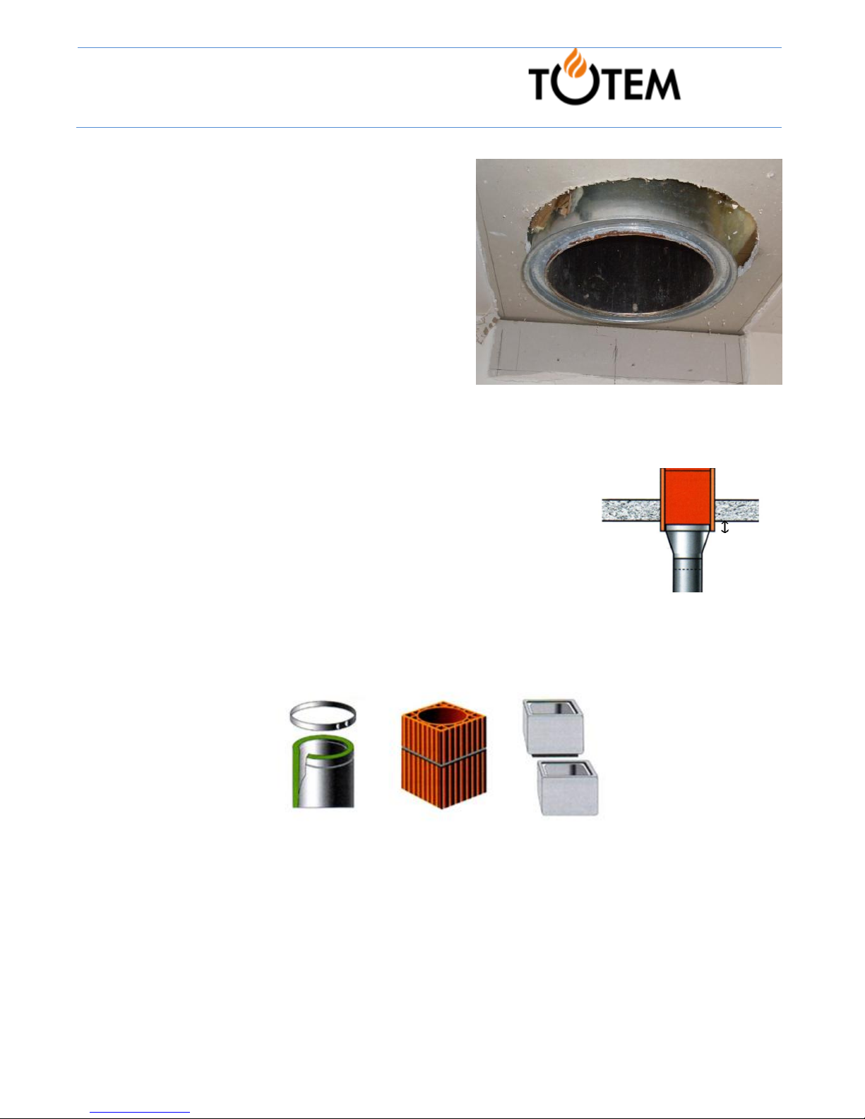
Chimney flue seen from below
metallic
terracotta
concrete
Page 5

5
a t o t a l v i e w o f f i r e
Example of description of components according to standard
EN 1856-1 relating to metal chimney flues.
EN 1856-1 T 450 N1 D Vm-L40045 G(xx)
EN 1856-1: Reference of the standard
T 450: Temperature class
N1: Pressure class
D: Condensate resistance class
Vm-L40045: Corrosion resistance class (durability) and Specification of the material of the inside wall (for
metal flues only)
G(xx): Chimney fire resistance and distance to combustible materials (xx in mm)
1.3.2 Dimensioning of the flue
Dimensioning of the chimney flue must be carried out in compliance with standard EN 13384-1, i.e. by
using:
- CSTB (Scientific and Technical Centre for Building) type graphs
- Poujoulat type calculation software
1.3.3 Layout of the flue
The flue must not include more than two bends, i.e. more than one non vertical section. Generally, the
angle of inclination is limited to 20°. However, if it is a smooth flue less than 5m in height, the angle can be
up to 45°.
If the flue exceeds 5m in length, the TOTEM FIRE SAS company recommends putting in place a draught
regulator. This device allows the draught to be controlled when it is too large. It must be accessible behind
a grille.
Page 6
6
a t o t a l v i e w o f f i r e
1.3.4 Chimney flue roof outlet
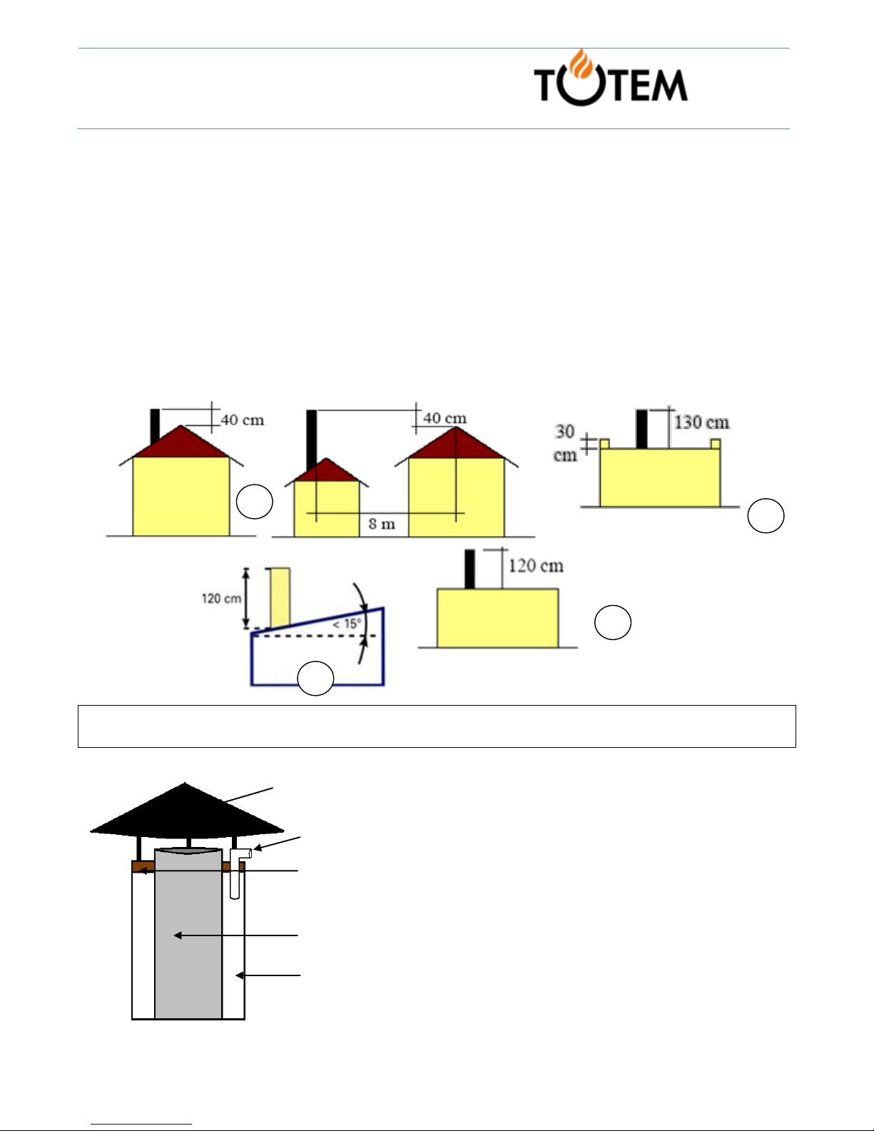
(1)The external orifices of collective, individual or natural draught flues must be located 0.4 metres above
any construction section less than 8 metres in distance.
(2)Within the scope of terrace roofs or slopes less than
15°, the orifices must be located at least 1.20m above the exit point.
(3) If the roof has acroterions higher than 0.2m, the orifices must be at least 1m from the top.
(4) If the acroterions measure less than 0.2m, the orifices must be located 1.20m from the exit point.
N.B.: the chimney flues are not designed to be used as anchor points for elements such as aerials, satellite
dishes or any other element the wind surface area of which would destabilize the flue.
Rain barrier
Leave a passage of air (used air inlet),
protected from the rain (5 cm²) in the
sealing to allow ventilation between the
lining and the chimney brick.
In the lower section, an orifice
measuring a minimum of 20 cm² must
be provided.
1 4 3
Chimney brick
Lining
Sealing (insulant + cement)
Flue used air inlet (cross-section
5 cm²)
With acroterion
exceeding 20cm
Flat terrace or acroterion not
exceeding 20 cm
Terrace roof or
slope < 15 °
2
Page 7
7
a t o t a l v i e w o f f i r e
1.3.5 Chimney flue floor duct
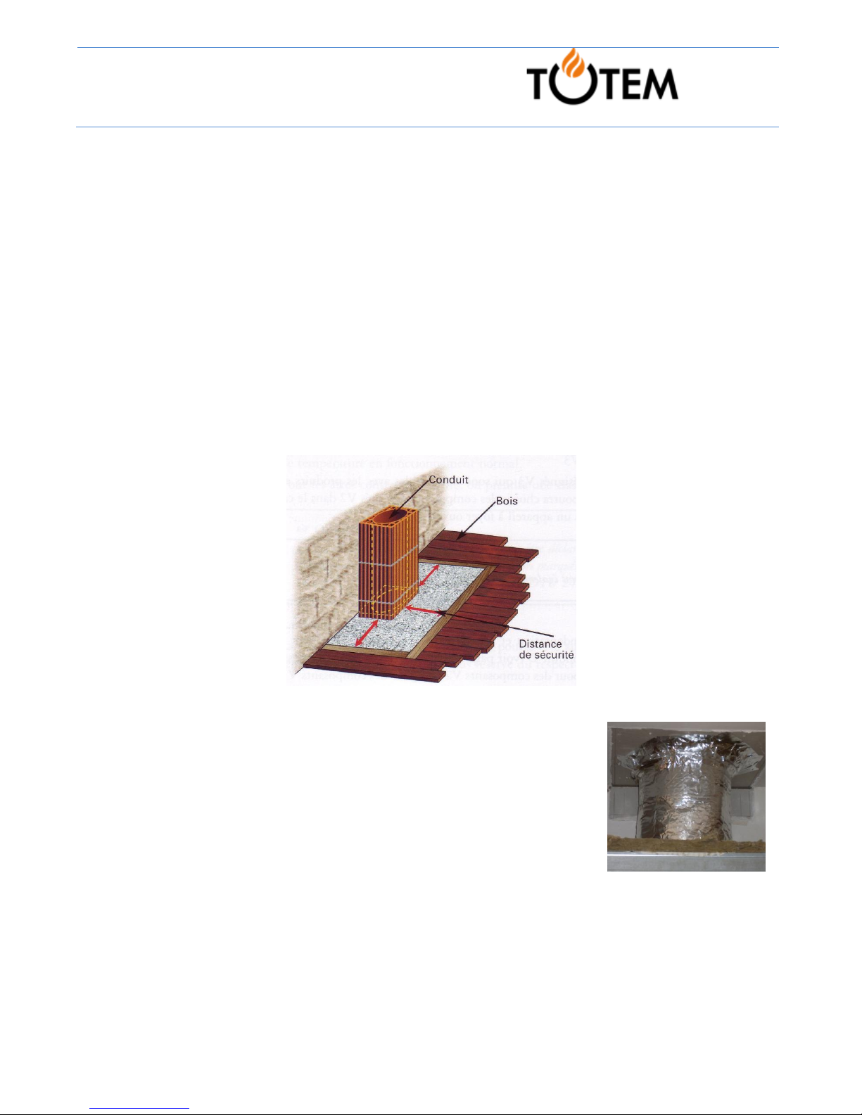
In the case of concrete floors, an opening must be provided when concreting for any floor ducts, leaving
around the flue sufficient space for putting in place a fire break plate.
No joint between the flue elements must be located in the thickness of the floor.
Wooden floor or false ceiling, it is advisable to use parts supplied by the flue manufacturer in order to
observe the associated precautions: stability, safety distance, thermal shock and free expansion of the flue.
The fitting of perforated safety distance plates is compulsory (case of a metal flue).
1.3.6 Safety distance of the chimney flue
The safety distances to be observed for the chimney flue are those of CSTB (Scientific and Technical
Centre for Building) graphs and DTU (Building Code) standards.
1.3.7 Covering flues
The temperature of the outside wall of the chimney flue must not exceed 50°C
(living areas) or 80°C (non living areas or inaccessible areas). If this is not the
case, the flue must be covered or concealed in casing or housing.
If the flue is insulated, ensure that you place the aluminium part of the insulant
against the flue. Secure with non-flammable adhesive foil tape.
1 2 3
1 – Flue
2- Wood
3- Safety distance
Covered flue
Page 8

8
a t o t a l v i e w o f f i r e
1.4 Type of walls around the fireplace
1.4.1 The mounting walls
The mounting wall must not include any combustible material and must be
strong enough to support any anchoring required by the structure.
If the mounting wall contains combustible materials or materials which may
degrade when subject to high temperatures, which cannot be removed, it is
advisable to create a non-combustible inner partition which is resistant to high
temperatures.
Insulation boards must be joined together using non-flammable aluminium foil
tape.
Check the levels and alignment of the mounting walls.
Aluminium adhesive tape
3 cm thick insulant +
aluminium foil
Page 9
9
a t o t a l v i e w o f f i r e
1.4.2 The floor
On a wooden floor, a joist filled with a concrete slab must be provided.
Assess the mechanical strength of the supporting floor according to the weight of the fireplace. The floor
must not warp.
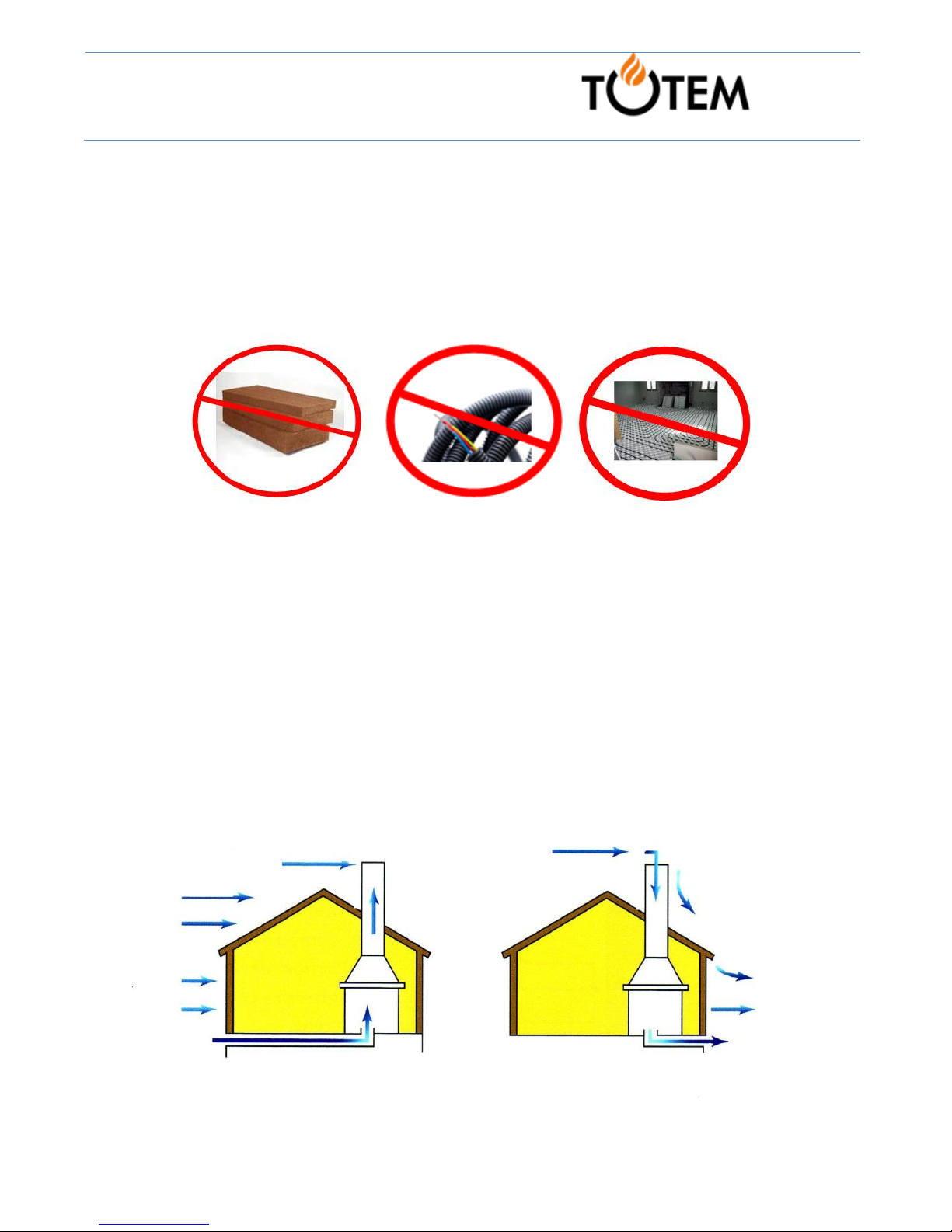
No installations such as water pipe or trunking, under-floor heating, compressible insulation, must be
inserted in the area taken up by the fireplace’s foundation.
1.5 Outside air intake
The functioning of a fireplace requires a supply of air additional to that required for air renewal in premises.
A special combustion air duct is therefore necessary.
The combustion air duct must be located directly on the outside or in a ventilated space on the outside.
The air inlet must be created on the side subject to prevailing wind. The actual air passage cross-section
must be 200 cm².
Note: This means that the meshing of the grilles which protect the air intake entrance generally restricts
50% of the air passage. It is necessary to use grilles with an exposed surface twice the actual desired
cross-section.
Prevailing winds
Prevailing winds
Fresh air
RECOMMANDED
NOT RECOMMANDED
Page 10
10
a t o t a l v i e w o f f i r e
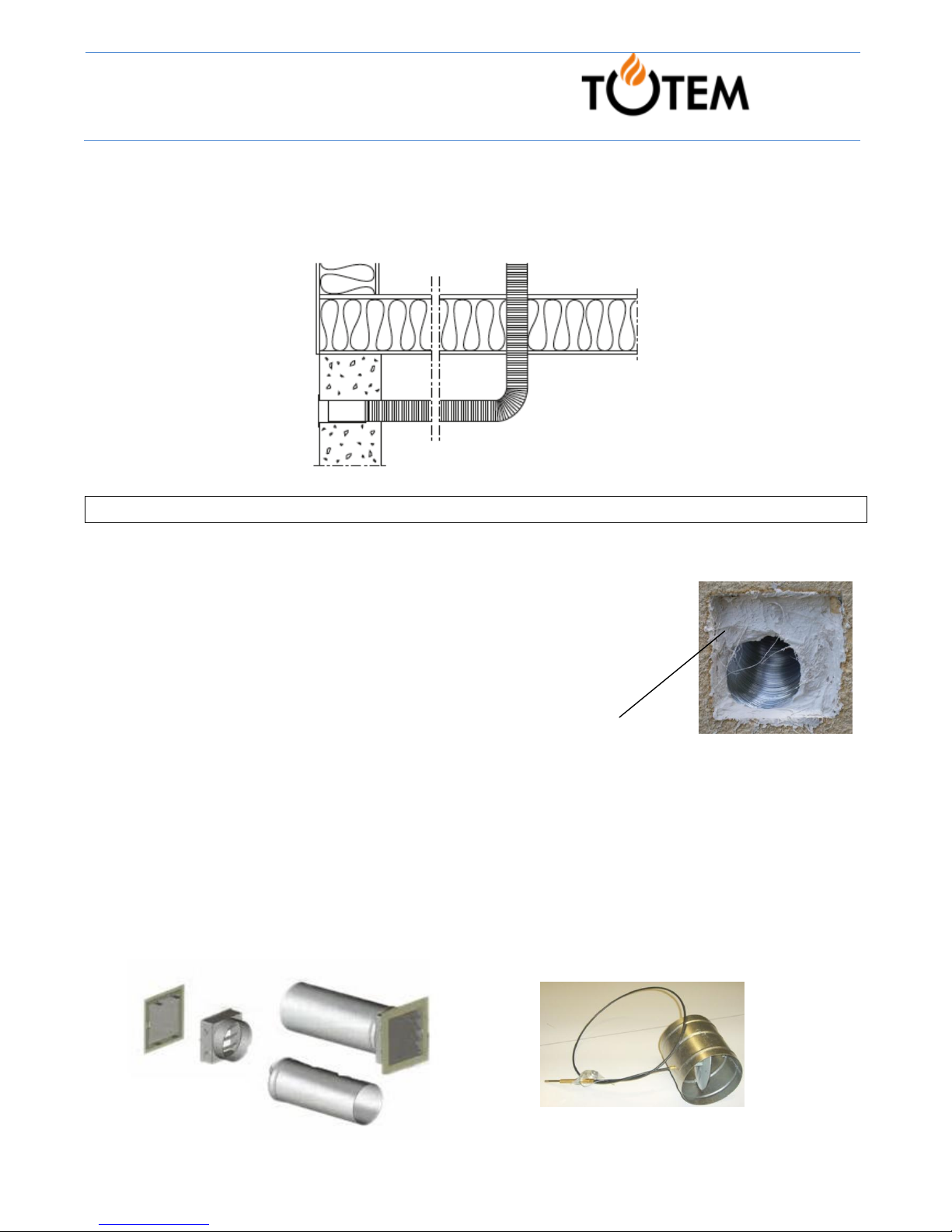
Air intake outlet
1.5.1 Air intake outlet
Air intake in the basement: In the case of air intake in the floor (in a room where the air is polluted), you
must fit a pipe which shall be directly connected to outside air
You must ensure that you do not use polluted air.
Passing through an outside wall: If the air duct passes through an outside wall
with internal cladding, it is necessary to fit an impermeable membrane to prevent
accumulation of dirt and dust in the wall/cladding wall space.
Any accumulation of dust or dirt can cause malfunctioning of the various mobile elements of the appliance
(e.g. smoke damper trap, outside air intake flap…)
It is necessary to install a grille which is easy to dismantle.Its meshing must be larger than 3mm.
The fireplace can be connected to the outside using a fresh air duct kit. TOTEM FIRE SAS recommends
that you systematically put in place a combustion air intake flap. This element must be placed upstream of
the adjustable air grate. It allows you to regulate the incoming air flow and to close the air inlets when the
appliance is not in use.
Sheath
Air inlet kit
Air intake flap
Page 11
11
a t o t a l v i e w o f f i r e
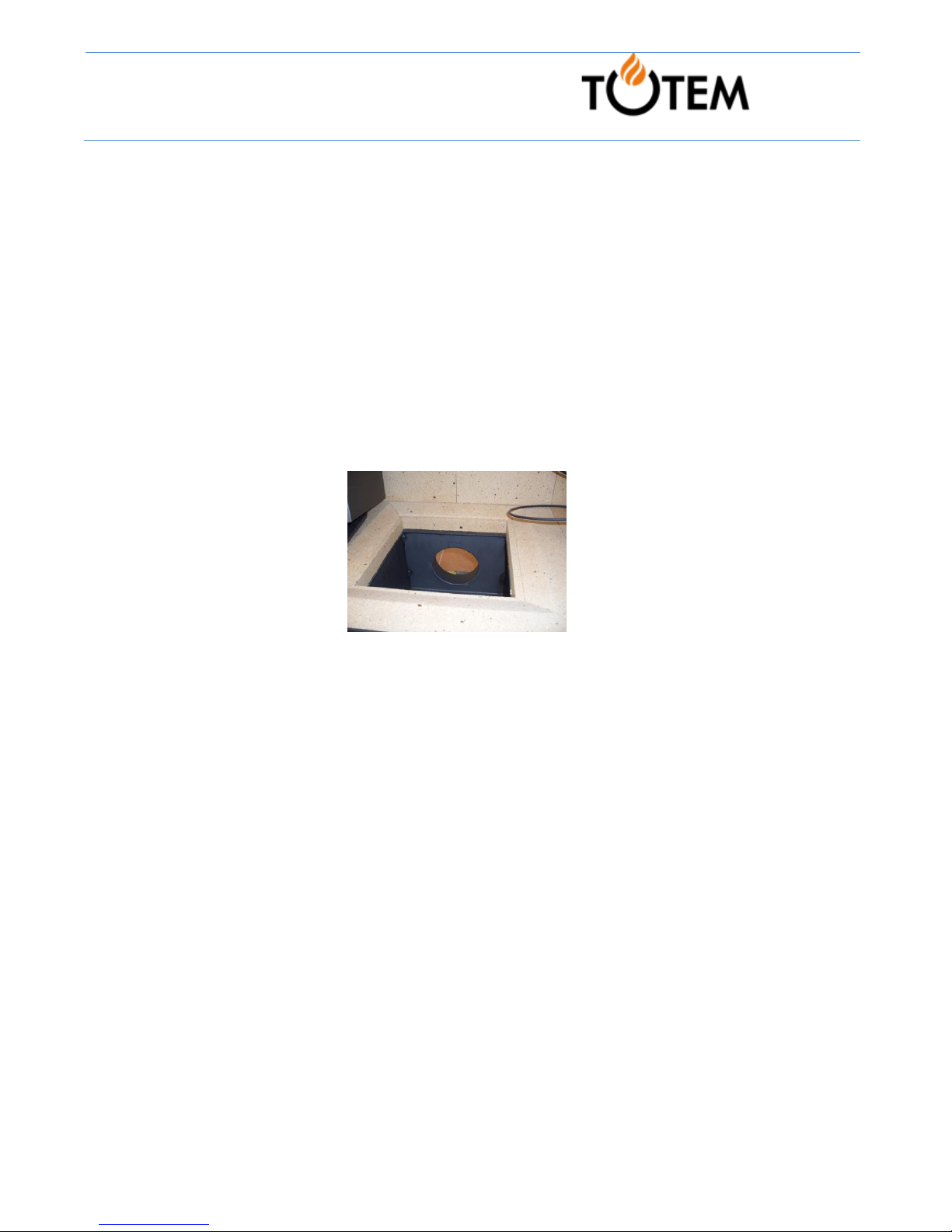
1.5.2 Air duct outlet on the fireplace side
It is located in the fireplace covering or as close as possible to it.
The air duct must not cause discomfort (draught) for the occupant when it opens directly into the room in
which the appliance is installed.
The appliance is fitted with an air intake system with several pre-cut seals allowing direct connection with
the outside.
The air duct must be directly linked to this air intake system. Only open one seal to carry out the
connection.
Seal
Page 12
12
a t o t a l v i e w o f f i r e
1.6 Layout of the base
Mark out on the floor the layout of the base, according to the chimney flue and the environment.
Dry install the first layer of the base, in order to check the layout and locate any perforations and cladding.
It is necessary to ensure that the necessary arrangements for the combustion air duct are respected.
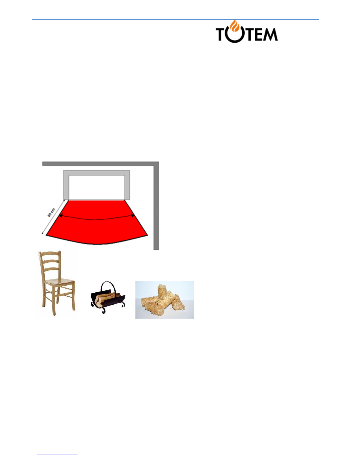
1.6.1 Fire hazard zone
Observe the fire hazard zone of the fireplace.
Do not install the fireplace too close to any flammable
objects.
Fire hazard zone
Page 13
13
a t o t a l v i e w o f f i r e
1.7 Fitting the base
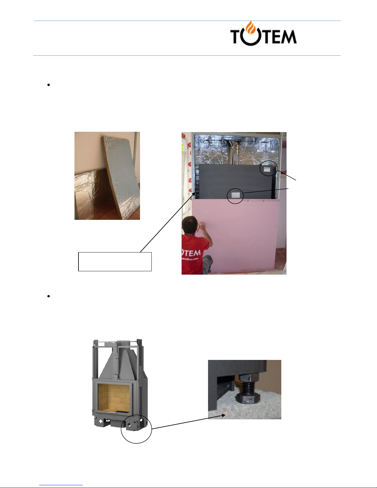
Brick the walls with fire-resistant materials.
Warning: Do not put any product containing silicone in contact with the fireplace painting.
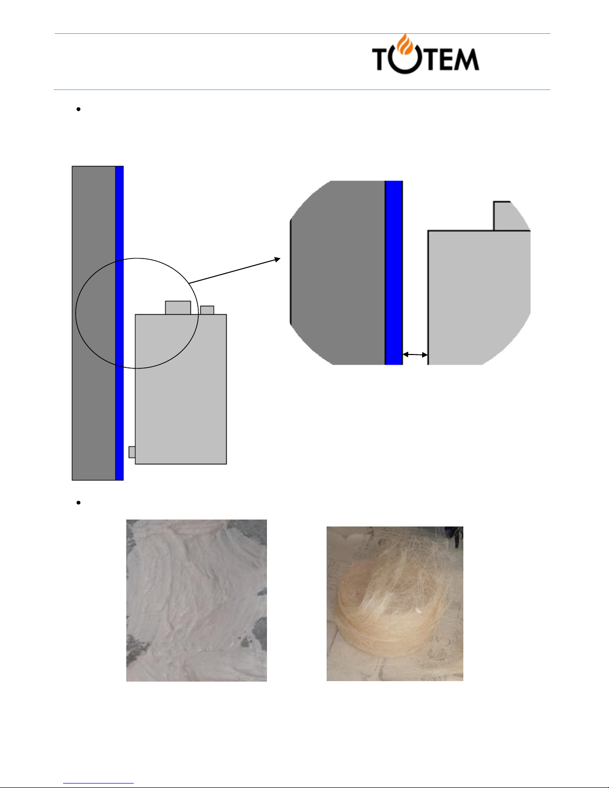
An air space (of at least 30 mm) must be provided between the appliance and the insulant of the covering.
3 cm thick insulant + aluminium foil
Regulate with the fireplace feet level adjustment screws.
Ensure that the fireplace is completely plumb to prevent any risk of warping to the body of the fireplace
when it heats up. Use cylinders designed by Totem to facilitate leveling of the appliance.
Air space ≥ 30 mm
Remove the
labels
Page 14
14
a t o t a l v i e w o f f i r e
Position the fireplace observing the safety distances. Leave an air space of at least 30 mm
between the insulant and the appliance.
Seal the base with plant fibres covered with casting plaster.
Wall + insulant
Appliance
30 mm air space
Page 15
15
a t o t a l v i e w o f f i r e
1.8 Putting in place the fireplace
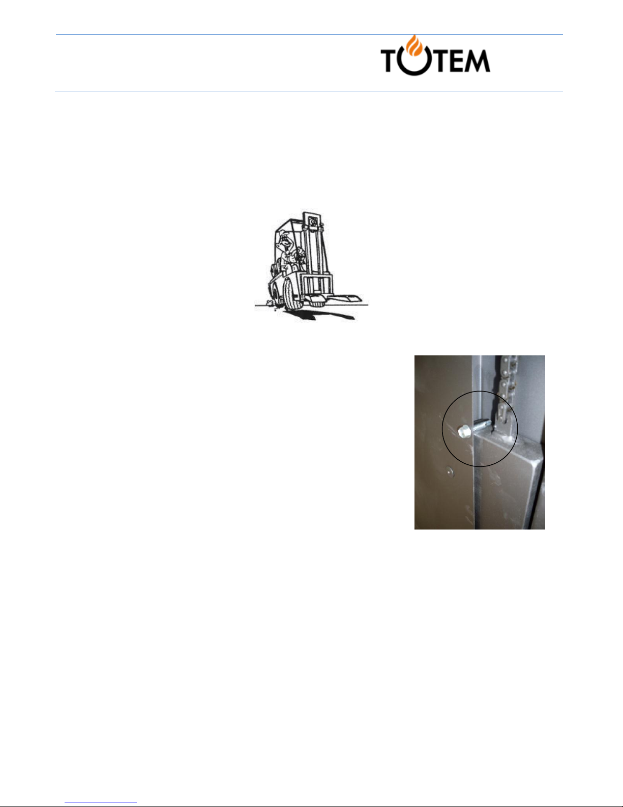
The various detachable elements (reflectors, heatproof materials…) must be removed from the appliance to
prevent mechanical shock with the glass when placing the fireplace on its support.
A suitable means of lifting is recommended.
1.8.1 Checks
Remove the door counterweight block.
Check that the door opening and lifting system function correctly.
Check that the various adjustment elements function correctly.
1.8.2 Reflectors
The TOTEM FIRE SAS company recommends that they are installed to improve efficiency.
The reflectors fitted on your fireplace reduce the temperature of the smoke evacuated and increase that of
the fire. In this way, they directly contribute to improving the performance of your equipment. They are
detachable for chimney sweeping.
Page 16
16
a t o t a l v i e w o f f i r e
1.9 Flue connector
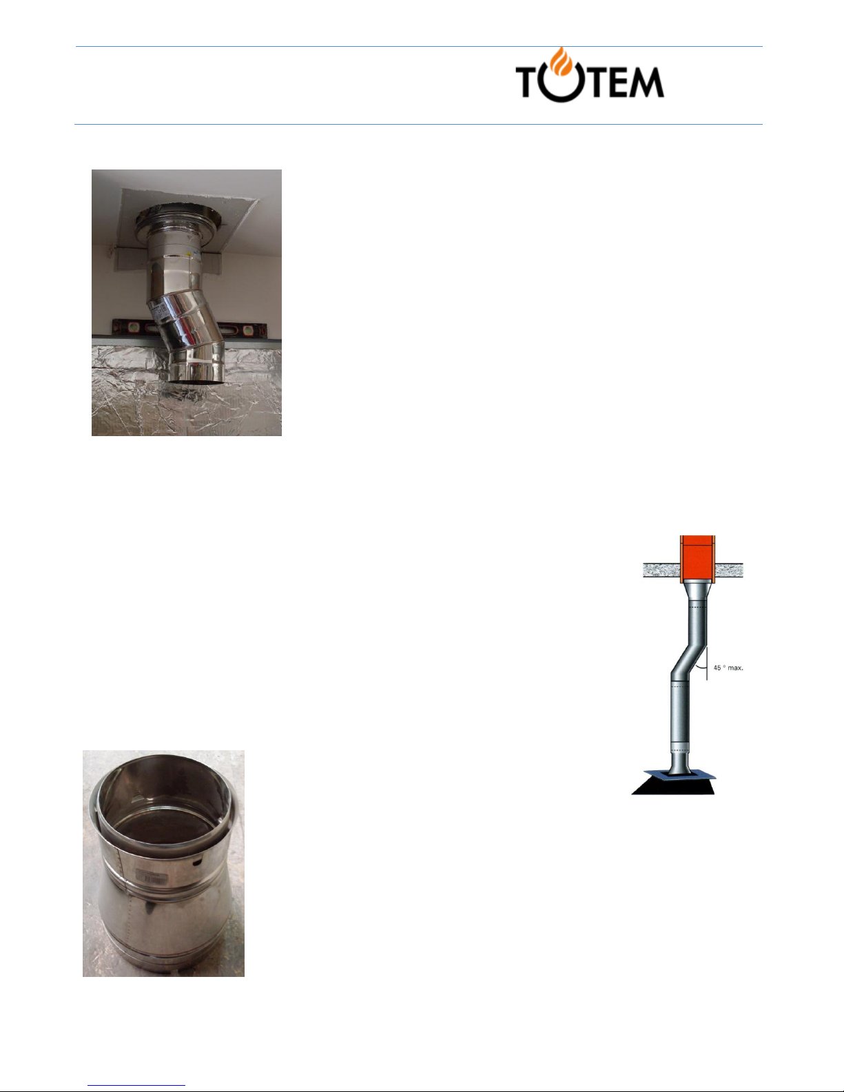
The appliance shall be connected to the chimney flue with standard metal
pipes.
The flue connector must not penetrate or cross any room other than the
one in which the appliance is installed.
Totem recommends a rigid connection. Totem does not recommend a
direct flexible connection.
Create a rigid section which abuts the damper metal plate then switch to a
flexible connection after installing a double lipped sleeve allowing
discharge of condensate.
The flue connector or any covering surrounding it must be accessible and
visible over its entire length either directly or by an inspection panel or
inspection grille.
Bending
The flue connector must include no more than two bends (not more than one nonvertical section).
The angles must be no more than 45° for smooth flues, otherwise 20°.
Junction of the flue connector on the appliance
The flue connector is connected by means of a double lipped sleeve (not
supplied) to the smoke damper trap of the appliance. In the case of a metal
flue, the junction between the elements cannot be created in the thickness of
the floor.
Double lipped sleeve
Page 17
17
a t o t a l v i e w o f f i r e
1.10 Connecting the chimney flue to the flue connector
Metal chimney flue
Connection to the insulated metal flue must be carried out using the fitting supplied by
the manufacturer of the insulated flue.
The socketing between the chimney flue and the flue connector must be at least
40mm.
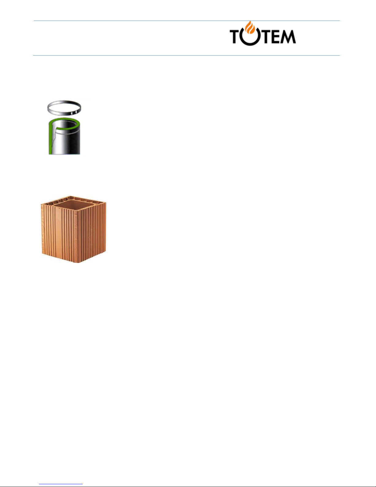
Chimney flue made from concrete or terracotta
In the case of a false ceiling, the flue must overshoot a chimney liner in the hood.
We recommend that you use the specially designed fitting to carry out the
connection.
Variation of cross-section
If there is a difference in cross-section between the chimney flue and the flue connector, the junction can
only be created via a shaped component, preventing a sudden variation in section.
The upper part of this reducer must be located:
- In the hood, less than 10cm under the hood’s false ceiling
Or
- In the space of the hood’s false ceiling
Or
- Less than 10 cm under the junction to the chimney flue if there is no hood false ceiling
Page 18
18
a t o t a l v i e w o f f i r e
1.11 The hood
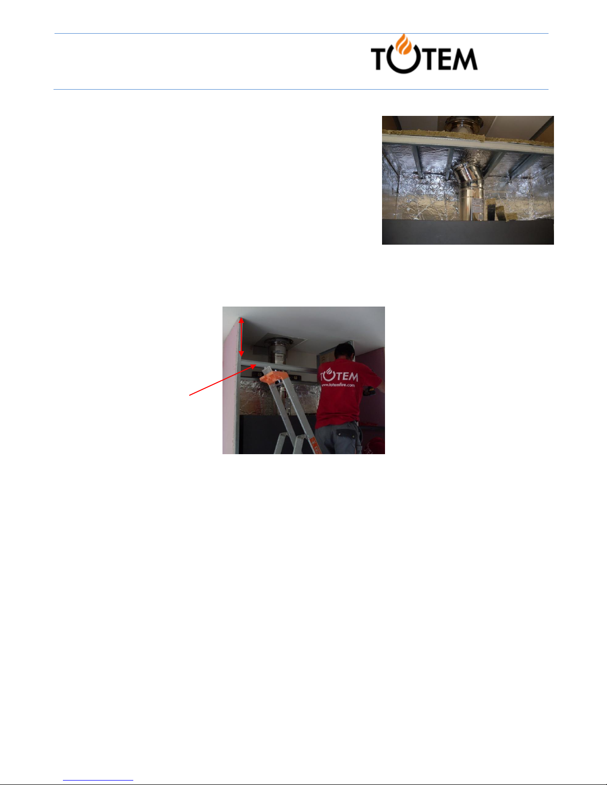
The hood, made from insulating materials, is made up of a heat
chamber topped by a box.
Any materials which are combustible or degraded by high
temperatures are removed from the walls in the area taken up by the
hood.
In the upper section, a false ceiling 30cm from the ceiling serves as a heat shield.
The inside surfaces of the gap between the false ceiling and the ceiling must be thermally insulated just as
the inside the hood. The creation of two lateral vents (one at the top and one at the bottom) allows this
space to be effectively ventilated.
30 cm
False
ceiling
Page 19
19
a t o t a l v i e w o f f i r e
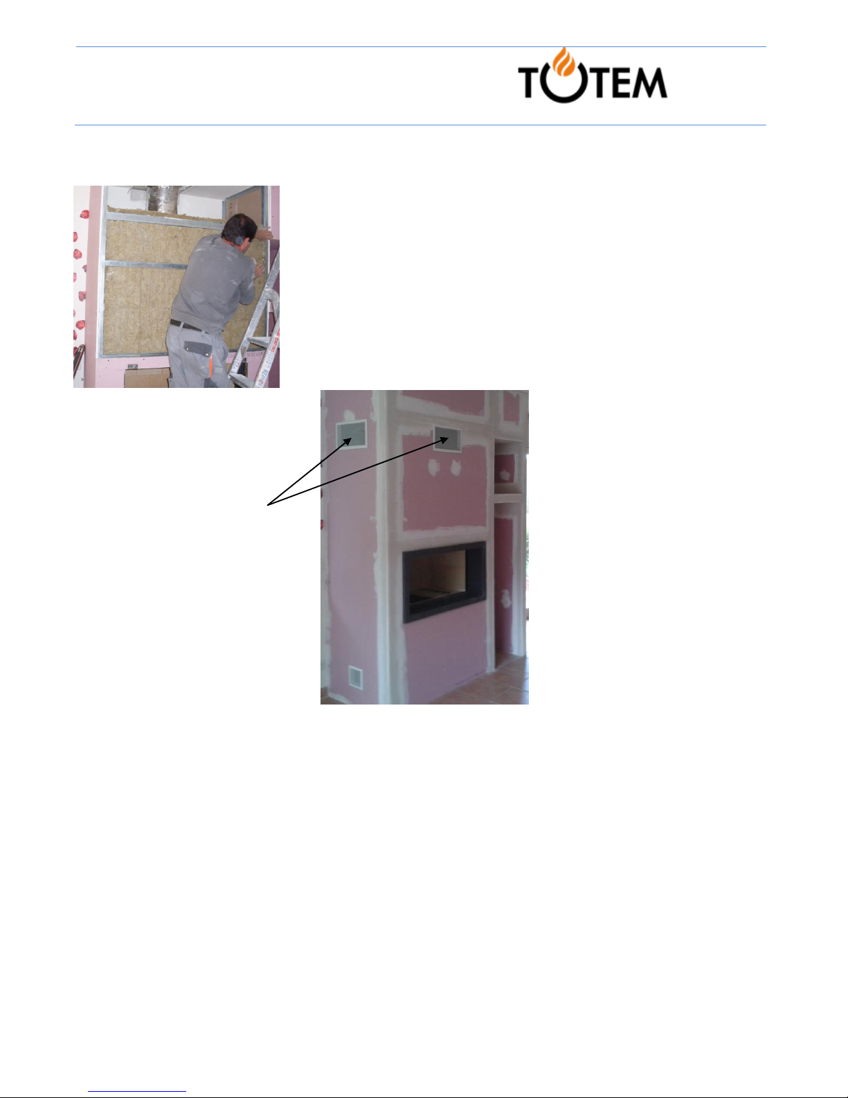
The inside surfaces subjected to the effect of radiation from the appliance
and the flue connector must be protected by insulating material.
No heat trap must be created inside the hood.
The inside of the hood must be visible from the hot air outlet or via an
inspection panel placed on the side of the hood.
This allows the flue connector to be checked and the inside of the hood to
be periodically cleaned.
In this way, accumulations of dust, which cause soiling of the ceiling and pollution of convection air, are
reduced.
Inspection grille
Page 20
20
a t o t a l v i e w o f f i r e
1.11.1 Convection grilles
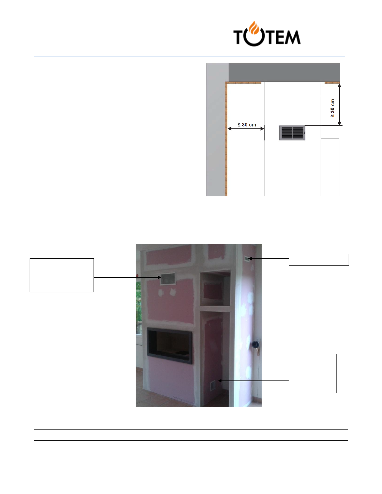
The convection grilles of the heat chamber, which are
compulsory, shall be fitted as high as possible but less
than 30cm from the ceiling (to be positioned at the level
of the false ceiling).
Concerning the parameters of the convection grilles:
Convection circuit:
- effective cross-section of the convection air inlets: 600
cm² minimum
- effective cross-section of the convection air outlets:
600 cm² minimum
N.B: It is possible to replace the ventilation grille by a slot with section equal or greater.
The air vents are to be installed above the false ceiling.
Note: The convection hot air outlet grilles must open into the room where the fireplace is located.
Air vent
Convection
air intlet grille
Convection air
outlet grille
The air vents allow
ventilation of the false
ceiling. They must be 20
cm² minimum each. They
must be staggered to allow
effective ventilation. One
close to the ceiling and the
other close to the false
ceiling.
Page 21

21
a t o t a l v i e w o f f i r e
2 Initial checks in case of poor functioning
When the door is closed, the wood burns too quickly and the fire is over active:
- Is the fire door shut properly?
- Is the smoke damper trap jammed?
- Are the reflectors in place?
- Do you use recommended firewood?
- Is the wood too small?
When the door is closed, the fireplace does not heat up sufficiently:
- Are the ventilation and convection grilles clogged up?
- Is the fireplace door correctly shut?
- Is the smoke damper trap obstructed?
- Have you loaded enough wood?
The wood does not burn well:
- Is the wood too humid?
- Are the pieces of wood too large? If so, saw them.
When the door is open, the draught of the fireplace is too weak, there is too much down
draught:
- Is the smoke damper trap obstructed?
- Are the combustion air flap (optional extra) and grille sufficiently open?
- Is the flue clogged up or poorly insulated?
- Does switching off the controlled mechanical ventilation facilitate the draught?
- Does removing the reflector improve the draught? If need be, reduce its length.
Page 22

22
a t o t a l v i e w o f f i r e
3 Summary of statutory texts
Legislative and technical texts:
- Building code standards 24.1 and 24.2
- European officially approved standards
- Technical evaluation document
- Technical application document
- CSTB (Scientific and Technical Centre for Building) book
- Order of 27 February 2009 concerning carbon monoxide emissions
Page 23
23
a t o t a l v i e w o f f i r e
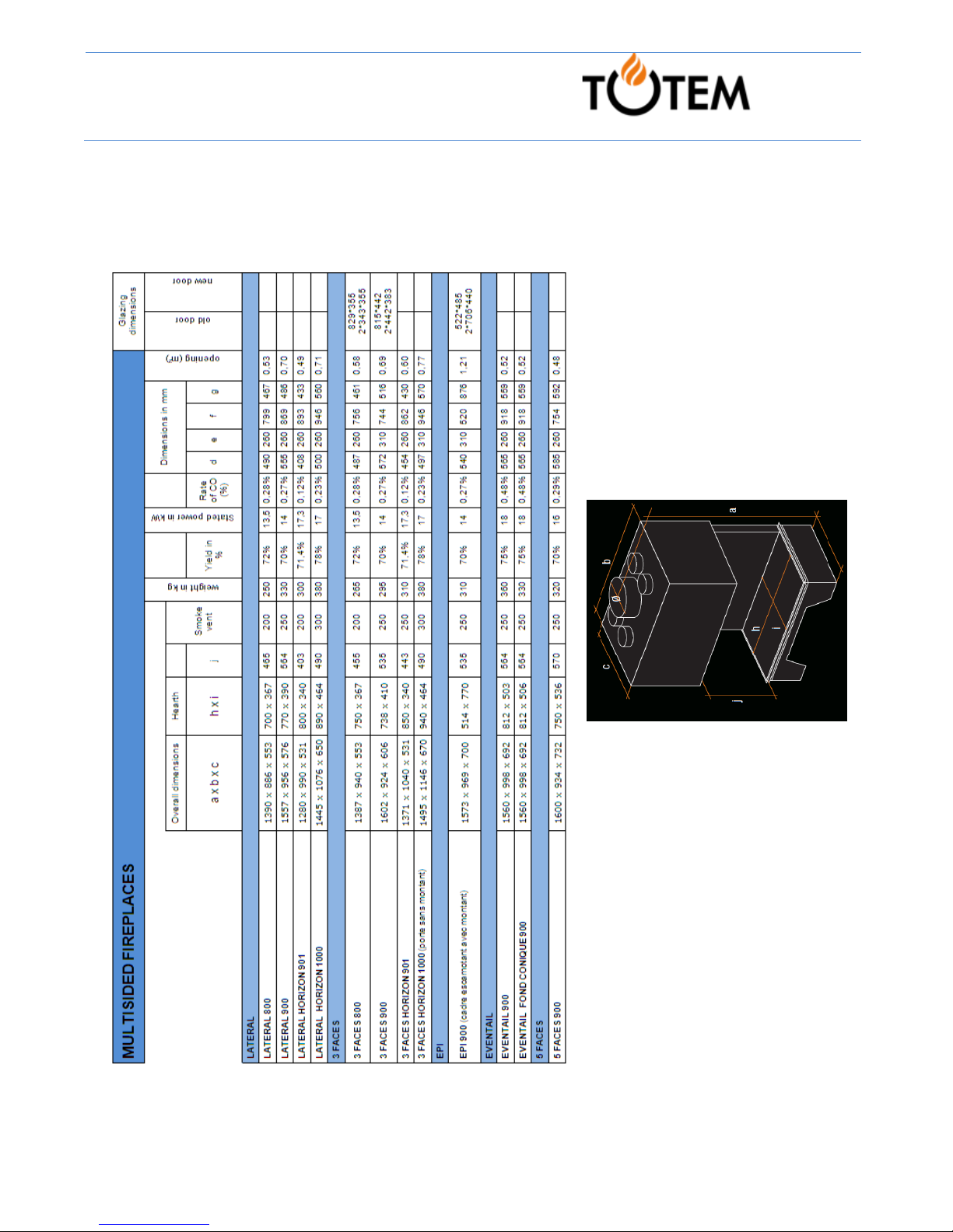
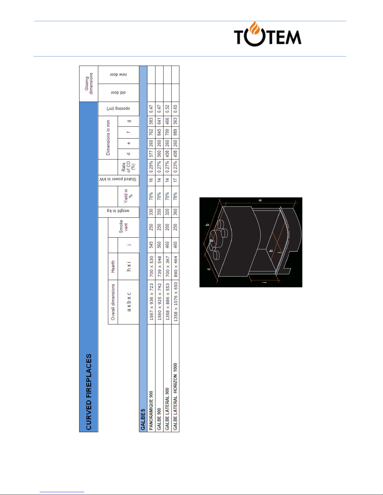
4 Dimensions
Page 24
24
a t o t a l v i e w o f f i r e
Page 25
25
a t o t a l v i e w o f f i r e
Reminder : If the flue exceeds 5m in length, the TOTEM FIRE SAS company recommends putting in place
a draught regulator. This device allows the draught to be controlled when it is too large. It must be
accessible behind a grille.
300 250 200 180
LATERAL 800 200
-
≥ 4 m ≥ 5 m > 11 m
LATERAL 900 250
-
≥ 4 m - -
LATERAL HORIZON 901 200
-
≥ 4 m ≥ 5 m > 9 m
LATERAL HORIZON 1000 300
-
≥ 4 m - -
3 FACES 800 200
-
≥ 4 m ≥ 6 m -
3 FACES 900 250
-
≥ 4 m - -
3 FACES HORIZON 901 250
-
≥ 4 m ≥ 8 m -
3 FACES HORIZON 1000 ( porte sans montant) 300
≥ 4 m ≥ 5 m - -
EPI 900 (cadre escamotant avec montant) 250
≥ 5 m - - -
EVENTAIL 900 250
-
≥ 4 m ≥ 5m > 11 m
EVENTAIL FOND CONIQUE 900 250
-
≥ 4 m ≥ 5m > 11 m
5 FACES 900 250
-
≥ 4 m ≥ 5m > 9 m
300 250 200 180
PANORAMIQUE 900 250
-
≥ 4 m ≥ 5 m > 9 m
GALBE 900 250
-
≥ 4 m ≥ 5 m > 9 m
GALBE LATERAL 900 200
≥ 4 m ≥ 5 m > 11 m
GALBE LATERAL HORIZON 1000 250
-
≥ 4 m ≥ 11m -
5 FACES
CURVED FIREPLACES
Smoke
vent
GALBES
Smoke
vent
Ø
Ø
MULTISIDED FIREPLACES
LATERAL
3 FACES
EPI
EVENTAIL
Page 26

26
a t o t a l v i e w o f f i r e
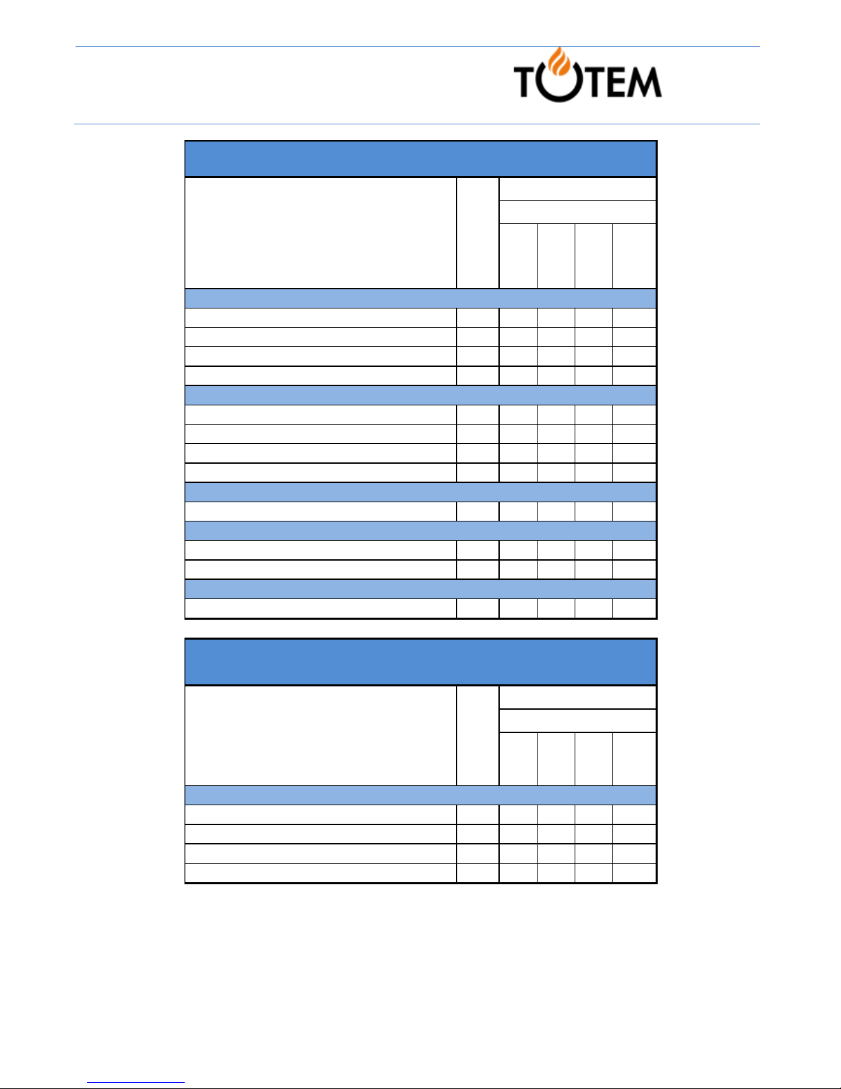
5 EC certifications
date number laboratory
LATERAL
LATERAL 800 03/11/2008 TD4089 CTIF
LATERAL 900 18/10/2005 TD3930 CTIF
LATERAL HORIZON 901 29/07/2010 TD4226 CTIF
LATERAL HORIZON 1000 04/11/2008 TD4088 CTIF
3 FACES
3 FACES 800 03/11/2008 TD4089 CTIF
3 FACES 900 18/10/2005 TD3930 CTIF
3 FACES HORIZON 901 29/07/2010 TD4226 CTIF
3 FACES HORIZON 1000 ( porte sans montant) 04/11/2008 TD4088 CTIF
EPI
EPI 900 (cadre escamotant avec montant) 18/10/2005 TD3930 CTIF
EVENTAIL
EVENTAIL 900 18/01/2006 1623BS005 CETIAT
EVENTAIL FOND CONIQUE 900 18/01/2006 1623BS005 CETIAT
5 FACES
5 FACES 900 12/02/2007 TD 3971 CTIF
date number laboratory
GALBES
PANORAMIQUE 900 12/02/2007 TD 3971 CTIF
GALBE 900 18/10/2005 TD3930 CTIF
GALBE LATERAL 900 18/10/2005 TD3930 CTIF
GALBE LATERAL HORIZON 1000 04/11/2008 TD4088 CTIF
CERTIFICATION CE : NF EN 13 229
MULTISIDED FIREPLACES
CERTIFICATION CE : NF EN 13 229
CURVED FIREPLACES
 Loading...