

Page 1
TOTEM ENERGY srl
via Ivrea, 70
10098 Rivoli (To) - Italia
+39 0119579211
User’s Guide
TOTEM 10A -TOTEM 20A MICROCOGENERATORS
Page 2

User’s Guide | TOTEM 10 - TOTEM 20
2 of 30
1. Declaration of Conformity .................................................................. 3
2. General Safety Instructions ................................................................ 4
A. Symbols Used in the Guide .................................................................. 4
B. Glossary of Terms and Definitions ........................................................ 4
C. Safety Instructions .............................................................................. 5
D. Potential Safety Risks .......................................................................... 7
3. Product Description ........................................................................... 9
A. General Information ............................................................................ 9
B. Product ID........................................................................................ 10
C. Module Main Components .................................................................. 10
D. TOTEM - Layout of Components ......................................................... 14
E. Safety Instructions ............................................................................ 15
F. Size and Overall Dimensions .............................................................. 17
G. Control Switchboard .......................................................................... 18
H. Connection Panel .............................................................................. 19
I. Noise Emissions and Vibrations .......................................................... 20
4. Use of the Micro Cogenerator .......................................................... 20
A. Preparing the Unit for Use ................................................................. 20
B. Operator Panel ................................................................................. 21
C. Starting and Working Principle ........................................................... 23
D. Operating Conditions ......................................................................... 24
E. Fuel Characteristics ........................................................................... 24
F. User System’s Water Characteristics ................................................... 25
G. Emergency Stop and Shutdown .......................................................... 26
H. Calendar .......................................................................................... 26
I. Diagnostics ....................................................................................... 26
5. Remote Control ............................................................................... 27
A. Local Area Network Connection .......................................................... 27
B. Remote Connection ........................................................................... 28
6. Maintenance ................................................................................... 29
Page 3
User’s Guide | TOTEM 10 - TOTEM 20
3 of 30
1.
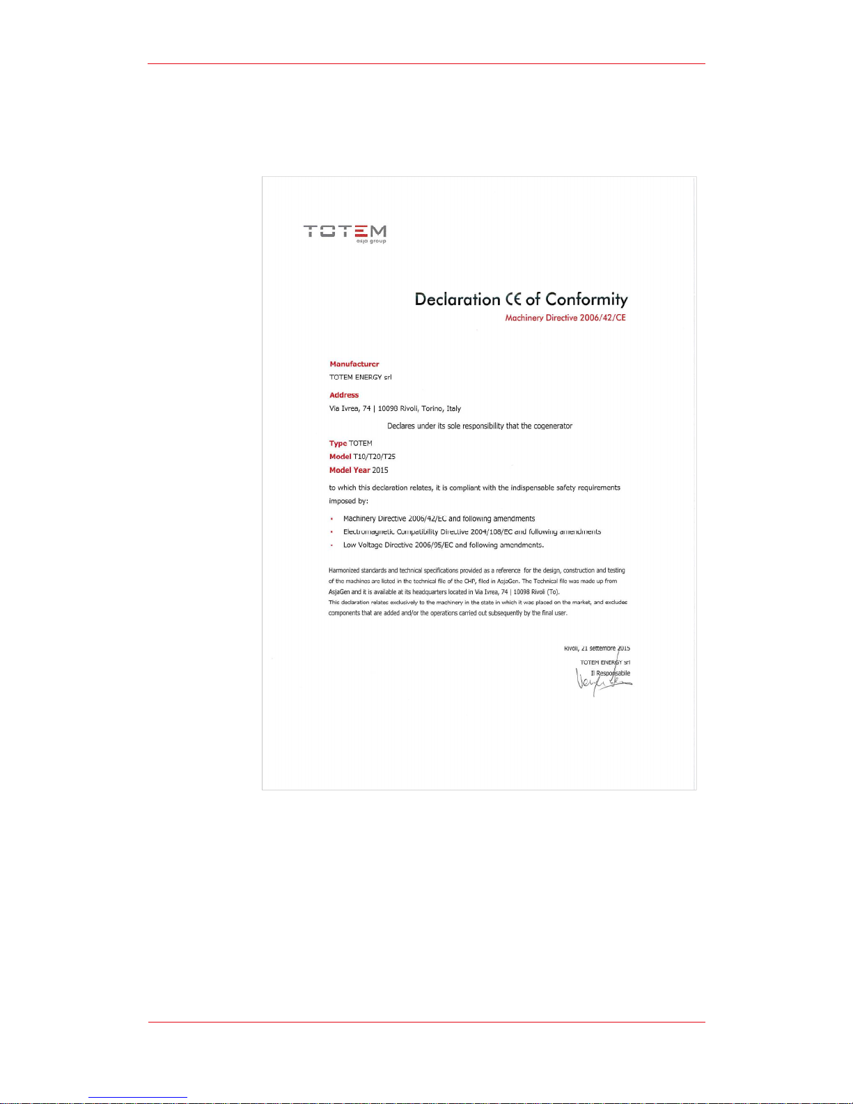
Declaration of Conformity
Page 4
2.
General Safety
A.
Symbols
B.
Glossary of Terms and Definitions
Machine Operator
specific skills
the operator’s control devices, checking on its proper functioning and reporting any
p
ossible anomaly to the Technical Support Service
Qualified
possessing specialist technical expertise in the fields of heating systems, hot water
production systems, electrical and electrical energy generating systems, combustible
gas-
fired plants and ap
engines as well as components thereof. Such professionals must be licensed as
required by the applicable laws in force in the place where the TOTEM® is installed.
Maintenance staff
possessing formally recognized professional skills, trained and authorized by Totem
Energy to carry out maintenance operations on the
Personal
Protective
shall mean the following safety wear and equipment:
PPE must be
starting and maintenance
User’s Guide | TOTEM 10
Instructions
Used in the Guide
: “Machine Operator” shall mean
any member of
who can only perform simple tasks, namely:
operating the unit by using
;
Technician: “Qualified Technician”
shall mean a trained professional
pliances equipped with Otto or Miller
: “Maintenance staff”
shall mean a Qualified Technician
TOTEM®
units
Equipment (PPE): “
personal protective equipment
hearing protections
(earmuffs or earplugs) for the hearing protection of
workers operating on the TOTEM® unit in operation with the sound
insulation panels removed (which
can be done solely for
troubleshooting or maintenance purposes).
protective gloves and goggles when working with battery acid, glycol
and engine lubricant oil;
safety shoes;
dielectric face shield and gloves when carrying out operations on
energized electrical parts.
worn by Maintenance staff at all times when
performing
activities on the TOTEM®.
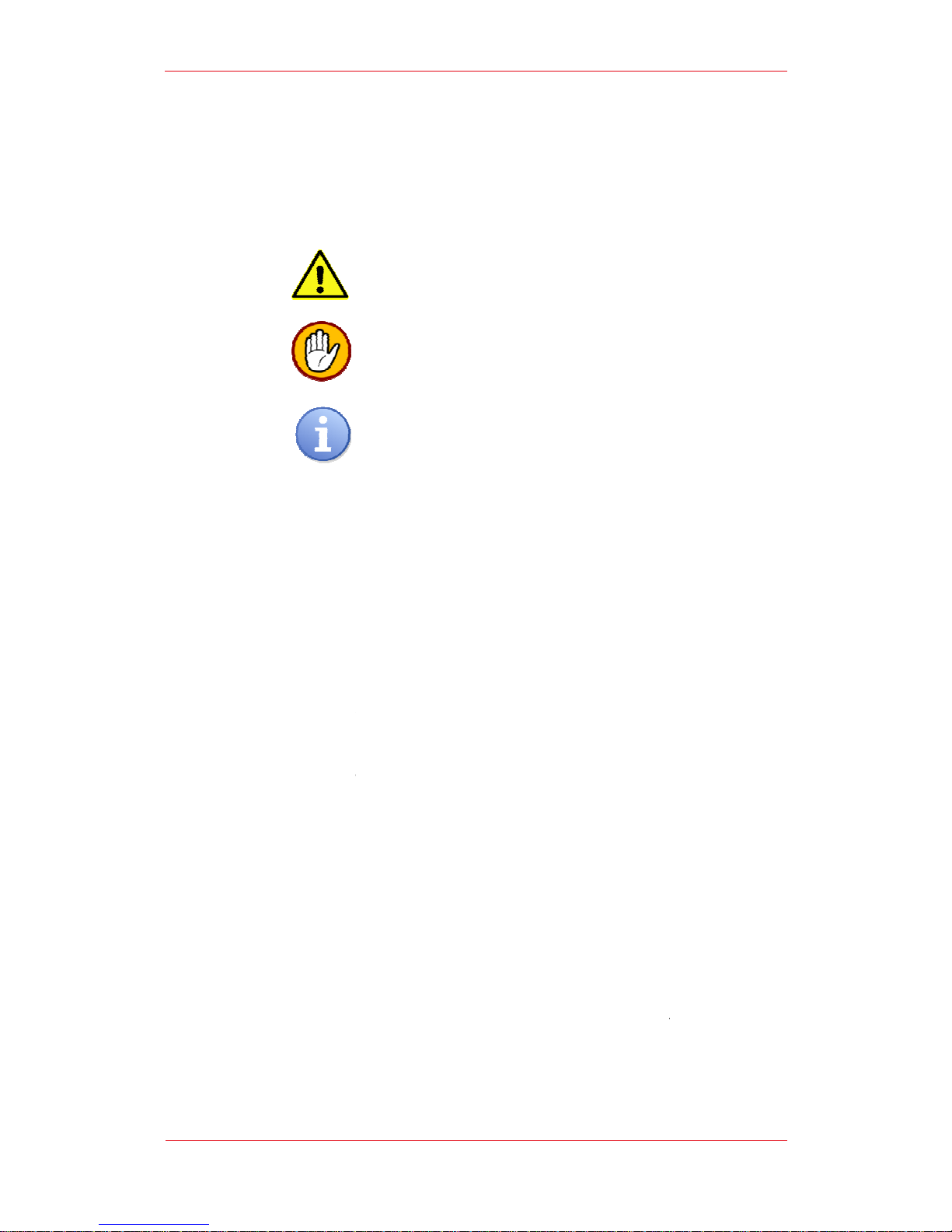
[Information]
This symbol indicates important information related to
the use of the equipment.
[Warning]
This symbol indicates operating procedures whose
incorrect
performance can seriously damage the equipment.
[Danger]
This symbol indicates operating procedures whose incorrect
performance can cause injury or even death.
- TOTEM 20
4 of 30
staff with no
-cycle endothermic
.
” (PPE)
installation,
Page 5

C.
Safety Instructions
If you smell gas odor:
If you smell products of combustion:
If you
Unit:
Installation, calibration and modification of the gas feed
performed by a Qualified Technician abiding by all applicable national and local
standards as well as by the instructions provided in this Guide.
Installation, calibration or
performed by a Qualified Technician abiding by all applicable national and local
standards as well as by the instructions provided in this Guide.
Installation, calibration or
by a Qualified Technician abiding by all applicable national and local standards
as well as by the instructions provided in this Guide.
It is mandatory to connect the exhaust gas evacuation line of the appliance to
an exhaust gas
requirements in force in the place where the TOTEM® unit is installed. Failure
to comply with said rule poses a serious risk to human and animal safety.
According to the provisions for use,
installed unit in good condition and to ensure the safe and reliable functioning
User’s Guide | TOTEM 10
turn your gas supply valve off;
ventilate the room;
do not operate any electrical device or appliance, including cell phones;
leave the premises and call a Qualified T
echnician or the gas utility
company immediately from a different location. If they are unavailable
or in case of an emergency, call the loc
al Fire Brigade;
if the room is equipped with a gas leak detection system, please report
any possible malfunctioning of said active safety equipment.
turn the appliance off;
ventilate the room;
call a Qualified Technician;
if the room is equipped with a smoke/carbon monoxide detection
system, please report any possible malfunctioning of said active safety
equipment.
see water, glycol, oil, or other
fluids’ spills on the floor or near
turn the unit off;
call a Qualified Technician;
shut off the User system’s circuits, if
any, e.g. water or gas supply
modification of the electrical system must be
modification of the water syst
em must be performed
evacuation duct built in compliance with all applicable legal
the user has an obligation to keep the
- TOTEM 20
5 of 30
the Totem
system must be
Page 6

of the micro cogenerator and o
relevant activities performed by Qualified Technicians.
The
user has an obligation to have the appliance maintained by a Qualified
Technician in accordance with the provisions of this Guide and ensuring
compliance with all applicable domestic and International standards.
TOTEM ENERGY
animals that may arise from incorrect installation or bad maintenance.
Before switching the unit on, always ensure that all protective panels and
guards have been properly mounted to avoid risks to the safety of personne
Do not obstruct,
Do not use or store any
flam
mable materials in the same room
installed.
When
installed.
The micro cogenerator, any
for its
detectors, pane
room etc.) must not be tampered with, modi
reason
may
damage, including
This booklet is an integral and fundamental part of the micro cogenerator and
it must be carefully kept by the user for future reference. In the event of a
change of ownership of the micro cogenerator or of the premises where it is
in
stalled, please ensure that this booklet is handed over to the new user.
This booklet contains up
issued, without prejudice to possible amendments or technical updates.
Since our products are const
pictures, process descriptions and technical data.
If you wish to request the most updated version of this document, to suggest
improvements or report any discrepancy, please contact the company.
This mi
designed for, namely, the combined production of:
User’s Guide | TOTEM 10
f all systems connected thereto, having the
shall not be held liable for
any damage to people, things or
not
even partially, the suction duct and exhaust pipe ends.
hazardous materials, such as
explosive, combustible or
where the micro cogenerator is
the unit
is in operation, do not stay in the room
auxiliary components
thereof, the systems
functioning (GAS, water, power, shut-
off devices, firefighting
ls, switchboards, components of the Totem Unit’s
fied or otherwise
whatsoever. Failure to comply with this provision
may cause injuries or
severely, people, animals or things.
-to-
date information referring to the date it has been
antly updated, slight differences may be found in
cro cogenerator must be used solely for the purpose it was expressly
hot water in domestic and/or industrial closed-
circuit water systems;
low voltage (400 V
olts) power for net metering, feed
self consumption.
- TOTEM 20
6 of 30
l.
where the unit is
needed
equipment,
equipment
altered for any
-in to the grid or
Page 7

TOTEM ENERGY
for any damages arising from the incorrect installation or use of the unit and, in
any case
instructions or with all applicable national and local laws.
D.
Potential
Risk
related to Mechanical
Injuries from mechanical
guards protecting the micro cogenerator’s moving parts
Said activities must,
specifically for said purpose and wearing the appropri
Risk related to Electrical Hazards
Electrical injuries can occur when safety devices are removed from the system,
the
control
Moreover, modifications of the existing
hazards if
performed by unauthorized
Said activities must,
specifically for said purpose and wearing the appropriate PPE.
Risk related to Thermal Hazards
During regular functi
high temperatures.
with frame panels properly mounted, thus preventing access to hot components.
Only
authorized
Risk related to Noise Hazards
In regular op
the frame’s heat
emissions.
Risk
related to Vibration Hazards
The TOTEM® unit is fitted with suitably sized anti
vibration transmission to the structures and installations connected thereto.
The removal
exhaust fumes line and the heating
Risk related to Electromagnetic Radiation/Waves Hazards
The TOTEM
to
electromagnetic
asynchronous generator can cause disturbances temporarily affecting the functioning
of electro-
medical
in close proximity to it.
Risk related to Contact with Hazardous Materials and Substances
On the inside, the TOTEM® module contains chemicals that are essential
proper functioning.
User’s Guide | TOTEM 10
shall bear no liability -
either contractual or extra
whatsoever
, from failure to comply with the manufacturer’s
Safety Risks
Hazards
hazards
can occur when the safety devices
-
are removed
therefore, be performed sole
ly by the Maintenance
ate PPE.
switchboard, or from the ignition system.
power supply system
personnel.
therefore, be performed solely by
Maintenance staff
oning, some of the TOTEM®’s inner components
The entire appliance must, therefore, work under safe conditions
Maintenance staff are authorized to remove the
unit’s panels.
eration, the whole TOTEM® unit
must work under safe conditions with
-insulation panels properly mount
ed, which lowers the Unit’s noise
-
vibration mounts to reduce
of anti-vibration fittings from connec
tions with the gas
system is strictly forbidden.
unit complies with Directive
2004/108/EC
compatibility. However, the electroma
gnetic fields from the
devices such as, for example,
pacemakers or hearing aids located
- TOTEM 20
7 of 30
-contractual –
- panels or
.
staff trained
from
may cause serious
trained
may reach
supply grid, the
relating
to its
Page 8

User’s Guide | TOTEM 10 - TOTEM 20
8 of 30
Namely, it contains substances such as battery acid, fresh/spent lube oil and glycolwater mixtures.
In the presence of spills outside the TOTEM® unit, any direct contact of these
substances with skin and eyes must be avoided at all times.
In the event that you come into contact with these chemicals, you must thoroughly
wash the affected body parts and seek medical advice if necessary, bringing the
relevant Product Safety Data Sheet with you. Said substances may even be hot and
cause skin burns.
When in operation, the TOTEM module also produces a constant flow of exhaust
fumes.
In the event of exhaust fumes build-up or leaks from the exhaust gas evacuation
system, leave the area immediately and switch off the module if possible.
Based on the standards in force in the TOTEM®’s place of installation, you may also
be required to install a CO/CH
4
gas detector in the module’s room.
The TOTEM already has an incorporated CH4 leak detector. Please contact our
Technical Support Service for the detector’s periodic calibration.
Risk related to Slip, Trip and Fall Hazards
Following breakdown or malfunctioning, lubricant oil, water-glycol fluids or battery
acid leaks may occur, making the floor slippery thus creating a risk for falls.
Said spills must be readily contained and whenever possible disposed of according to
the relevant laws in force.
Risk related to Emergency stop/Emergency shutdown
The TOTEM® module is designed to stop immediately following the activation of one
or more external safety devices connected to it.
Risk related to Power Supply Interruption
The TOTEM® is designed to enable an immediate safe stop function in the event of
an interruption of the mains power supply. A suitable interface protection device –
not supplied by TOTEM ENERGY - approved based on the applicable standards in the
module’s place of installation can implement the module’s disconnection from power
supply whenever the standards of applicable regulations are not met.
Risk related to Control Switchboard malfunction/failure
The TOTEM® module is designed to enable an immediate safe stop in case of
control switchboard malfunction or failure.
Risk from Breakdown during Regular Operation
If kept intact, used for the purpose it was designed for ensuring compliance with the
technical parameters set by TOTEM ENERGY as well as properly maintained, the
TOTEM® is designed to work under conditions that are fully safe for machine
operators and systems connected to it.
Hazards from Use in Environments at Risk of Fire/Explosion - EX
The TOTEM® is not intended for use in environments at risk of fire or explosion (Ex).
Do not keep or store materials that may increase the risk of explosion or fire in the
room where the TOTEM® is installed.
Page 9

User’s Guide | TOTEM 10 - TOTEM 20
9 of 30
3.
Product Description
A.
General Information
This User’s Guide is intended to provide the necessary information for the use of
TOTEM units. TOTEM micro cogeneration units are appliances that allow for the
combined production of electricity and heat at the user’s site, thus optimizing the use
of the fuel’s primary energy and reducing grid distribution and separate generation
losses.
CHP units, indeed, can be easily integrated into any technological environment,
enabling fulfillment of the heating requirements of different users in a variety of
sectors:
hospitality;
wellbeing;
catering;
health-care;
housing;
public;
agri-food;
distribution chains.
Using a micro cogeneration unit allows to achieve significant economic savings and
environmental benefits.
The unit consists of an endothermic engine originally devised for the automotive
industry, coupled to an asynchronous generator.
The heat produced in the endothermic engine’s combustion process is almost fully
recovered by means of a high-efficiency heat exchangers system and made available
to users as hot water.
Thanks to its modern propellers manufactured by FCA, specially engineered to run on
gas and optimized to work under steady-state, the unit allows for optimized
performance and longer maintenance intervals. Moreover, its modern Euro 6
technology enables a significant reduction of nitrogen oxides - NOx - and carbon
monoxide - CO - emissions as compared to conventional condensing boilers.
TOTEM® units’ compact size and versatility allows installation in tight equipment
rooms and their use on existing premises, including with environmental or
architectural constraints.
Its control systems allow to monitor and log data for power and heating load profiles,
including remotely. Moreover, it enables service staff to monitor any alarm signal
detected thus enabling emergency service in case of breakdown or malfunctioning.
Page 10
User’s Guide | TOTEM 10 - TOTEM 20
10 of 30
B.
Product ID
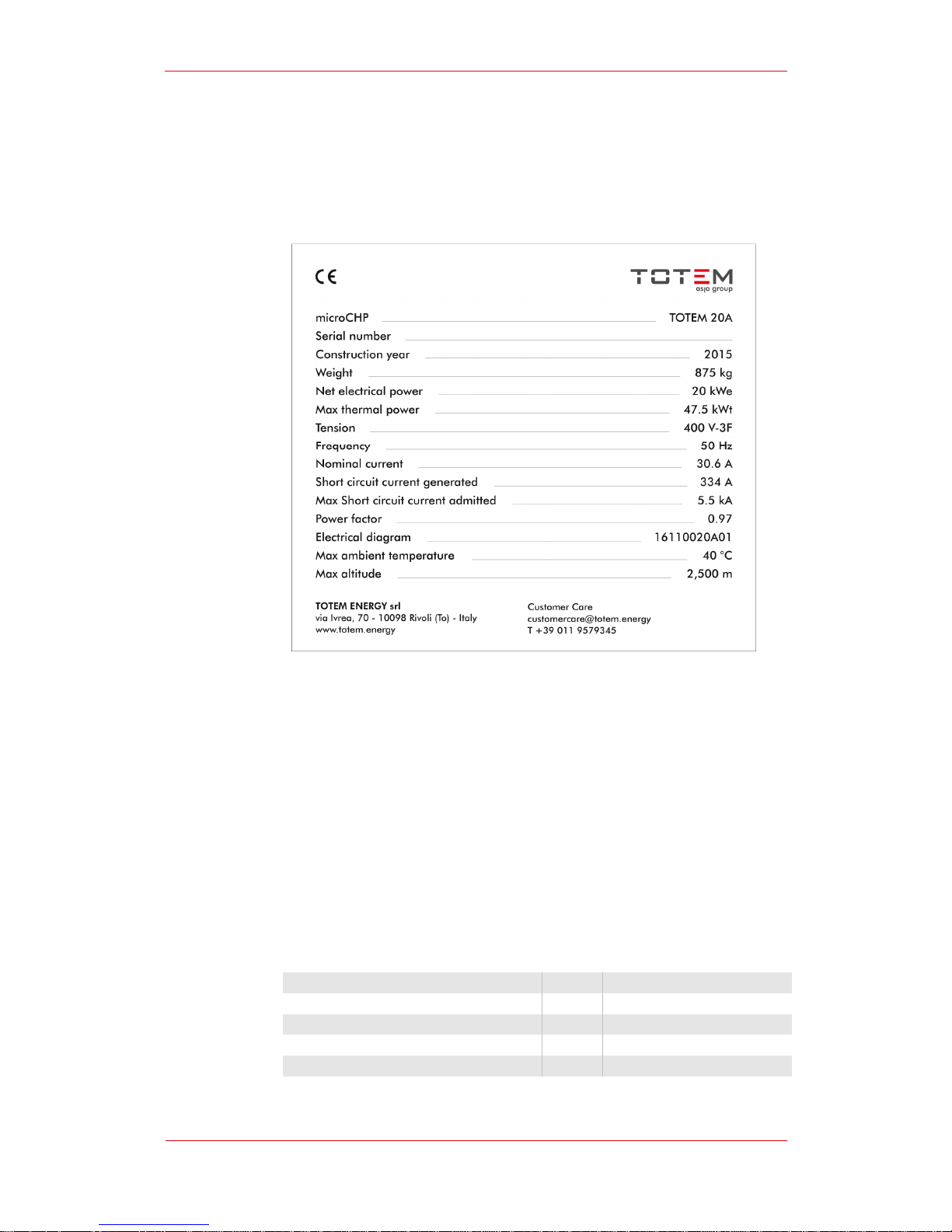
Each TOTEM® micro cogeneration unit is fitted with a special plate providing all
details for its identification.
C.
Module Main Components
Every TOTEM® module is the result of painstaking engineering research and
selected technological solutions combining high quality materials from specialist
suppliers. A detailed description of the module’s main components is provided in the
following sections.
- Endothermic Engine
FCA Fire 1.4 51 kW Bifuel Euro 6, four stroke, Otto cycle endothermic engine, fuel
feeding system fitted with a Venturi and throttle for fuel injection adjustment; fuel
injection is governed by a stepper motor.
Engine speed for the TOTEM® module 10 is set at 1,500 revs/minute.
Engine speed for the TOTEM® module 20 is set at 3,000 revs/minute.
Displacement cm3 1368
Maximum shaft power kW 51
Maximum Output Torque 104 Nm@3250 RPM
Arrangement / Number of Cylinders L-NA / 4
Vlaves per cylinder 2
Page 11

User’s Guide | TOTEM 10 - TOTEM 20
11 of 30
Compression ratio 11 : 1
Oil Pressure at 1,500 revs bar > 1.8
Oil Pressure at 3,000 revs bar > 3.5
Crankcase Cast Iron
Cylinder head Steel
Engine weight kg 88
- Asynchronous Generator
TOTEM 10 ASYNCHRONOUS GENERATOR - TECHNICAL FEATURES
Rated power kW 12
Electric power output kW 10
Pole number 4 - 1500 RPM
Rotor Squirrel cage
Cooling system Liquid
Type of cooling fluid water + glycol (max 30%)
Cooling circuit max pressure bar 3
Coolant max flow rate l/h 4000
Max pressure drop with max flow rate bar 0.5
Coolant temp. range °C 30 - 75
Hydraulic In/Out threading/coupling size inch 1"
Installation environment temp. range °C -20°C +60
Mechanical Design B3/B5 (foot and flange mounting)
Direction of axis horizontal
Terminal box position
On top, with cable exit holes on
the back
Effiiency 92.7 (Efficiency class: IE3)
Power supply - Voltage - Frequency Three-phase - 400V - 50 Hz
Insulation/Duty class H/S1 – continuous duty
Rated power factor >0.81
Winding connection Delta/Wye 400/690 V
Height of axis mm 160
Shaft diameter mm 42
Length mm 620 (shaft excluded)
Shaft length mm 110
TOTEM 20 ASYNCHRONOUS GENERATOR - TECHNICAL FEATURES
Rated power kW 22
Electric power output kW 20
Pole number 2 - 3000 RPM
Rotor
Squirrel cage
Brushless
Cooling system Liquid
Type of cooling fluid water + glycol (max 30%)
Cooling circuit max pressure bar 3
Page 12

User’s Guide | TOTEM 10 - TOTEM 20
12 of 30
Coolant max flow rate l/h 4000
Max pressure drop with max flow rate bar 0.5
Coolant temp. range °C 30 - 75
Hydraulic In/Out threading/coupling size Inch 1"
Installation environment temp. range °C -20°C +60
Mechanical Design B3/B5 (foot and flange mounting)
Direction of axis horizontal
Terminal box position
On top, with cable exit holes on
the back
Effiiency 92.7 (Efficiency class: IE3)
Power supply - Voltage - Frequency Three-phase- 400V - 50 Hz
Insulation/Duty class H/S1 – continuous duty
Rated power factor >0.81
Winding connection Delta/Wye 400/690 V
Height of axis mm 160
Shaft diameter mm 42
Length mm 620 (shaft excluded)
Shaft length mm 110
Compliance with standards:
2006/42/EC Machinery Directive;
2006/95/EC Low Voltage Directive;
2004/108/EC EMC Directive;
IEC EN 60034;
1997/23/EC Directive.
- Heat Recovery System
The TOTEM® unit is equipped with a high performance in-built heat exchange
system that can recover heat energy from the gen set, the engine water and oil
circuits, and exhaust fumes. The system does not include any heat dissipator device,
therefore, it is only activated following heat demand.
Heat is recovered by means of the following equipment:
Asynchronous generator: the heat recovery system is incorporated in
the gen set canopy. Please see the generator features section.
Engine Oil: AISI 316L stainless steel water/oil brazed plate heat
exchanger
Engine water: AISI 304 stainless steel brazed plate heat exchanger
Exhaust gases: AISI 304 stainless steel water/fumes tube bundle heat
exchanger.
The engine water circuit is governed by a high-efficiency circulator pump having the
following technical features:
Power supply V 230
Frequency Hz 50
Max. current A < 2
Page 13

User’s Guide | TOTEM 10 - TOTEM 20
13 of 30
Minimum inlet pressure 0.1 bar with fluid at 95°C
Fluid temperature °C -10 to + 95
Protection grade
IP X2D
Insulation class H
Equipment class I
The TOTEM’s internal circuit size, flow rates, temperature deltas and circuit pressure
values have been carefully calculated and set upon design.
- Exhaust Treatment and Discharge Line
Exhaust gases from the endothermic engine are conveyed along the treatment and
cooling line before being expelled. The exhaust discharge line comprises a 4-1
manifold, a coaxial exchanger, a three-way catalyst, a tube bundle exchanger for
heat recovery and an in-built silencer.
The 4-1 manifold conveys exhaust gases from the 4 engine cylinders into the
exhaust duct. It is equipped with a lambda sensor for injected mass control as well
as with a sensor checking gas temperature right at the engine outlet.
The manifold is efficiently insulated so as to minimize heat dispersion along this
section. Gases then go through the coaxial heat exchanger where a first cooling
stage takes place, after which they are sent to the three-way catalyst where
emissions are lowered. The ceramic substrate catalyst simultaneously reduces CO,
NOx and HC emissions. It is fitted with a sensor at the inlet to check the right
operating temperature for the catalyst, plus a lambda sensor downstream for a
second level titration control. The catalyst is thermally insulated, too. The gases
leaving the catalyst reach the tube bundle exchanger where they are cooled down
until condensation occurs (T<70°C).
Before being discharged, gases go through an exhaust gas silencer, specifically
devised to lower the noise emissions from the micro-cogenerator for the given rev
number.
- Electrical and Control Switchboard
The Electrical Switchboard complies with current applicable standards and it contains
all the electrical safety devices as well as all control devices governing the unit’s
functioning.
The TOTEM is governed by 3 control units:
ECU (Engine Control Unit): manufactured by Magneti Marelli, it governs
control of the endothermic engine. The control unit is set to work under
steady state conditions and it interfaces through CANbus system with
the MCU. It is located inside the unit’s enclosure;
MCU (Machine Control Unit) “Arya”: developed to fit specific TOTEM
ENERGY requirements, it governs the control and operation of the
TOTEM® unit through an interface with the ECU via CANbus and with
the Gateway via Modbus protocol. Also, it is connected to a multifunction multimeter that conforms to a 0.5s accuracy class in
compliance with IEC 62053-22 standards. It is located inside the unit’s
enclosure.
Page 14
User’s Guide | TOTEM 10 - TOTEM 20
14 of 30
Gateway: unit for data communication to external networks. It governs
control of the HMI (Human-Machine Interface), data transmission to
the Operator Panel consisting of a 7’’ LCD touchscreen monitor, the in
Cloud remote control platform and to external SCADAs, if any. It
communicates via LAN, Wi-Fi and GSM according to modBus TCP
standards. It is found inside the Electrical Switchboard.
- Frame and Panels
Frame with self-supporting base, made of press-bent steel panels. Panels are
powder-coated with polyester-based coating.
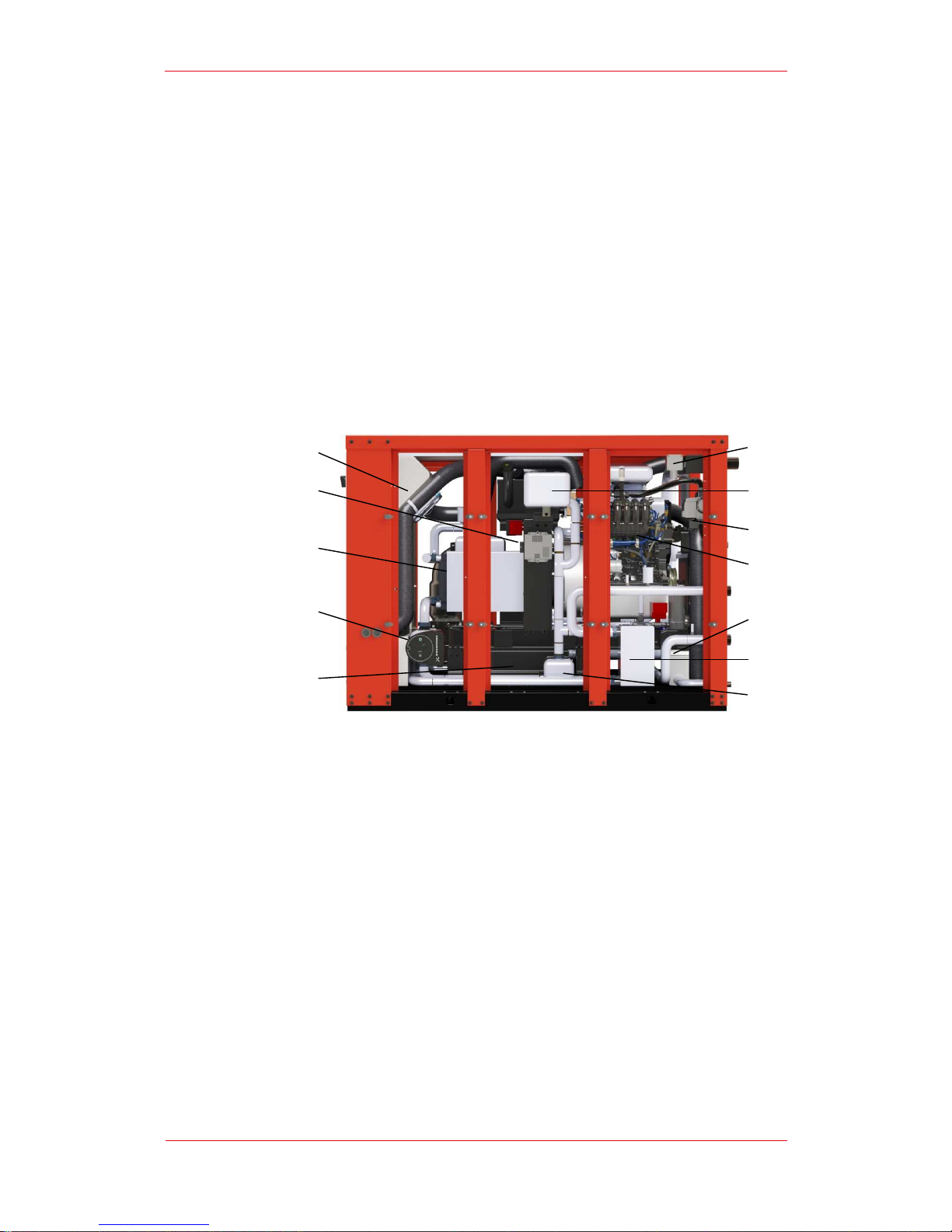
D.
TOTEM - Layout of Components
1. Enclosure air vent
2. ARYA control unit
3. Water cooled synchronous generator
4. Engine water circulator pump
5. Spent oil tank
6. Thermostatic valve
7. Water to water plate heat exchanger
8. Condensate collector tray
9. FIAT FIRE endothermic engine
10. Zero governor valve
11. Water tray
12. Methane gas safety detector
1
2
5
3
4
11
12
6
9
10
8
7
Page 15
User’s Guide | TOTEM 10 - TOTEM 20
15 of 30
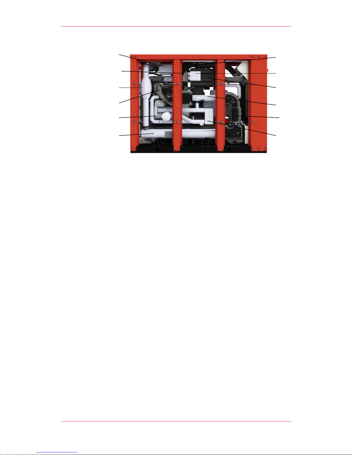
13. Engine air filter
14. Safety frame structure temperature sensor
15. Exhaust silencer
16. Exhaust manifold
17. Oil filter
18. Fumes to water tube bundle heat exchanger
19. Water to oil plate heat exchanger
20. Marelli three-way catalyst
21. Water to fumes coaxial heat exchanger
22. Fresh oil tank
23. Marelli ECU
24. Engine air suction snorkel
E.
Safety Instructions
The TOTEM is equipped with EN ISO 13849 compliant safety systems so as to
protect machine operators and maintenance staff against hazards linked to the
micro-cogenerator operation.
Risk analysis has identified the following hazards:
Exhaust gas emissions
Lack of water flow
Spark advanced with temperature increase
Methane gas leak
The system is composed of a chain of safety sensors: an electromechanical
thermostat, a methane gas sensor, and an emergency pushbutton.
Methane gas leakage hazard
The TOTEM is fitted with a catalythic methane gas sensor for gas leaks. The sensor
features a two-threshold calibration that trigger safety system activation when gas
leaks are detected inside the unit’s enclosure. The first threshold value is set to 20%
of LEL. Values exceeding threshold are sent to the ARYA PLC that will command the
13
14
17
15
16
23
24
18
21
22
20
19
Page 16

User’s Guide | TOTEM 10 - TOTEM 20
16 of 30
unit to turn off thus restoring safety conditions. The second threshold value is set to
50% of LEL, exceeding of this values is reported directly to the safety relay that is
actuated even in the event of PLC malfunctioning, closing the gas supply valve and
turning the unit off.The electrical switchboard terminal block includes a contact for
connection to the natural gas solenoid of the central heating system. In the event of
a gas leak, the relay opens this circuit, too, by commanding valve closure.
Exhaust Gas Emission Hazard, Lack of Water Flow Hazard, Timing variation
Hazard
The above mentioned occurrences can pose a danger by causing an increase in
temperature which may cause some of the unit’s parts to become hot thus putting
the operator at risk of burns, or by causing a discharge of exhaust gases that
upstream of the catalyst feature a high carbon monoxide content.
These anomalies can be detected by a safety thermostat fitted inside the unit’s
enclosure and calibrated to actuate the emergency relay upon reaching 75°C, which
willl switch the unit off. This is a certified system guaranteeing high reliability even in
the event of a failure of all other control systems fitted onto the TOTEM.
Emergency Pushbutton
The Operator Panel features an emergency pushbutton that can be pressed in the
event of any risk situation. The emergency pushbutton actuates the emergency relay
that will switch the micro cogenerator off thus restoring safety.
In order to ensure proper functioning of the safety devices and, consequently,
Totem’s operation under fully safe conditions, the following requirements must
mandatorily be met upon installation:
- The central heating system solenoid must be connected to the specially
devised terminal block located on the TOTEM electrical switchboard;
- Proper room ventilation – at least 600 m
3
/h must be ensured or,
alternatively, enough windows must be provided in the room so as to
ensure an equivalent ventilation rate according to volumes, or a CO sensor
must be installed in the central heating system.
Page 17
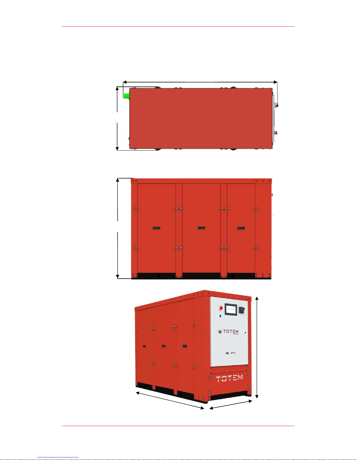
F.
Size and
770 mm
1.280 mm
User’s Guide | TOTEM 10
Overall Dimensions
1,810 mm
1,810 mm
770 mm
- TOTEM 20
17 of 30
1.
280 mm
Page 18
G.
Control Switchb
Machine Operators can operate the machine solely by using the controls available on
the control
remains strictly forbidden due to the presence of energized and hot parts.
The Control switchb
G
E
C
B
User’s Guide | TOTEM 10
oard
switchboard; acces
s to the inside of the Control switch
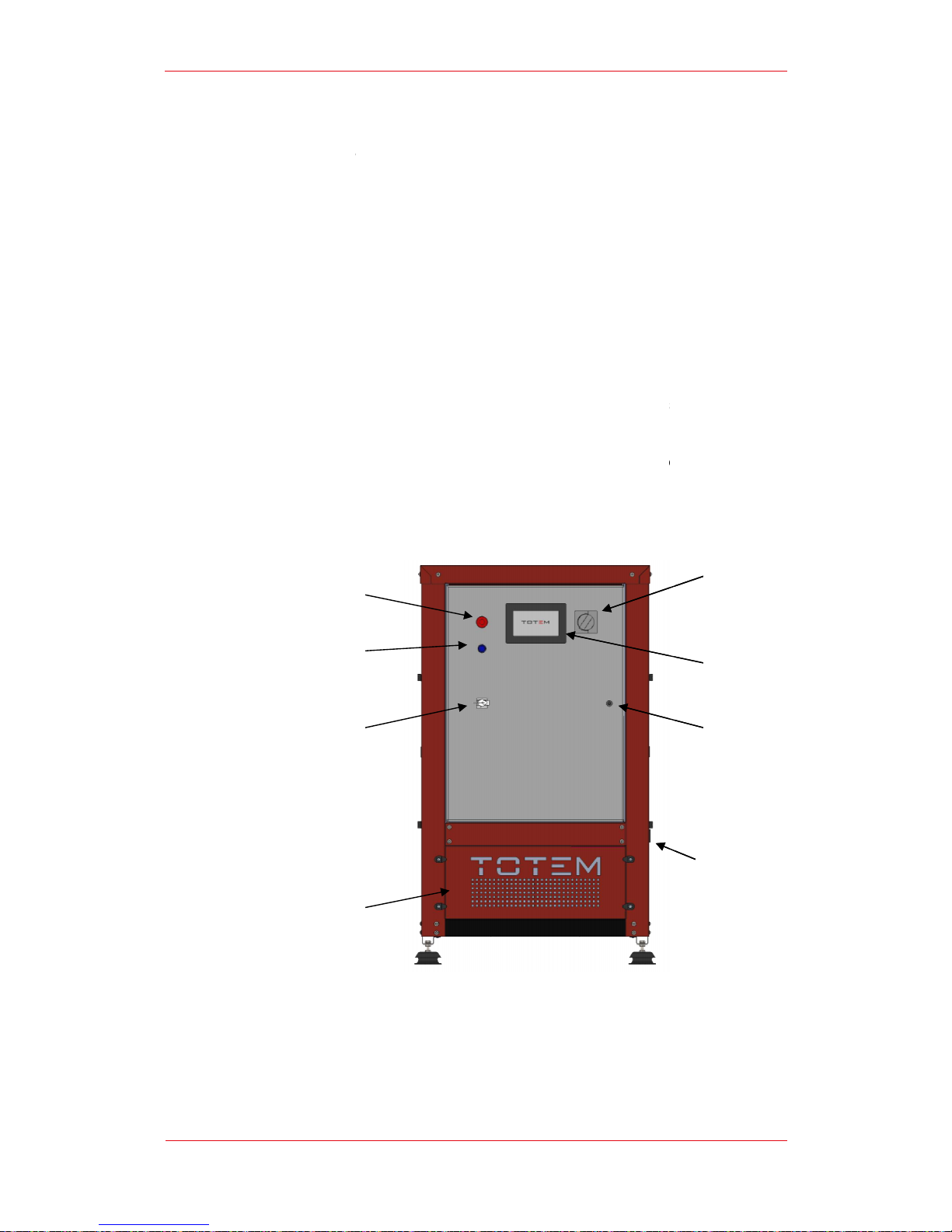
oard features the following control devices:
Main Switch (A): by operating the Main Switch
, any so
supply is interrupted and the unit i
s disconnected from the power grid
Emergency pushbutton (B):
in the event of an emergency, the unit can
be switched off by pressing the emergency pushbutton;
Emergency relay manual reset pushbutton (C):
if the unit is switched
off by means of the emergency pushbutton or following activation of
one of the alarms along the safety chain (high temperature or methane
leak) , the emergency relay must be manually reset by pressing the
reset button before restarting the unit;
Operator Panel (D): it consists of a LCD
7” touchscreen
displays all the unit’s operating info and enabling operators to enter all
relevant commands;
LAN connection (E): the LAN port enables con
nection to other devices
providing access the operator panel.
A: Main Switch
B: Emergency Pushbutton
C: Emergency Relay Manual Reset Button
D: Operator Panel
E: LAN connection
- TOTEM 20
18 of 30
oard cabinet
urce of power
;
monitor that
H
F
D
A
Page 19
The Electrical Board and Air intake compartment can be opened with a special key
solely by authorized personnel.
H.
Connection
All process connec
side,
opposite to the Control Switchb
The c
onnection
In
a standard configuration, process connections must fulfill the following
requirements:
A
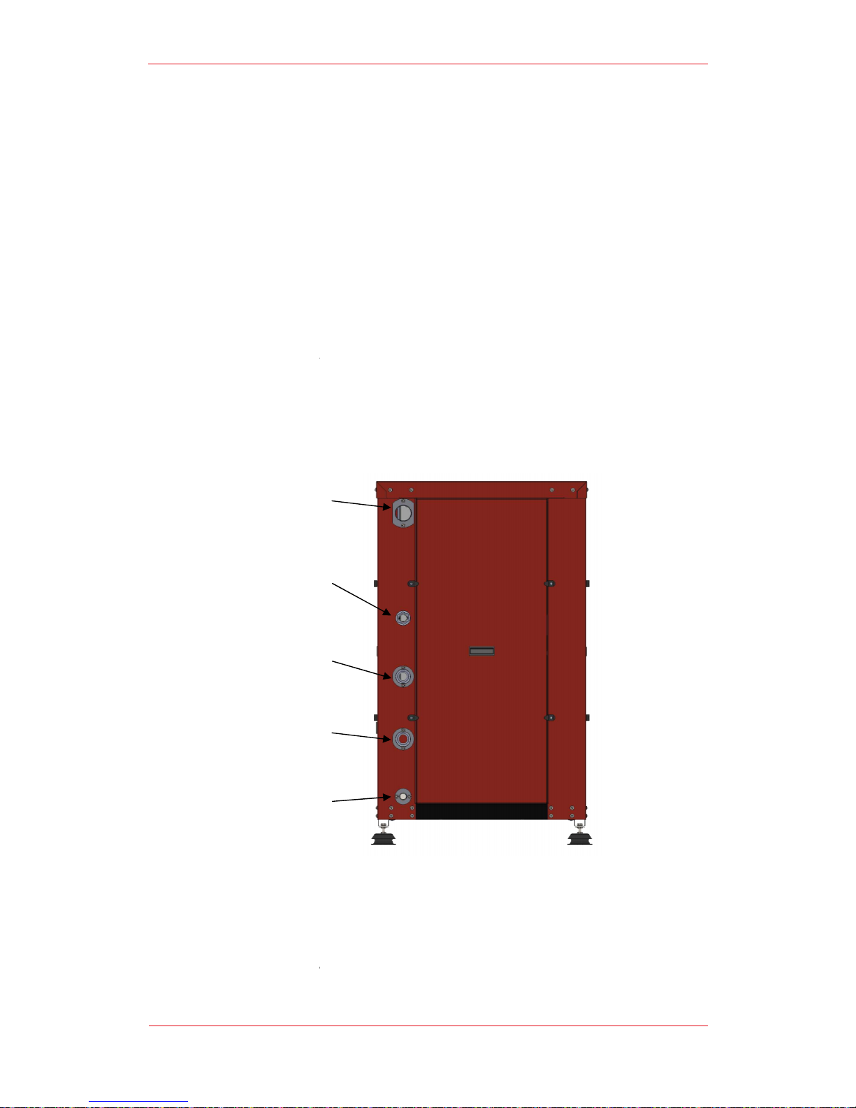
: Fumes discharge
B:
Fuel gas supply (natural gas
C:
User water outlet
D: User water inlet
E: Condensate drain
A
B
C
D
E
User’s Guide | TOTEM 10
F: Control switchboard lock
G: Air intake compartment
H: Power cable entry
Panel
tions are located on one of the vertical members of the unit’s back
oard.
s’ position is shown in figure.
Fumes discharge :2” GTAS female
Natural gas connection: ¾” GAS female
User Water outlet: 1” ¼ GAS female
User Water inlet : 1” ¼ GAS female
Condensate Drain: ¾” GAS female
)
- TOTEM 20
19 of 30
Page 20

User’s Guide | TOTEM 10 - TOTEM 20
20 of 30
I.
Noise Emissions and Vibrations
Thanks to its high-quality technical solutions and its high-performing sound insulation
materials, the TOTEM® units feature low noise emissions.
The data shown in the technical datasheet are measured at 1 m distance, free-field,
as per standards.
Despite its carefully selected sound-insulating, vibration-damping materials, when in
operation the TOTEM® unit can generate small vibrations that may in some cases be
transferred to surrounding structures.
For extremely sound sensitive applications, additional solutions may be necessary to
further reduce noise and vibrations.
4.
Use of the Micro Cogenerator
A.
Preparing the Unit for Use
Before starting the unit, ensure that all connections described in the Installation
Guide have been performed correctly.
All installation procedures must be performed solely by Qualified Technicians.
A description of said procedures is provided in the Installation Guide.
In all cases, commissioning must be performed solely by authorized Totem Energy
personnel by calling the Technical Support Service. Carrying out commissioning
without the supervision of Totem Energy authorized personnel will nullify the
warranty.
In the event that the unit has to be restarted after prolonged inactivity, we
recommend calling the Technical Support Service.
Once all connections to the User systems have been checked, it is possible to
operate the Main Switch thus powering the Electrical Board and switching the
Touchscreen Operator Panel on. the Panel’s display will become operational after a
few minutes.
TOTEM units use air for combustion. The proper amount of air for recirculation in the
room - 600 m3/hour - must also be provided through suitably sized openings in the
building envelope. Such airflow inlets must not interfere with pre-existing openings, if
any, created for other devices or heat generators.
To ensure the unit’s proper functioning, the ambient operating temperature must
range between 1°C and 40°C.
For applications with ambient temperatures that may, even occasionally, be equal to
or lower than 0°C, it is mandatory to treat the user system’s water properly and add
an anti-freeze solution in suitable concentration.
For applications in areas with ambient temperatures that may, even occasionally, get
lower than -15°C, it is mandatory to properly treat the micro cogenerator’s internal
circuit coolant, too. Please contact TOTEM ENERGY’s Technical Support Service.
Page 21
B.
Operator
The Operator
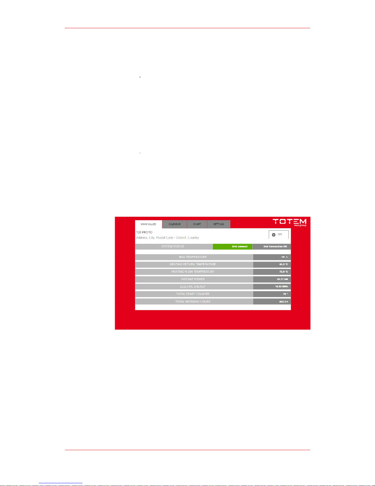
Main values
The figure shows the Panel’s main screenshot.
The start button is found i
When the unit is
meaning that pressing the button will enable the unit to start.
When the unit is in operation, the button will display the word
pressing the button the unit will be switched off.
The screenshot also shows the following items
User’s Guide | TOTEM 10
Panel
panel consists of a 7”
touchscreen monitor featuring 4 screenshots
Main values
Calendar
Charts
Settings
n the screenshot’s upper right corner.
switched off, the word “ON” will be displayed on the button
“OFF”
:
System status
Instant power output
Total start counter
Total working hours
- TOTEM 20
21 of 30
:
meaning that by
Page 22
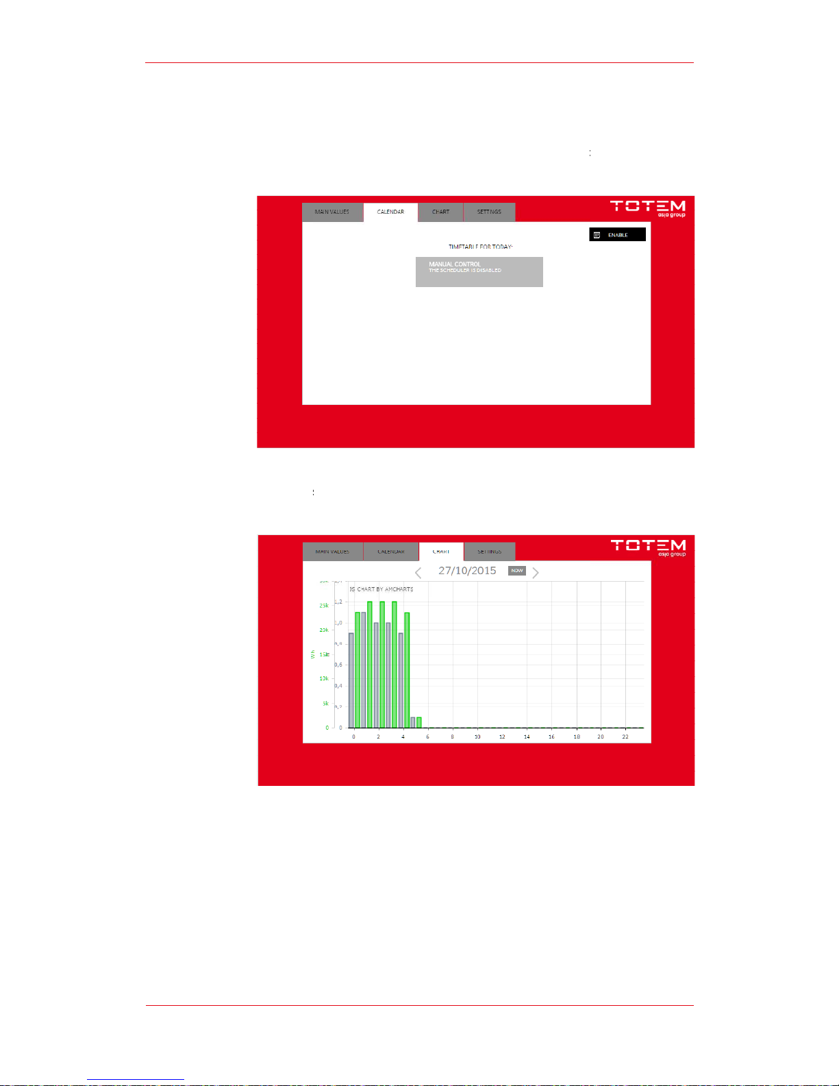
Calendar
From the “Calendar” screenshot, it is
switch the unit
Charts
The
“Charts”
working hours
User’s Guide | TOTEM 10
possible to enable a scheduler function to
on, on a given time slot.
screenshot displays the charts for the total power output and total
.
- TOTEM 20
22 of 30
Page 23
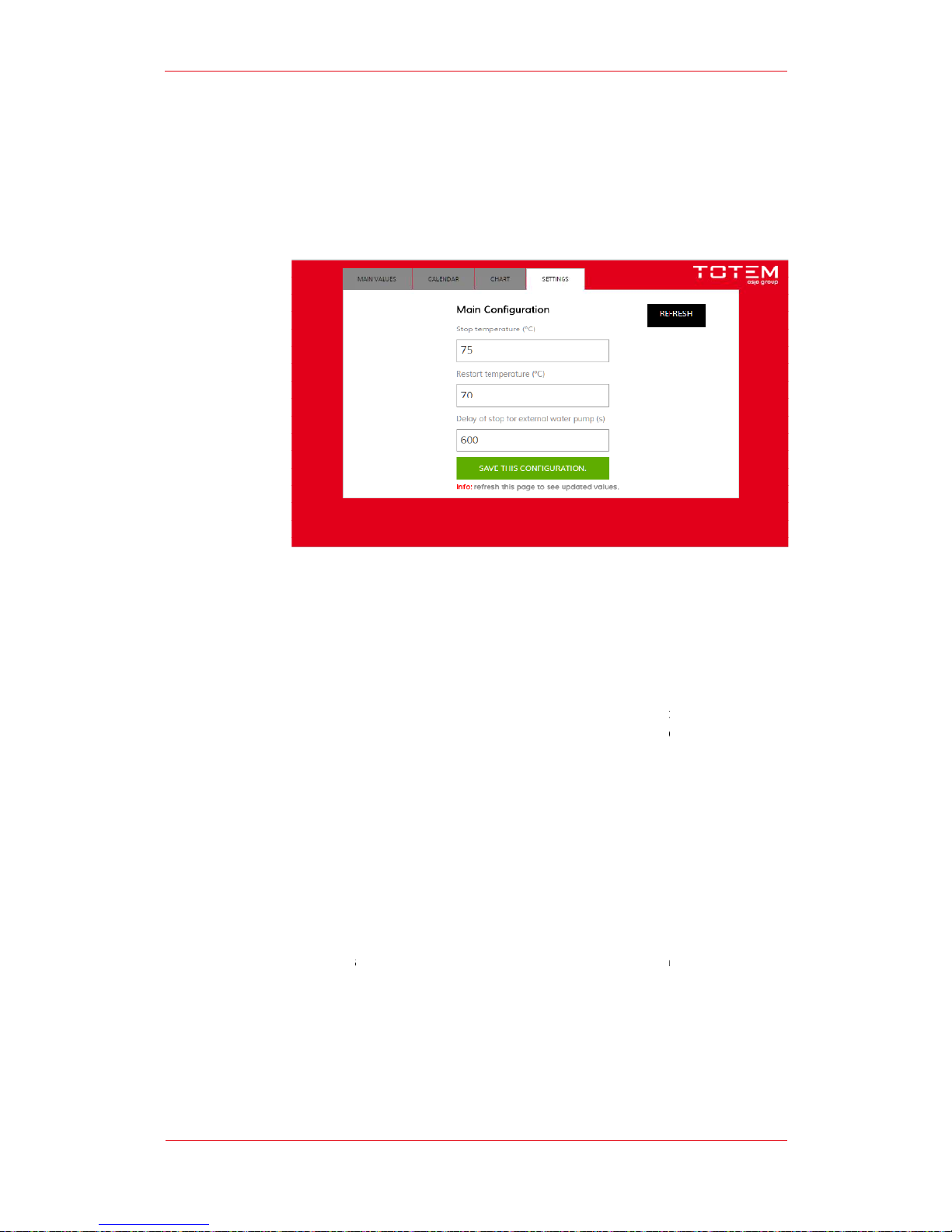
Settings
The “Settings” sreenshots
C.
Start
TOTEM
units work based on the “thermal
automatically
load is
present
TOTEM
unit.
In addition to fulfillin
by the User by operating
Once start is
under the following
The t
emperature value can be set in
in the range from
In addition to the start temperature
set. When the temperature of water
unit
automatically
The unit is
also
the pump start command
commanded to stop with a delay that can be set by the user. The delay is
let water circulate
User’s Guide | TOTEM 10
allows to set some of the unit’s operating parameters
Start temperature
Stop temperature
External pump stop delay
ing and Working Principle
priority” principle,
that
switch to simultaneous
delivery of heat and electricity
that allows to recover heat from the internal
recovery
g the aforementioned condition
, the unit’s Start must
the “ON” button that is found on
the Operator panel.
enabled, the TOTEM starts functioning fol
lowing a demand
conditions:
Activation of the User’s Water system circulator
pum
the unit’s on-board flow switch;
Water temperature below the value set by the User.
the “Setting
s” screenshot on the Operator Panel
30 to 70°C.
value
, the stop temperature
from the supply line
exceeds the set value, the
stops, going into stand-by mode.
also
fitted with an external
pump control outlet. When the st
is also enabled. When the unit
stops,
within the unit after it is switched off thus
allowing
- TOTEM 20
23 of 30
is to say, they
whenever a heat
system of the
be enabled
for heat
p, as detected by
value will also be
art is enabled
the pump is also
needed to
it to cool down.
Page 24

User’s Guide | TOTEM 10 - TOTEM 20
24 of 30
D.
Operating Conditions
Under standard operating conditions, the units work under fixed point steady state
mode.
Electric power output is equal to10 and 20 kW, respectively.
Thermal power depends on user water inlet temperature and it can range from 20 to
22 kW and from 42 to 47.5 kW, for the two models respectively.
Inlet temperature can vary from a maximum of 72°C to 35°C. Water flow rate must
be between 2 and 4 m3/h. Outlet temperature depends on inlet temperature and
flow rate. Thermal gradient can vary from 5 to 11°C according to water flow rate.
Methane feeding pressure must be in the range of 20mbar +/- 5%.
Engine exhaust fumes temperature is approximately 720° for the TOTEM 20 and
620°Cfor the TOTEM 10. Fumes stack temperature is comprised between 60 and
80°C.
E.
Fuel Characteristics
The TOTEM can run on natural grid gas. Said fuel gas must fulfill the requirements of
quality for natural gas.
The parameters for Quality Control are listed hereunder:
Higher Heating Value (HHV): 34.95÷45.28 MJ/Sm
3
Wobbe Index:47.31÷52,33
Relative density: 0.5548÷0.8
Oxygen: < 0.6 %mol
Water dew point: <= -5°C
Hydrocarbon dew point:<=0°C
Max temperature: <50°C
Carbon dioxide: <= 3%mol
Polluting compounds are tolerated within the following thresholds:
Hydrogen Sulphide<= 6.6 mg/Sm
3
Mercaptans<= 15.5 mg/Sm
3
Total Sulphur<= 150 mg/Sm
3
Under operating conditions, the gas used must not contain traces of water or liquid
state hydrocarbons, solid particulate matter or other elements that may impact
safety.
Gas pressure at the TOTEM inlet must be higher than10 mbar. Lower pressure values
may generate an error alert.
The natural gas consumption data shown in the technical datasheets refer to natural
grid gas with a Lower Heating Value of 10 kWh/Nm3 (PCS 11.25 kWh/Nm3).
Page 25

User’s Guide | TOTEM 10 - TOTEM 20
25 of 30
F.
User System’s Water Characteristics
TOTEM’s process water cannot be directly drawn off the domestic hot water or
drinking water circuit. Appropriate hydraulic separation systems must be installed for
said applications.
The water used in the user circuit must fulfil the requirements provided in nationale
standards and have the following chemical and chemical/physical parameters for
water in heating systems for civilian applications:
Clear appearance ;
pH above 7 (below 8 for the user system’s sections made in light alloys,
if any)
iron (as Fe) < 0.5 mg/kg (higher values indicate presence of corrosion
that must be removed before connection to the TOTEM® unit);
copper (as Cu) < 0.1 mg/kg (higher values indicate presence of
corrosion that must be removed before connection to the TOTEM unit).
Further provisions also require to:
fill the heating system with water having a low limestone content, with
a French degree of water hardness between 15°F and 25°F, based on
the installed capacity and the system’s overall content;
Therefore, it is mandatory to install a suitable water treatment system on heating
systems that do not comply with the limits imposed.
The limits set by the aforementioned provisions and supplemented by legal
provisions and regulations in force in the place of installation are aimed to:
optimize TOTEM®’s and user systems’ performance and reliability;
guarantee system safety;
preserve the systems’ components over time;
ensure regular functioning of auxiliary equipment;
minimize energy consumption.
Using suitably treated water for the user water system serves the dual purpose of
ensuring compliance with applicable regulations and TOTEM ENERGY’s / leading heat
generator manufacturers’ recommendations, and contributing to reducing operating
costs and consumption.
For applications featuring an environment temperature below 1°C, an anti-freeze
mixture (glycol) must be added to the user circuit. Depending on its glycol content,
the water/anti-freeze mixture may reduce the heat exchange capacity and heating
output.
Frequent refilling of the circuit should be avoided. Care should be taken in choosing
water softening techniques based on deionization and cation exchange. We advise
against using chemical additives as they may cause harmful dirt/residues to
precipitate and possibly damage the system.
Page 26

User’s Guide | TOTEM 10 - TOTEM 20
26 of 30
If the TOTEM® is installed in pre-existing heating systems that may be subject to
deterioration, including corrosion, algae formation, limescale build-up, or dirt
deposits, the user system should be preemptively flushed with appropriate products
depending on the problem identified. In some specific cases, a suitable hydraulic
separation device (exchanger) shall have to be installed to protect the TOTEM® ‘s
internal circuit from possible damages and avoid treating the preexisting systems too
aggressively.
G.
Emergency Stop and Shutdown
The TOTEM® can be switched off manually by the User from the Control
switchboard or following the reaching of the pre-set supply temperature, or even
following activation of an alarm signal.
The Arya PLC developed by Totem Energy monitors a set of parameters for engine
functioning and it governs the unit’s shutdown in case a value exceeding the
manufacturer’s preset range is detected.
In addition to being governed by the PLC, the TOTEM® shutdown can also follow
actuation of the emergency relay. Namely, the safety line can be activated in the
presence of the following potentially dangerous malfunctions:
Push the Emergency button
High temperature within the unit’s enclosure detected by the
temperature limiter
Methane detected by the unit’s on-board sensor
H.
Calendar
Through the Calendar function, it is possible to program the Unit to start on set days
and time ranges.
With the Calendar function disabled, the unit will only start following manual input by
the operator from the operator panel.
With the Calendar function enabled, the unit will only be switched on on the days
and time ranges set by the User.
I.
Diagnostics
If the machine is shut down following a command by the PLC, an alarm signal is
displayed on the control switchboard.
The alarm signal can be reset to enable unit’s restart. If the alarm stays on, the unit
won’t start. If that occurs, call the Technical Support Service.
If the unit was switched off due to activation of the safety devices, alongside the
alarm the emergency relay reset button will also light up.
To restart the unit, press the emergency relay manual reset button and reset all
alarms on the Control switchboard.
Page 27

User’s Guide | TOTEM 10 - TOTEM 20
27 of 30
5.
Remote Control
A.
Local Area Network Connection
It is possible to connect a portable device to the Control Switchoard. Connection can
be set up via the lan port located on the control switchboard or through a wi-fi
network.
It is possible to connect a laptop or a tablet to access the Operator’s panel
screenshot using a browser.
To enable access, a static IP address must be set on the device to be connected.
The IP to be used for device connection is: 192.168.5.x (where x is any number
other than 1).
Once the static IP address has been set, open your browser (Internet Explorer,
Mozilla, Chrome or others) and enter the following address http://192.168.5.1:8080
The login page will be shown on screen. Enter your username and password.
This will give you access to the User’s screenshot.
The list of parameters that can be viewed thorugh the Operator’s panel (or
smartphone) or via connection with a laptop/tablet is provided hereunder.
Operators Panel or Smartphone
Max water temperature at outlet engine stop
Min water temperature at outlet engine restart
External circuit water circulator pump stop delay
Electric power produced in kW - 2 decimals
Electric power produced
Magneti Marelli diagnostic code
Water temperature at TOTEM inlet
Water temperature at TOTEM outlet
Temperature inside the unit
Grid connected working hours
Maintenance interval down-counter
Machine Status and Step
Laptop – Tablet
Max water temperature at outlet engine stop
Min water temperature at outlet engine restart
External circuit water circulator pump stop delay
Electric power generated as kW - 2 decimals
Electric power generated
Electric Power generated on L1 phase line
Page 28

User’s Guide | TOTEM 10 - TOTEM 20
28 of 30
Electric power generated on L2phase line
Electric power generated on L3 phase line
Voltage on L1 phase line
Voltage on L2 phase line
Voltage on L3 phase line
Current generated on L1 phase line
Current generated on L2 phase line
Current generated on L3 phase line
Mains frequency
Power factor (power factor correction)
Magneti Marelli diagnostic code
Water temperature at TOTEM inlet
Water temperature at TOTEM outlet
Temperature inside the unit
Grid-connected working hours
Maintenance interval down-counter
Maintenance Interval Incremental Index
Machine Status and Step
Machine Active Alarm Vector
B.
Remote Connection
Remote connection allows to access one or more units’ historical data log. Once a
day a data packet containing the operating data recorded every 15 seconds,
alongside alarm history, if any, is sent by the TOTEM to cloud.
To set up a remote connection users just have to open any web browser and enter
the following address: http://totem.whiteqube.it . They will be redirected to the login
page, where username and password must be entered. In addition to viewing
historical data, it is also possible to set up a real-time connection with the unit, so as
to check unit status and/or modify the operating parameters. The real-time
connection maximum duration is 15 minutes. The use of real-time connection is
subject to payment of a fee according to the subscription agreement terms.
Page 29
User’s Guide | TOTEM 10 - TOTEM 20
29 of 30
6.
Maintenance
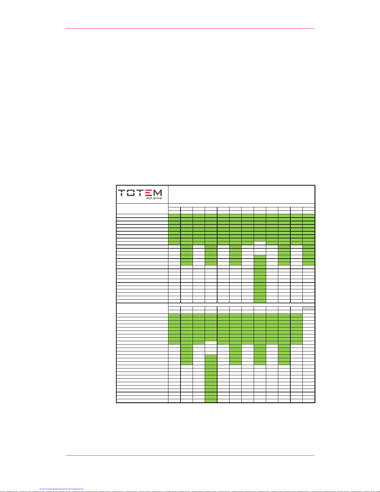
Scheduled Maintenance shall be perfomed according to the maintenance plan shown
in the tables hereunder for each type of Unit.
The Mainenance Plan provides for three types of operation, to be carried out with
different timing according to model:
T1 – to be carried out every 2,500/3,000 hours
T2 – to be carried out every 5,000/9,000 hours
T3 – to be carried out every 20,000/36,000 hours
Detailed instructions on how to carry out basic maintenance operations are provided
in the Service Manual.
TOTEM 20 MAINTENANCE PLAN
0-60,000 hours
2501 5001 7501 10001 12501 15001 17501 20001 22501 25001 27501 30001
T1 T2 T1 T2 T1 T2 T1 T3 T1 T2 T1 T2
Machine check up X X X X X X X X X X X X
Fastener and hose torque and check X X X X X X X X X X X X
Electrical connection torque and check X X X X X X X X X X X X
Engine coolant level check X X X X X X X X X X X X
Engine oil rep lacement/tank refill X X X X X X X X X X X X
Engine oil f ilters replaceme nt X X X X X X X X X X X X
Secondary air filter replacement X X X X X X X X X X X X
Valve gap check and setting X X X X X X X X X X X X
Spark plug replacement X X X X X X X X X X X
Cylinder head replacement X X X X X
Spark plug cables replacement X X X X X
Distribution belt and tensioner replacement X X X X X
Engine coolant replacement X X X X X X
Lambda probe replacement (pre catalytic converter) X X X X X X
Primary air filter replacement X X X X X X
Lambda probe replacement (post catalytic converter) X
Exhaust gas heat exchanger cleaning (fumes side) X
Water heat exchanger cleaning (user water side) X
Three way catalyzer replacement X
Engine Replacement X
Engine Starter replacement X
Battery replacement X
CH4 leaking sensor check X
Gas actuator replacement X
Flexible tubes replacement X
Insualtions replacement X
32501 35001 37501 40001 42501 45001 47501 50001 52501 55001 57501 60000
T1 T2 T1 T3 T1 T2 T1 T2 T1 T2 T1
Machine check up X X X X X X X X X X X
Fastener and hose torque and check X X X X X X X X X X X
Electrical connection torque and check X X X X X X X X X X X
Engine coolant level check X X X X X X X X X X X
Engine oil rep lacement/tank refill X X X X X X X X X X X
Engine oil f ilters replaceme nt X X X X X X X X X X X
Secondary air filter replacement X X X X X X X X X X X
Valve gap check and setting X X X X X X X X X X X
Spark plug replacement X X X X X X X X X X
Cylinder head replacement X X X X
Spark plug cables replacement X X X X
Distribution belt and tensioner replacement X X X X
Engine coolant replacement X X X X X
Lambda probe replacement (pre catalytic converter) X X X X X
Primary air filter replacement X X X X X
Lambda probe replacement (post catalytic converter) X
Exhaust gas heat exchanger cleaning (fumes side) X
Water heat exchanger cleaning (user water side) X
Three way catalyzer replacement X
Engine Replacement X
Engine Starter replacement X
Battery replacement X
CH4 leaking sensor check X
Gas actuator replacement X
Flexible tubes replacement X
Insualtions replacement X
Service hiùur
Job
Job
MAINTENANCE PLAN "EXCELLENT" TOTEM 20 0-60.000 hour
Service Hour
Page 30
User’s Guide | TOTEM 10 - TOTEM 20
30 of 30
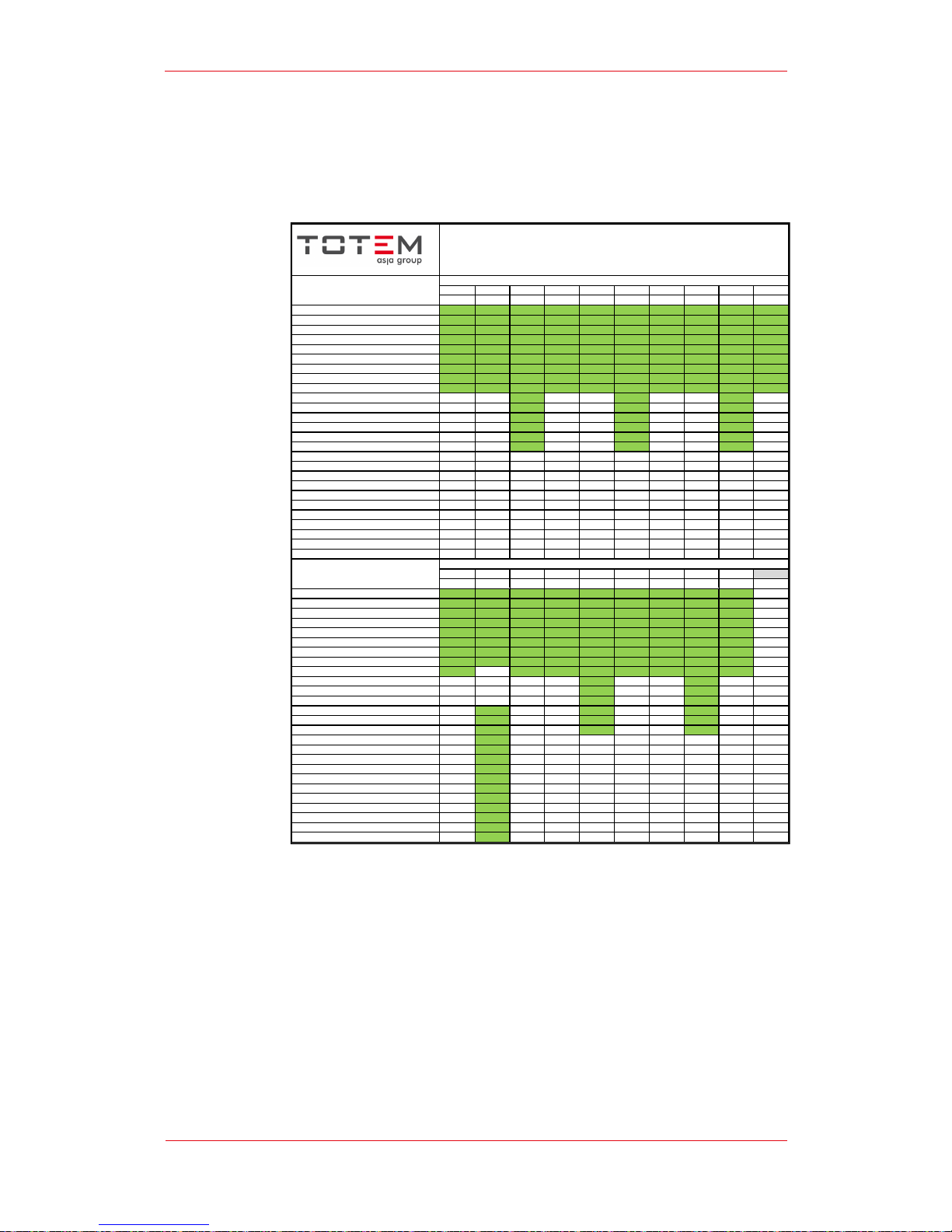
TOTEM 10 MAINTENANCE PLAN
0-60,000 hours
3001 6001 9001 12001 15001 18001 21001 24001 27001 30001
T1 T1 T2 T1 T1 T2 T1 T1 T2 T1
Machine check up X X X X X X X X X X
Fastener and hose torque and check X X X X X X X X X X
Electrical connection t orque and check X X X X X X X X X X
Engine coolant le vel check X X X X X X X X X X
Engine oil replacement/tank refill X X X X X X X X X X
Engine oil f ilt ers replaceme nt X X X X X X X X X X
Secondary air filter replacement X X X X X X X X X X
Valve gap check and setting X X X X X X X X X X
Spark plug replacement X X X X X X X X X X
Cylinder head replacement X X X
Spark plug cables replacement X X X
Distribution belt and tensioner replacement X X X
Engine coolant replacement X X X
Lambda probe replacement (pre catalytic converter) X X X
Primary air filter replacement X X X
Lambda probe replacement (post catalytic converter)
Exhaust gas heat exchanger cleaning (fumes side)
Water heat exchanger cleaning (user water side)
Three way catalyzer replacement
Engine Replaceme nt
Engine Starter replacement
Battery replacement
CH4 leaking sensor check
Gas actuator replacement
Flexible tubes replacement
Insualtions replaceme nt
33001 36001 39001 42001 45001 48001 51001 54001 57001 60000
T1 T3 T1 T1 T2 T1 T1 T2 T1
Machine check up X X X X X X X X X
Fastener and hose torque and check X X X X X X X X X
Electrical connection t orque and check X X X X X X X X X
Engine coolant le vel check X X X X X X X X X
Engine oil replacement/tank refill X X X X X X X X X
Engine oil f ilt ers replaceme nt X X X X X X X X X
Secondary air filter replacement X X X X X X X X X
Valve gap check and setting X X X X X X X X X
Spark plug replacement X X X X X X X X
Cylinder head replacement X X
Spark plug cables replacement X X
Distribution belt and tensioner replacement X X
Engine coolant replacement X X X
Lambda probe replacement (pre catalytic converter) X X X
Primary air filter replacement X X X
Lambda probe replacement (post catalytic converter) X
Exhaust gas heat exchanger cleaning (fumes side) X
Water heat exchanger cleaning (user water side) X
Three way catalyzer replacement X
Engine Replaceme nt X
Engine Starter replacement X
Battery replacement X
CH4 leaking sensor check X
Gas actuator replacement X
Flexible tubes replacement X
Insualtions replaceme nt X
Job
Job
MAINTENANCE PLAN "EXCEL LENT" TOTEM 10 0-60.000 hour
Service hour
Service Hour
 Loading...