

Total Protection Solutions TransTrack 50, TransTrack 100, TransTrack 160, TransTrack 200 Operation Manual
Page 1

®
Surge
Total Protection
Solutions
®
Protective
Devices
TransTrack Series:
50, 100, 160 and 200
Installation,
Operation and
Maintenance
Manual
TRANSTRACK™INSTALLATION, OPERATION AND MAINTENANCE MANUAL
Page 2

TABLE OF CONTENTS
Introduction
Before Installation
System Configuration Verification
Wiring Connection Diagrams
Upstream Over-Current Protection Device
Raceway
Wire Length and Conductor Routing
Mounting
Connection and Wiring Instructions
Phase, Neutral and Ground Connections
Connecting Form C Dry Contacts
Verification and Power Up
Troubleshooting
3
4-6
4
5
6
6
6
6
6-7
6
7
7
7
Technical Assistance
Returns and Warranty Procedures
Warranty Statement
7
7
8
2
TRANSTRACK™INSTALLATION, OPERATION AND MAINTENANCE MANUAL
Page 3
INTRODUCTION
!
INTRODUCTION
®
Today’s sophisticated electronic equipment requires reliable surge protective devices. By selecting Joslyn
Solutions™, TransTrack™devices, you have taken a critical step toward decreasing downtime and ensuring longer product life
for your equipment.
TransTrack is designed to protect facilities and sensitive electrical and electronic equipment against the harmful effects of
lightning strikes and internally generated electrical transients. These reliable surge protection devices fulfill the single-pulse
surge current capacity testing recommendations per NEMA LS-1, 1992, sections 2.2.9 and 3.9.
TransTrack combines easy installation with many special features to deliver more performance than any other device in its
class.
TransTrack is conveniently pre-wired with 24-inch, stranded #10 AWG pigtail conductors. To ensure optimum product
performance, install your TransTrack system in a location that minimizes wire lengths and wire bends. This positioning
maximizes surge suppression and filtering while providing added protection for the connected loads.
STRIPE COLOR MODULE TYPE
,Total Protection
WARNING: HAZARDOUS VOLTAGES PRESENT Improper installation or misapplication may result in
serious personnel injury and/or damage to electrical system. Read the complete installation instructions before
proceeding with installation. Remove all power to the electrical panel before installing or servicing the
suppressor.
IMPORTANT SAFETY INSTRUCTIONS All work must be performed by licensed and qualified personnel. The electrical
system must be properly grounded in accordance with the U.S. National Electrical Code, state and local codes or other
applicable codes for this suppressor to function properly. Do not connect TransTrack to the line side of the main service
breaker or disconnecting means. This device is suitable for installation where the available short circuit current is
65,000 RMS symmetrical amperes at 480VAC or less.
TRANSTRACK™INSTALLATION, OPERATION AND MAINTENANCE MANUAL
3
Page 4

BEFORE INSTALLATION
!
1. System Configuration Verification:
Confirm that the voltage(s) and service configuration shown on TransTrack product label are consistent with the voltage and
service configuration of the facility. A model number is on the bottom side of TransTrack. Each model number
corresponds to the configurations printed in the table below:
Example of a suppressor model number: TK-TT200-3Y208-F
MODEL NUMBER
TK-TTxxx-1P240 204-264 N/A
TK-TTxxx-1S240 102-132 204-264
TK-TTxxx-3Y208 102-132 177-229
TK-TTxxx-3Y380 220/380 187-264 323-460
TK-TTxxx-3Y415 204-264 353-457
TK-TTxxx-3Y480 236-305 408-528
TK-TTxxx-3D240 120/240
TK-TTxxx-240NN N/A 204-264
TK-TTxxx-380NN 380 N/A 323-460
NOMINAL L-N L-L
VOLTAGE VOLTAGE RANGE VOLTAGE RANGE
240
120/240
120/208
240/415
277/480
(A & C PHASES)
240
102-132
177-229
(B PHASE)
204-264
CONFIGURATION
Single-Phase,
2-wire+ground
Split-Phase,
3-wire+ground
Three-Phase WYE
4-wire+ground
Three-Phase WYE
4-wire+ground
Three-Phase WYE
4-wire+ground
Three-Phase WYE
4-wire+ground
Three-Phase high-leg DELTA
4-wire+ground
Three-Phase DELTA
3-wire+ground
Three-Phase DELTA
3-wire+ground
TK-TTxxx-480NN N/A 408-528
-F suffix denotes enhanced transient filter (ETF) option.
The ETF option is not recommended for applications employing a Ground Fault Current Interrupting (GFCI) breaker.
480
WARNING: Check to ensure that a proper bond is installed between neutral and ground at the transformer
upstream from all 3-phase WYE, 3-phase high-leg DELTA, split-phase or single-phase TransTrack device (see
NEC article 250). If the transformer is not accessible, check the main service disconnect/panel for the N-G
bond. Lack of a proper bond will damage TransTrack and void the warranty.
Three-Phase DELTA
3-wire+ground
4
TRANSTRACK™INSTALLATION, OPERATION AND MAINTENANCE MANUAL
Page 5
2. Wiring Connection Diagrams
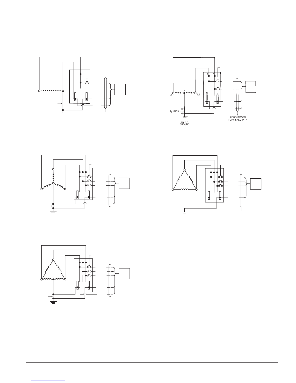
Figures 1-5 show the electrical relationship between TransTrack and these five basic service configurations: Single-phase,
2-wire, Split-phase, 3-wire; Three-phase, 4-wire WYE, Three-phase, 3-wire DELTA and Three-phase, 4-wire high-leg DELTA.
Fig. 1: 1-Phase, 2-Wire Fig. 2: Split Phase, 3-Wire
20 AMP, 1-POLE
CIRCUIT BREAKER
L1
TRANSTRACK
PHASE A
L1
BOND
X
O
G
EARTH
GROUND
N
NG
GREEN/
YELLOW
WHITE
TK-TTxxx-1P240
CONDUCTORS
FURNISHED WITH
TRANSTRACK
20 AMP, 2-POLE
CIRCUIT BREAKER
PHASE A
PHASE B
GREEN/
YELLOW
WHITE
TRANSTRACK
TRANSTRACK
TK-TTxxx-1S240
Fig. 4: 3-Phase, 3-Wire DELTAFig. 3: 3-Phase, 4-Wire WYE
20 AMP, 3-POLE
CIRCUIT BREAKER
PHASE A
PHASE B
BRED
PHASE C
ORN
GREEN/
YELLOW
CONDUCTORS
FURNISHED WITH
TRANSTRACK
TRANSTRACK
TK-TTxxx-xxxNN
X
C
O
BOND
N
N
G
EARTH
GROUND
20 AMP, 3-POLE
B
NG
A
CIRCUIT BREAKER
PHASE A
PHASE B
PHASE C
ORN
GREEN/
WHITE
CONDUCTORS
FURNISHED WITH
TRANSTRACK
TRANSTRACK
TK-TTxxx-3Yxxx
B
NG
C
G
EARTH
GROUND
A
Fig. 4: 3-Phase, 4-Wire DELTA
Note: High Leg must be B Phase
20 AMP, 3-POLE
CIRCUIT BREAKER
PHASE A
ORANGE
PHASE C
GREEN/
YELLOW
WHITE
CONDUCTORS
FURNISHED WITH
TRANSTRACK
TRANSTRACK
TK-TTxxx-3D240
X
C
O
BOND
N
N
G
EARTH
GROUND
B
NG
A
Connections to the SPD are clearly identified. Connections are made via pigtail leads supplied with the unit. For 3 phase
units phases A, B and C are black wires, which are marked “PHASE A”, “PHASE B” and “PHASE C” respectively. For split
phase units, the phase connections are marked “PHASE A” and “PHASE B”. For single phase units, the phase connection
is marked “PHASE A”. The neutral is a white wire and the ground is a green/yellow wire.
TRANSTRACK™INSTALLATION, OPERATION AND MAINTENANCE MANUAL
5
Page 6
3. Upstream Over-Current Protection Device
TransTrack must be connected in parallel with the electrical system. It must be connected to an overcurrent protection
device (circuit breaker or fused switch) rated 20A maximum. The advantage of using a dedicated overcurrent protection
device for the suppressor is that it allows the suppressor to be de-energized during service without disturbing the electrical
service to the rest of the facility.
4. Raceway
To route TransTrack conductors to the panel being protected, choose from any of these materials: (1) non-metallic flexible
conduit, (2) metallic flexible conduit, (3) rigid conduit or (4) a nipple. The TransTrack enclosure is provided standard with
a 3/4-inch hub which will accept rigid or IMC conduit. A plastic flexible conduit with fitting and a 3-inch nipple are available
as options.
5. Wire Length and Conductor Routing
Use the supplied 24-inch, #10 AWG leads. Trim leads to suit the application but do NOT
splice to add length to the leads.
Refer to Figures 1 through 4 for the color code of the TransTrack leads. Terminate the leads as shown. TransTrack’s performance will be severely limited if the conductors are (a) too long, (b) are of too small a wire gauge, (c) have too many bends or
(d) have sharp bends. The factors lisited above should be addressed during the design of an installation to reserve a suitable
place for TransTrack next to its point of connection to the electrical system. The selected mounting location should allow for
the shortest possible conductor runs and a direct route with a minimum of bends. If bends are required, they should be
sweeping bends. Do not make sharp 90º bends for appearance purposes because they will severely decrease the effectiveness
of TransTrack. Binding or twisting conductors together using tie-wraps or electrical tape increases the protection performance of the device.
6. Mounting
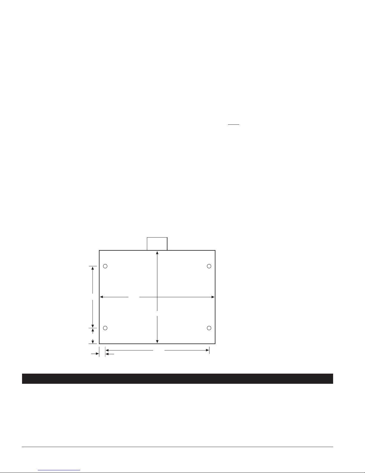
Four 5/16-inch holes are provided for mounting the TransTrack.
FIG. 6
HUB
Mounting Hole Detail
4"
1"
3/8"
7 1/2"
6"
6 3/4"
CONNECTION AND WIRING INSTRUCTIONS
1. Phase, Neutral, and Ground Connections
Phase, Neutral* and Ground: Following all applicable National Electrical Code standards as well as state and local codes,
connect the phase, neutral* and ground conductors from upstream overcurrent protection device to TransTrack. Ensure that
the conductor lengths are kept as short and straight as possible. On all high-leg delta systems, the Phase B conductor of the
suppressor (color-coded orange according to NEC) must be connected to the high-leg.
*DELTA-connected TransTrack does not have a neutral conductor.
6
TRANSTRACK™INSTALLATION, OPERATION AND MAINTENANCE MANUAL
Page 7
2. Connecting Form C Dry Contacts
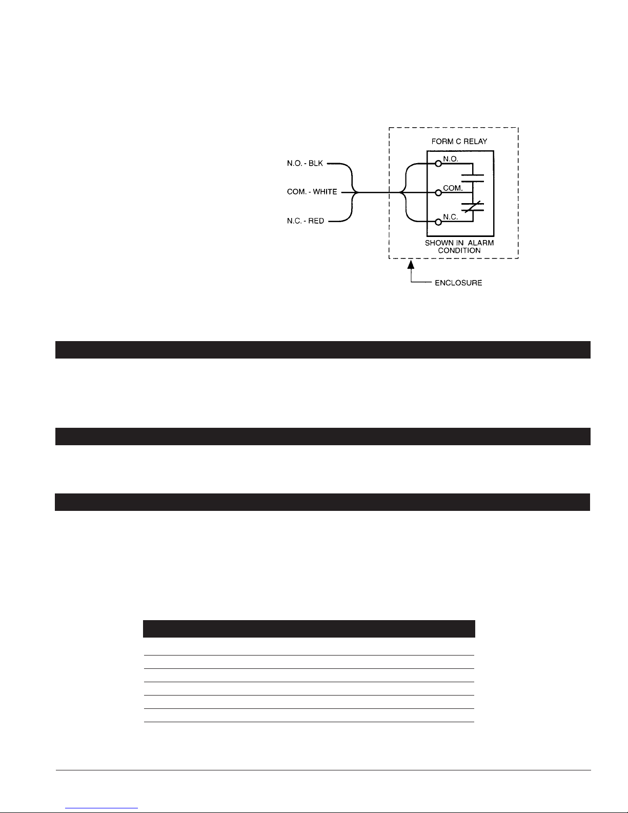
TransTrack units come standard with Form “C” dry contacts. The relay contacts are rated 110V DC/125V AC with maximum
switching power of 30W DC/62.5VA AC. Use butt splices within the panelboard to connect the Form “C” leads to the user’s
monitoring circuits. Alternatively, install a junction box between the TransTrack and the panelboard to connect Form “C”
leads to user’s monitoring circuits. If the Form “C” contacts are not used, user has the option of either cutting off the leads
or coiling up the leads and saving them for potential future use. Consult applicable local codes to ensure proper installation.
FIG. 7
Detail of Form “C” contacts
TRANSTRACK
3. Verification and Power Up
Apply power to TransTrack by closing the circuit breaker or molded-case switch feeding the suppressor. Verify that all “Phase
Protection Status” indicating lights are illuminated.
TROUBLESHOOTING
Call Joslyn Technical Support if you experience either of these conditions:
• Circuit breaker trips and cannot be reset
• One or more lights on TransTrack are not illuminated
* No user-serviceable parts inside.
TECHNICAL ASSISTANCE
Our staff is ready to support you and answer any questions.
Monday through Friday, 8:00 a.m. to 5:00 p.m. (EST) 800-647-1911.
RETURNS AND WARRANTY PROCEDURES
TransTrack products are warranted for a period of 25 years from date of purchase. In the event that any module or subassembly within the suppressor fails to perform as specified during the warranty period, call our Technical Support at 800-6471911 to obtain a Return Material Authorization number. We will immediately ship a replacement for the defective parts free
of charge (installation labor and site preparations excluded). Return the defective parts to Joslyn within 30 days of receiving
the replacement. Failure to return the defective parts will result in billing for the replacement parts. To help
expedite the return procedures, please have the following information at hand when you contact Joslyn:
INFORMATION EXAMPLE
Model Number TK-TT200-3Y208-F
Serial Number 23115-4103-001
Date of Purchase October 17, 2003 (41st week)
Sales Order Number 23115
Description of Failure Phase A light is off
Desired Action from Joslyn Replace
TRANSTRACK™INSTALLATION, OPERATION AND MAINTENANCE MANUAL
7
Page 8

WARRANTY STATEMENT
®
25 YEAR
WARRANTY
WARRANTY
25 YEAR
FREE
REPLACEMENT
During the applicable warranty period, any Total Protection Solutions™surge protector device which fails due to defect in
materials, workmanship, or any electrical anomaly, including lightning, shall be repaired or replaced at Joslyn’s discretion.
Prior to shipment of any suspect or known defective product to Joslyn a Return Material Authorization (RMA) number
must be obtained. An official Joslyn RMA number and shipping instructions can be obtained from the distributor where the
product was originally purchased. Distributors can obtain the official Joslyn RMA number by contacting the Joslyn Customer
Service Department at 800-647-1911. Products arriving at Joslyn without an official RMA number will not be accepted and
will be returned freight collect to the original point of shipment.
Products being returned with an official Joslyn RMA number should be shipped by prepaid freight to the nominated point of
return as shown on the RMA documentation.
The Company shall have no liability under this warranty for problems or defects directly or indirectly caused by misuse of the
Product, alteration of the Product (including removal of any warning labels), accidents, improper installation, application,
operation or improper repair of the Product.
THIS WARRANTY REPRESENTS THE ENTIRE WARRANTY OF THE COMPANY. ALL OTHER WARRANTIES EXPRESS OR
IMPLIED, ORAL OR WRITTEN, INCLUDING, BUT NOT LIMITED TO, THE WARRANTIES OF MERCHANTABILITY AND
FITNESS FOR A PARTICULAR PURPOSE ARE HEREBY DISCLAIMED.
THE LIABILITY OF THE COMPANY, AT ITS SOLE OPTION, UNDER THIS WARRANTY IS EXPRESSLY LIMITED TO THE
REPLACEMENT OR REPAIR OF THE DEFECTIVE PART THEREOF. IN NO EVENT SHALL THE COMPANY BE LIABLE OR
RESPONSIBLE FOR SPECIAL, INCIDENTAL, OR CONSEQUENTIAL DAMAGES OF ANY KIND OR CHARACTER, NOR
SHALL ITS LIABILITY EVER EXCEED THE PURCHASE PRICE PAID TO JOSLYN FOR SUCH DEFECTIVE PRODUCT.
This warranty is not transferable and may only be enforced by the original purchaser. Claims under this warranty must be
submitted to Joslyn within thirty (30) days of discovery of any suspected product defect.
arranty Period
W
TransTrack
™
25 Years from original date of purchase
©2006 PRINTED IN U.S.A. ALL RIGHTS RESERVED. PN 750-0091-001 REV 4 500/5.30.08/ J-2802
5900 Eastport Boulevard Richmond, VA 23231-4453 USA
TEL: 800.647.1911
www.tpsjoslyn.com
 Loading...