

Total Protection Solutions 300, 400, 200, ServiceTrack ST 080, ServiceTrack ST 160 Installation, Operation And Maintenance Manual
...Page 1
Surge
Protective
Devices
ServiceTrack ST Series:
080, 120, 160, 200, 240,
300 and 400
Installation,
Operation and
Maintenance
Manual
SERVICETRACK ST®INSTALLATION, OPERATION AND MAINTENANCE MANUAL
TEL: 800-853-8265 www.TPSCanada.ca
Page 2

TABLE OF CONTENTS
Before Installation
System Configuration Verification
Wiring Connection Diagrams
Upstream Over-Current Protection Device
Conductor Routing
Conductor Sizing
Conduit Openings
Mounting
Connection and Wiring Instructions
Phase, Neutral and Ground Connections
Connecting Form C Dry Contacts
Neutral to Ground Filter Jumper
Disconnect Switch Connections
Verification and Power Up
Troubleshooting
3 – 7
3
4
5
5
5
5 – 6
7
7 – 9
7
8
9
9
9
10
Technical Assistance
Standards and Listings
Returns and Warranty Procedures
Warranty Statement
10
10
10
11
2
SERVICETRACK ST®INSTALLATION, OPERATION AND MAINTENANCE MANUAL
Page 3
BEFORE INSTALLATION
WARNING: HAZARDOUS VOLTAGES PRESENT Improper installation or misapplication may result in
serious personnel injury and/or damage to electrical system. Read the complete installation instructions before
!
proceeding with installation. Remove all power to the electrical panel before installing or servicing the surge
protective device (SPD).
WARNING: Do not HIPOT the ServiceTrack ST unit or the electrical system that the ServiceTrack ST is con-
!
nected to without disconnecting the ServiceTrack ST conductors including phases, neutral and ground.
IMPORTANT SAFETY INSTRUCTIONS All work must be performed by licensed and qualified personnel. The electrical
system must be properly grounded in accordance with the U.S. National Electrical Code, state and local codes or other
applicable codes for this SPD to function properly. This device is suitable for installation where the available short circuit current is 200,000 rms symmetrical amperes at 600VAC or less.
1. System Configuration Verification
Confirm that the voltage(s) and service configuration shown on the ServiceTrack ST product label are consistent with the
voltage and service configuration of the facility. A model number is on the right side of the ServiceTrack ST unit. Each model
number corresponds to the configurations printed in the table below:
Example of a SPD model number: TK-ST240-3Y208-FLB
1
MODEL NUMBER
VOLTAGE VOLTAGE RANGE VOLTAGE RANGE
NOMINAL L-N L-L
CONFIGURATION
TK-STxxx-1P120 108-132 N/A
TK-STxxx-1P240 216-264 N/A
TK-STxxx-1S240 108-132 216-264
TK-STxxx-1S480 216-264 432-528
TK-STxxx-3Y208 108-132 187-229
TK-STxxx-3Y380
TK-STxxx-3Y400 207-253 360-440
TK-STxxx-3Y415 216-264 374-457
TK-STxxx-3Y480 249-305 432-528
TK-STxxx-3Y600 312-382 540-660
TK-STxxx-3D240 120/240
TK-STxxx-240NN N/A 216-264
TK-STxxx-380NN
TK-STxxx-480NN N/A 432-528
TK-STxxx-600NN 600 N/A 540-660
1
Suffixes shown at the end of model number denote available options
Option Suffixes
xxx Denotes surge rating per phase 080, 120, 160, 200, 240, 300, or 400
-B For surge counter
-DN For non-fused disconnect
-DF For fused disconnect
-F For enhanced transient filter
-L For component-level fusing
-N For non-fused only available for 080, 120, 160
-XX For NEMA 4X stainless steel enclosure
SERVICETRACK ST®INSTALLATION, OPERATION AND MAINTENANCE MANUAL
120
240
120/240
240/480
120/208
220/380
230/400
240/415
277/480
347/600
108-132
187-229 (B PHASE)
240
380
400
415 373-456
480
198-242
(A & C PHASES)
N/A
216-264
342-418
Notes: The power system operation frequency is between 47-63 HZ
Confirm that the environmental conditions are consistent with
the following ranges:
• Ambient Temperatures: -40° and +158° (-40° to 70°C)
• Relative Humidity: between 5% and 95%
• Altitude: less than 13,000 feet (4000 m)
342-418
360-440
Three-Phase WYE
Three-Phase WYE
Three-Phase WYE
Three-Phase WYE
Three-Phase WYE
Three-Phase WYE
Three-Phase high-leg DELTA
Three-Phase DELTA
Three-Phase DELTA
Three-Phase DELTA
Three-Phase DELTA
Single-Phase,
2-wire+ground
Single-Phase,
2-wire+ground
Split-Phase,
3-wire+ground
Split-Phase,
3-wire+ground
4-wire+ground
4-wire+ground
4-wire+ground
4-wire+ground
4-wire+ground
4-wire+ground
4-wire+ground
3-wire+ground
3-wire+ground
3-wire+ground
3-wire+ground
3
Page 4
WARNING: Check to ensure that a proper bond is installed between neutral and ground at the transformer
upstream from all 3-phase WYE, 3-phase high leg DELTA or split-phase ServiceTrack ST SPD (See NEC
!
2. Wiring Connection Diagrams
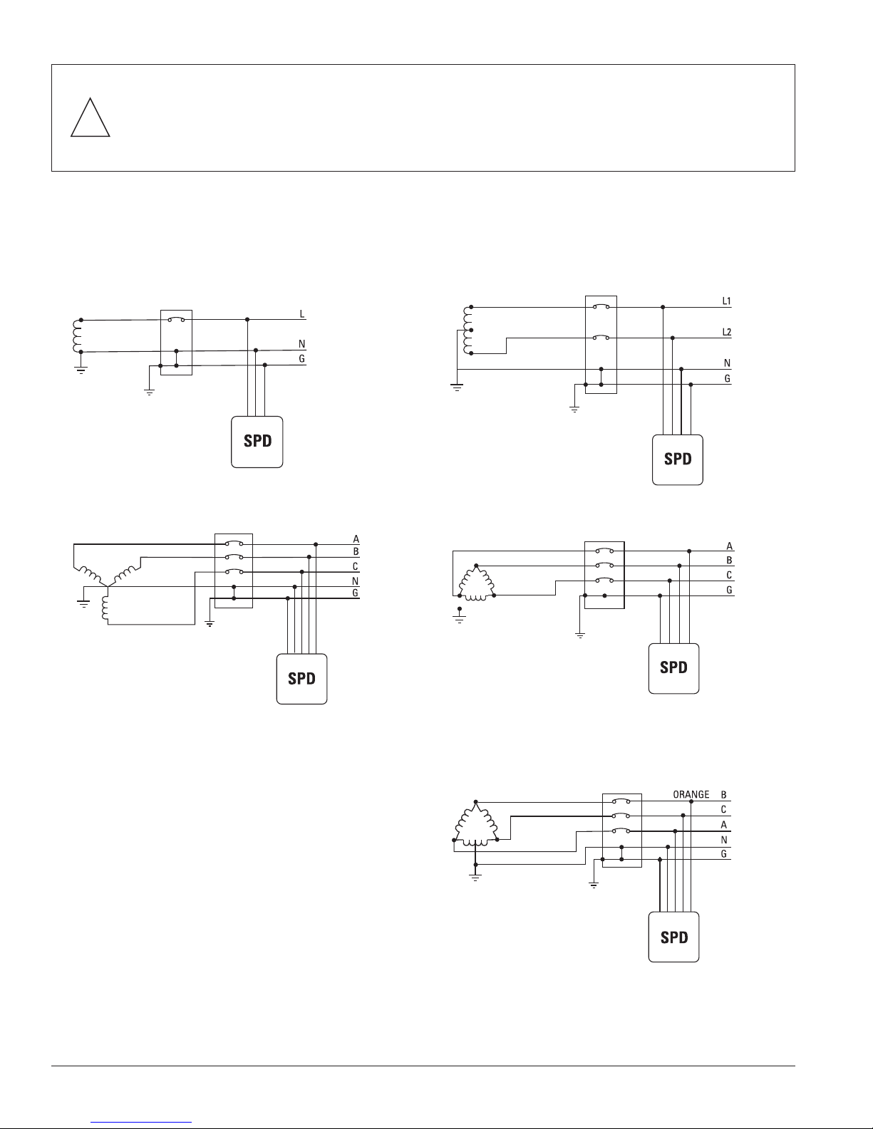
Figures 1-5 show the electrical relationship between ServiceTrack ST and these five basic service configurations: Single phase,
2 wire; Split phase, 3 wire; Three phase, 4 wire WYE; Three phase, 3 wire DELTA and Three phase, 4 wire high leg DELTA.
Fig. 1: Single Phase, 2-Wire Fig. 2: Split Phase, 3-Wire
Article 250). If the transformer is not accessible, check the main service disconnect/panel for the N-G bond.
Lack of a proper bond will damage ServiceTrack ST and void the warranty.
Connections to the SPD are clearly identified. For 80kA
models, connections are made via pigtail leads supplied with
the unit.
For 120kA to 400kA models, connections are made to
terminals inside the SPD enclosure. These terminals are
marked with labels.
For 3 phase units phase A is marked as “PHASE A”, phase B
is marked as “PHASE B” and phase C is marked as “PHASE
C”. For split phase units, the phase connections are marked
“Phase A” and “Phase B”. For single-phase units, the phase
connection is marked “Phase A”. Neutral (if applicable) is
marked as “Neutral Terminal” and ground is marked as
“Equipment Ground Terminal”.
Fig. 4: 3-Phase, 3-Wire DELTAFig. 3: 3-Phase, 4-Wire WYE
Fig. 5: 3-Phase, 4-Wire High-Leg DELTA
4
SERVICETRACK ST®INSTALLATION, OPERATION AND MAINTENANCE MANUAL
Page 5
3. Upstream Over-Current Protection Device
The ServiceTrack ST is listed as a Type 1 SPD per UL 1449 3rd Edition, suitable for use in both Type 1 and Type 2 SPD
applications. This means that the ServiceTrack ST can be installed on the line or load side of the main service disconnect.
ServiceTrack ST are one-port devices and must be connected in parallel to the electrical system.
• Optional Component-Level Fusing Units: Model Numbers With “-L” Suffix
(Example model number: TK-ST080-3Y208-FL)
The ServiceTrack ST units are listed as Type 1 SPDs making them suitable for use in Type 1 and Type 2 SPD
applications. These units DO NOT require an upstream over-current protection device and can be connected to
the electrical distribution system bus. They have built-in over-current fusing rated at 200,000 rms symmetrical
amperes at 600 VAC or less.
• Standard ServiceTrack ST Units: Model Numbers With “-N” Suffix - Type 2 SPD
(Example model number: TK-ST080-3Y208-NF)
These units MUST be connected to an upstream over-current protective device (circuit breaker, fuse or fused
switch). The ratings for the upstream over-current protective device are as follows:
For 80kA, 120kA and 160kA units:
Class J or equivalent fused disconnect or circuit breaker rated at 60 amperes maximum
for 80kA unit and 100 amperes maximum/600 volts maximum for 120kA and 160kA units.
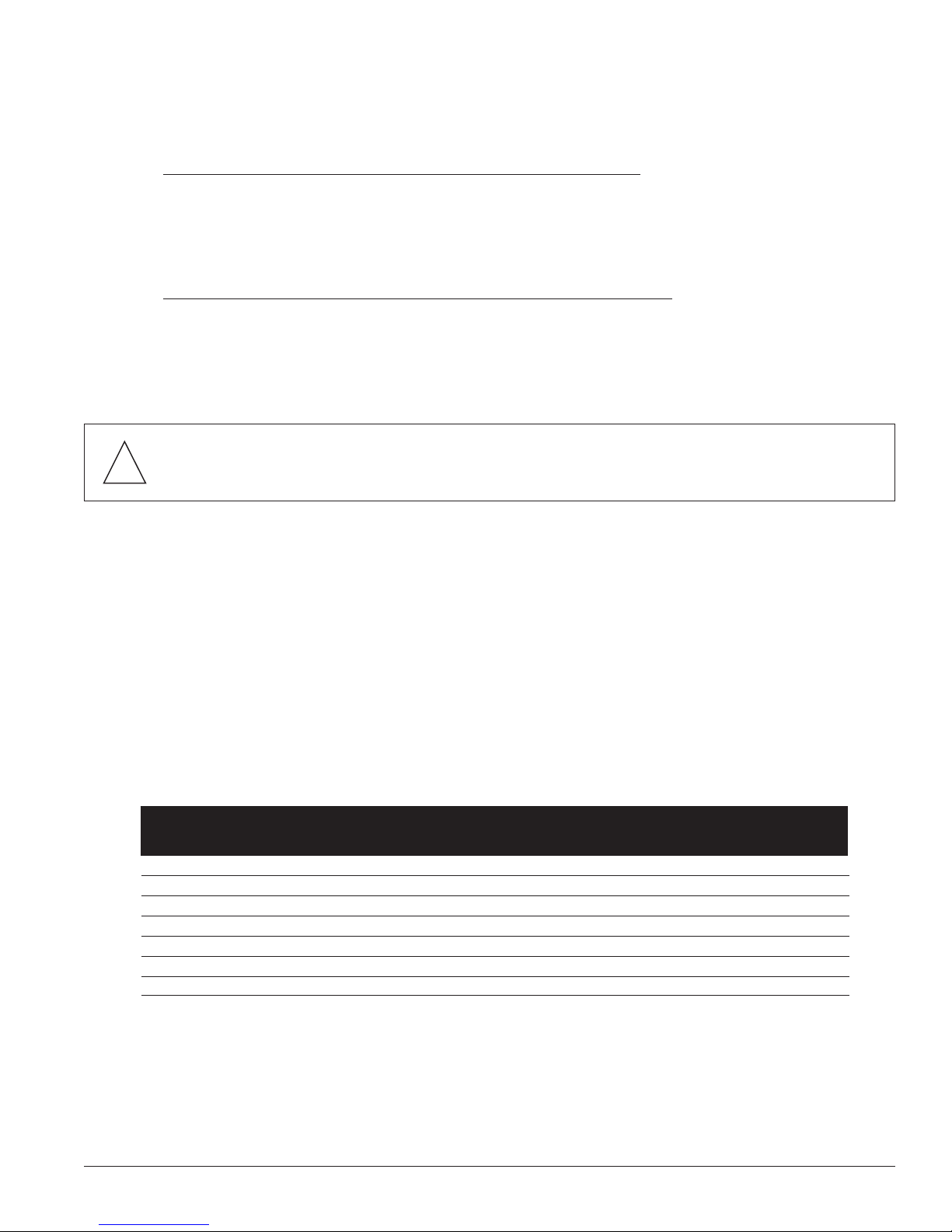
CAUTION: Do not splice ServiceTrack ST conductors within the unit’s enclosure or Manufacturer’s warranty
!
will be void. ServiceTrack ST’s performance will be limited severely if the conductors are (a) too long, (b) are
of too small a wire gauge, (c) have too many bends or (d) have sharp bends.
4. Conductor Routing
The factors listed above should be addressed during the design of an installation to reserve a suitable place for ServiceTrack ST
next to its point of connection to the electrical system. The selected mounting location should allow for the shortest possible
conductor runs and a direct route with a minimum of bends. If bends are required, they should be sweeping bends. Do not
make sharp 90° bends for appearance purposes because they will severely decrease the effectiveness of ServiceTrack ST.
Braiding or twisting conductors together using tie-wraps or electrical tape increases the protection performance of the device.
One or two twists or braids of all conductors per foot and securely tie-wrap when conductor lengths must exceed 12”.
5. Conductor Sizing
Total Protection Solutions recommends installing ServiceTrack ST by using the following conductor sizes for phase, ground
and neutral connections.
Example of a SPD model number: TK-ST240-3Y208-FL
PRODUCT LABEL SURGE CURRENT CONDUCTOR SIZE
DESIGNATION CAPABILITY RECOMMENDED MAXIMUM MINIMUM
TK-ST080-xxxxx 80kA/phase1 #10 AWG #10 AWG #10 AWG
TK-ST120-xxxxx 120kA/phase2 #6 AWG #2 AWG #10 AWG
TK-ST160-xxxxx 160kA/phase2 #6 AWG #2 AWG #10 AWG
TK-ST200-xxxxx 200kA/phase2 #4 AWG #2 AWG #10 AWG
TK-ST240-xxxxx 240kA/phase2 #4 AWG #2 AWG #10 AWG
TK-ST300-xxxxx 300kA/phase2 #4 AWG #2 AWG #10 AWG
TK-ST400-xxxxx 400kA/phase2 #4 AWG #2 AWG #10 AWG
1
conductor length.
2
80kA rated units are shipped with #10AWG leads. Note: Leads should be shortened during installation in order to minimize
For direct bus connection maximum wire size is recommended. Otherwise match wire size to the rating of the disconnect breaker.
SERVICETRACK ST®INSTALLATION, OPERATION AND MAINTENANCE MANUAL
5
Page 6
FRONT VIEW
RIGHT SIDE VIEW
CONDUIT FITTING HOLE
D
H
LEFT SIDE VIEW
M1
M2
C1
C2
C1
C2
C1
C3
TOP VIEW
SURGE RATING H
"A"
"A"
"A"
Ø
0.31 (7.9) TYP
OVERALL DIMENSIONS - IN (mm) MOUNTING HOLES
80, 120, 160kA 9.50 (241.3)
W
6.28 (159.5)D6.28 (159.5)M24.00 (101.6)
M1
3/4 (19.0)
A
3.00 (76.2)
C3C2
4.00 (101.6)
C1
TRADE SIZE PUNCH LOCATIONS
CONDUIT FITTING
8.75 (222.3)
ENCLOSURE BODYCOVER
4.38 (111.2)
6.00 (152.4)
240, 300, 400kA 8.28 (210.3)11.50 (292.1) 6.28 (159.5) 5.00 (127.0)1.00 (25.4)10.75 (273.1) 4.38 (111.2) 4.00 (101.6)
MOUNTING HOLES
4.00 (101.6)
6.00 (152.4)
10.00 (254.0)
9.50 (241.3)
11.50 (292.1)
15.50 (393.7)
200 to 400kA
80kA
SURGE RATING
12.28 (311.9)
8.28 (210.3) 6.28 (159.5)
6.28 (159.5)
OVERALL DIMENSIONS - IN (mm)
H
6.28 (159.5)W6.28 (159.5)
D M1
4.00 (101.6)
PUNCH LOCATIONS
CONDUIT FITTING
5.00 (127.0)
7.00 (177.8)
3/4 (19.0)
1.00 (25.4)
10.75 (273.1)
14.75 (374.6)
4.38 (111.2)
4.38 (111.2)
TRADE SIZE
3/4 (19.0)8.75 (222.3)
M2
A
4.38 (111.2)
C1 C2
4.00 (101.6)
6.00 (154.2)
3.00 (76.2)
C3
STANDARD UNITS
OPTIONAL COMPONENT LEVEL FUSING (-L)
120, 160kA
W
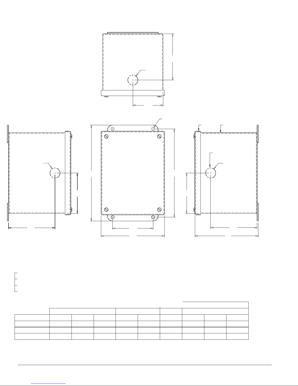
Fig. 6 Conduit Openings and
Enclosure/Mounting Dimensions
6.
1.00 (25.4)
1.25 (31.7)
6
SERVICETRACK ST®INSTALLATION, OPERATION AND MAINTENANCE MANUAL
Page 7
Conduit Openings
The 80kA unit comes with a 3/4” conduit hub. This hub requires a 1- 1/8” diameter hole for proper installation. The 120kA
to 160kA units come with a 1”conduit hub. This hub requires a 1-11/32” diameter hole for proper installation. The 200kA to
400kA units come with a 1.25” conduit hub. This hub requires a 1.75” diameter hole for proper installation.
Note the hub supplied with the unit, when properly installed, ensures the enclosure maintains its NEMA 4 rating.
All conduits and fittings must be rated and properly installed such that the final installation maintains a NEMA 4 rating.
Punch holes in locations indicated in Figure 6 for the conduit hub.
7. Mounting
ServiceTrack ST SPD
For convenience all units are shipped with a mounting kit consisting of a hub, chase nipple, offset nipple, lock washers
and wire bushing. Use the construction methods and hardware appropriate for your site. Install the conduit hub and other
supplied hardware. Install conductors according to sections 4, 5 and 6, herein. See Figure 6 for enclosure and mounting
dimensions.*
ServiceTrack ST Disconnect Switch Options
See the ServiceTrack ST Disconnect Switch Installation and Operations Manual for the proper mounting methods.
*Recommend avoiding wire-pulling lubricant due to potential for insulation deterioration, especially on such a short, small conductor installation.
8. Indoor vs. Outdoor Installations
NEMA 4 enclosures are suitable for indoor or outdoor use. NEMA 4X (stainless steel) enclosures are suitable for corrosive
environments as well. For direct sunlight applications, it is suggested to shade the unit. All conduits and fittings must be
rated and properly installed so that the final installation maintains the NEMA rating.
CONNECTION AND WIRING INSTRUCTIONS
1. Phase, Neutral, and Ground Connections
NOTE: In order to connect the ServiceTrack ST, the cover of the unit must be removed. Use care when removing the cover,
as there are wires, which run from components on the cover to inside the enclosure of the SPD. The monitor board (located
on the backside of the cover) has a cable harness which routes into the enclosure. Additionally there is a ground jumper
between the enclosure and the cover. Units supplied with a surge counter have a harness, which runs from the surge counter
display to a core inside the unit.
CAUTION: Prior to installation, ensure the system configuration and voltage is equivalent to the voltage
!
Following all applicable National Electrical Code standards as well as state and local codes, connect phase, neutral* and
ground to ServiceTrack ST. If suppressor is being installed on a breaker, installation electrician should install device directly
adjacent to the breaker feeding the device to insure conductor length is kept to a minimum. The 80ka is supplied with #10
AWG conductors permanently attached. Should mounting conditions require extension of the supplied conductor(s), installation electrician may use a butt-splice or parallel solder with shrink-tube installation. In no event shall the electrician use a
wire nut to make the extention as this will result in loss of suppressor’s performance. Ensure that the conductor lengths are
kept as short and straight as possible. The 120kA to 400kA units come with lugs that can be rotated to face in the direction of
the cable exit by loosening the nut on the input terminal lugs in the SPD. Tighten all lugs to 20in-lb (2.2Nm). On all highleg delta systems, the high-leg (color-coded orange according to NEC) must be connected to the Phase B of the SPD.
* The 3-wire plus ground Delta ServiceTrack ST does not have a neutral conductor.
rating of the ServiceTrack ST unit being installed. Do not splice ServiceTrack ST conductors within the unit’s
enclosure or Manufacturer’s warranty will be void.
SERVICETRACK ST®INSTALLATION, OPERATION AND MAINTENANCE MANUAL
7
Page 8
COVER REAR VIEW
Install SPD directly adjacent to the point of termination to insure conductor length is as short as possible
for optimum performance and protection.
2. Connecting Form C Dry Contacts
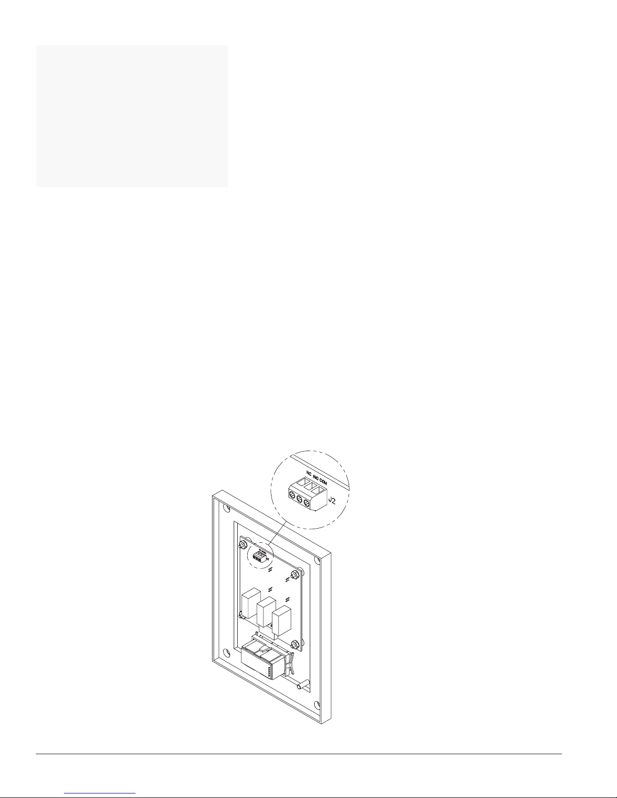
All ServiceTrack ST units come standard with one set of Form “C” dry relay contacts for the SPD status. These contacts are
for connection to a user-provided remote alarm and monitoring circuit. The relay contacts are rated 65VDC/150VAC with
maximum switching power of 30WDC/60VA AC. See Figure 7 for the form C contact configuration and terminal location on
the monitor board. The annotations on the diagram match the markings on the terminal block.
When input power is present on all phases, terminals “NO” and “COM” are an open circuit and terminals “NC” and “COM”
are a closed circuit. The contacts change state when the unit has encountered failure to one or more phases.
The installer must provide the appropriate raceway and wiring for the monitoring circuit, observing the restrictions and
conduit openings illustrated in an earlier section of this manual. The installer must route the monitoring conductors to the
terminal blocks on the door-mounted main monitoring board. Route the wires to allow the door to be opened and closed
properly. Tighten screws on terminals to 3.5 in-lbs (0.4 Nm). This terminal block will accept wire sizes #28AWG to #16AWG.
#18AWG to #20AWG is recommended.
Fig. 7 Remote Monitoring Terminal Block
Contacts shown in energized normal state.
(No fault condition)
8
SERVICETRACK ST®INSTALLATION, OPERATION AND MAINTENANCE MANUAL
Page 9
3. Neutral to Ground Filter Jumper
R
R
All ServiceTrack ST models with enhanced transient filter, “-F” suffix, (which have a neutral connection) come with a green
jumper wire, which loops out of the epoxy and connects the filter from neutral to ground. In certain medical applications or
circuits which employ or contain Ground Fault Circuit Interrupting protection, this Neutral to Ground filter connection
should be removed to avoid any nuisances that may trip the breaker.
WARNING: Prior to proceeding, ensure the SPD unit is fully disconnected and does not have voltage applied
!
to its input terminals.
Removal is accomplished by cutting the green jumper wire. Once cut, both ends should be properly separated and insulated
to prevent the ends from making inadvertent electrical contact.
4. Disconnect Switch Connections (-D option)
See the ServiceTrack ST Disconnect Switch Installation and Operations Manual for the proper connection methods.
5. Verification and Power Up
WARNING: It is recommended that the cover of the ServiceTrack ST unit along with its associated cabling be
!
installed prior to applying power. The monitoring harness, which exits the epoxy and connects to J2 on
the monitor board, contains line voltage when power is applied to the unit.
Apply power to ServiceTrack ST by closing the over current protection device or switch feeding the suppressor.
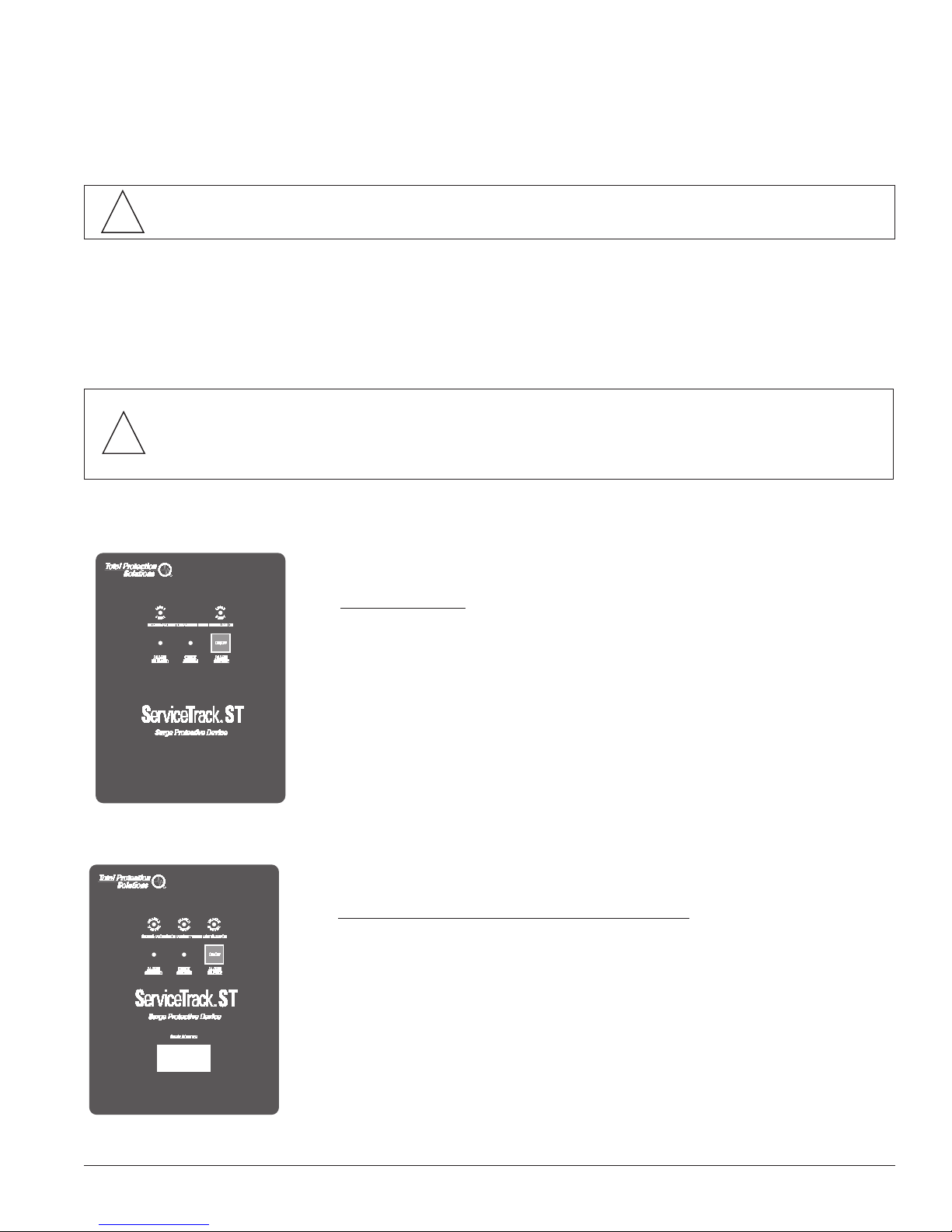
Fig. 8 Standard Monitoring
For Standard Units
Verify that all “Phase Protection Status” indicating lights are illuminated.
The “Check System” indicating light illuminates only upon failure of one or
more phases (indicating an alarm condition). Audible alarm should not
operate under normal conditions. The audible alarm can be "muted" by
pressing the “ALARM SILENCE” button, which subsequently will illuminate
the “ALARM SILENCED” light. Pressing the “ALARM SILENCE” button
again will enable the alarm.
Fig. 9 Surge Counter Option
For Units with Surge Counter Monitoring “-B” Option
The number of surges detected by the SPD is displayed on an eight-digit
LCD display on the front of the ServiceTrack ST door. The LCD counter
is battery backed to maintain the number of surges even during a power
loss. Press the button on the counter to reset the surge count.
SERVICETRACK ST®INSTALLATION, OPERATION AND MAINTENANCE MANUAL
9
Page 10

TROUBLESHOOTING
Your ServiceTrack ST system does not require scheduled maintenance. The unit’s heavy-duty construction is designed to
provide years of uninterrupted service. The unit contains no serviceable parts.
INDICATION PROCEDURE
One or more phase protection status indicating lights
are off, check system indicating light is on and form C
alarm contacts have changed state
Verify that the input power feeding ServiceTrack ST is
energized using a voltage tester. If power is present,
contact factory for assistance:
800-647-1911.
TECHNICAL ASSISTANCE
Our staff is ready to support you and answer any questions.
Monday through Friday, 8:00 a.m. to 5:00 p.m. (EST) at 800-647-1911
STANDARDS AND LISTINGS
• Listed by UL to UL 1449 3rd Edition (2009 Revision) for Type 1 and Type 2 SPD applications, cUL, and UL 1283
• Meets Requirements for UL 96A
• Compliant to IEEE C62.41.1-2002, C62.41.2-2002 and C62.45-2002
• NFPA 70 [NEC], Article 285
• RoHS Compliant
• CE, IEC 61643-11-2011
• EMC Directive 2004/108/EC
• Low Voltage Directive 2006/95/EC
RETURNS AND WARRANTY PROCEDURES
ServiceTrack ST products are warranted for a period of 30 years from date of purchase. In the event that any module or subassembly within the SPD fails to perform as specified during the warranty period, call our Technical Support at 800-647-1911
to obtain a Return Material Authorization number. We will immediately ship a replacement for the defective parts free of
charge (installation labor and site preparation excluded). Return the defective parts within 30 days of receiving the replacement. Failure to return the defective parts will result in billing for the replacement parts. To help expedite the return procedures, please have the following information at hand when you contact Total Protection Solutions:
INFORMATION EXAMPLE
Model Number TK-ST240-3Y208-FL
Serial Number 15478-0113-001
Date of Purchase January 2, 2013 (1st week)
Sales Order Number 15478
Description of Failure “Check System” indicating light illuminated
Desired Action Replace
10
SERVICETRACK ST®INSTALLATION, OPERATION AND MAINTENANCE MANUAL
Page 11

TPS WARRANTY STATEMENT
During the applicable warranty period, any Total Protection Solutions®surge protector device which fails due to defect in
materials, workmanship, or any transient surge event to include lightning, shall be repaired or replaced at the expense of the
manufacturer.
Prior to shipment of any suspect or known defective product a Return Material Authorization (RMA) number must be
obtained. An official RMA number and shipping instructions can be obtained from the distributor where the product was
originally purchased. Distributors can obtain the official RMA number by contacting the Total Protection Solutions Customer
Service Department at 800-647-1911 (in Canada 800-853-8265). Products arriving without an official RMA number will not be
accepted and will bereturned freight collect to the original point of shipment.
Products being returned with an official RMA number should be shipped by prepaid freight to the nominated point of return
as shown on the RMA documentation.
Total Protection Solutions shall have no liability under this warranty for problems or defects directly or indirectly caused by
misuse of the Product, alteration of the Product (including removal of any warning labels), accidents, improper installation,
application, operation or improper repair of the Product.
THIS WARRANTY REPRESENTS THE ENTIRE WARRANTY OF TOTAL PROTECTION SOLUTIONS. ALL OTHER
WARRANTIES EXPRESS OR IMPLIED, ORAL OR WRITTEN, INCLUDING, BUT NOT LIMITED TO, THE WARRANTIES OF
MERCHANTABILITY AND FITNESS FOR A PARTICULAR PURPOSE ARE HEREBY DISCLAIMED. THE LIABILITY OF TOTAL
PROTECTION SOLUTIONS, AT ITS SOLE OPTION, UNDER THIS WARRANTY IS EXPRESSLY LIMITED TO THE REPLACEMENT OR REPAIR OF THE DEFECTIVE PART THEREOF. IN NO EVENT SHALL TOTAL PROTECTION SOLUTIONS BE
LIABLE OR RESPONSIBLE FOR SPECIAL, INCIDENTAL, OR CONSEQUENTIAL DAMAGES OF ANY KIND OR CHARACTER,
NOR SHALL ITS LIABILITY EVER EXCEED THE PURCHASE PRICE PAID FOR SUCH DEFECTIVE PRODUCT.
Warranty period begins from date of original owner purchase. This warranty is not transferable and may only be enforced by
the original end user. Claims under this warranty must be submitted to Total Protection Solutions within thirty (30) days of
discovery of any suspected product defect.
Warranty Period
ServiceTrack®ST 30 years
F RE E
R EP LA CE ME NT
30 YEAR
W A RR A N T Y
W A RR A N T Y
30 YEAR
SERVICETRACK ST®INSTALLATION, OPERATION AND MAINTENANCE MANUAL
11
Page 12

30 YEAR
W A RR A N T Y
W A RR A N T Y
30 YEAR
F RE E
R EP LA CE ME NT
®
©2014 TOTAL PROTECTION SOLUTIONS, LLC PRINTED IN USA ALL RIGHTS RESERVED PN 750-0092-001 A09 062414
TEL: 800-853-8265 www.TPSCanada.ca
 Loading...