

Page 1
Advanced Cable Tester v2 User Manual
The Advanced Cable Tester v2 (ACT v2) provides an easy-touse web interface that allows for remote operation and logging.
The ACT v2 can be operated over USB or over Ethernet. The
ACT v2 can also be configured to operate in a stand-alone
mode that does not require a host PC. The tester provides audio
and visual pass/fail indicators for qualification of cables without
the need for the graphical interface.
Designed to be modular and flexible, the ACT v2 has
replaceable modules that are designed to support specific types
of cables. The following cable types are currently supported and
more cables will be included in the future:
• USB Type-C to USB Type-C
• USB Type-C to USB 3.1 Standard-A
• USB Type-C to USB 3.1 Standard-B
• USB Type-C to USB 3.1 Micro-B
• USB 3.1 Standard-A to USB 3.1 Standard-B
• USB 3.1 Standard-A to USB 3.1 Micro-B
• USB Type-C to MFi Lightning
• USB 3.1 Standard-A to MFi Lightning
• HDMI Type A to HDMI Type A
Advanced Cable Tester v2
User Manual v2.0.0
May 17, 2019
A complete battery of tests is performed when a cable is
plugged in. These test include:
• Continuity/Wiring - cable specific and customizable
• DC Resistance - pin and wire measurements, Rd, Rp, Ra,
and more
• Signal Integrity - configurable from 518 MHz to 12.8 GHz on
up to 5 differential pairs
• E-Marker Verification - PD2/PD3 verification, Quiescent
Current
• Apple MFi Mandated Tests - Over Voltage Protection,
Quiescent Current, Source Measurement Unit Tests
Page 2
Advanced Cable Tester v2 User Manual v2.0.0
1 Quick Start Guide
The Advanced Cable Tester v2 was designed with the factory in mind. Once a valid cable
connector module is installed and the user has selected a valid test profile, the tester is
configured and ready to test. As soon as a cable is inserted, the tests defined in the test
profile will start.
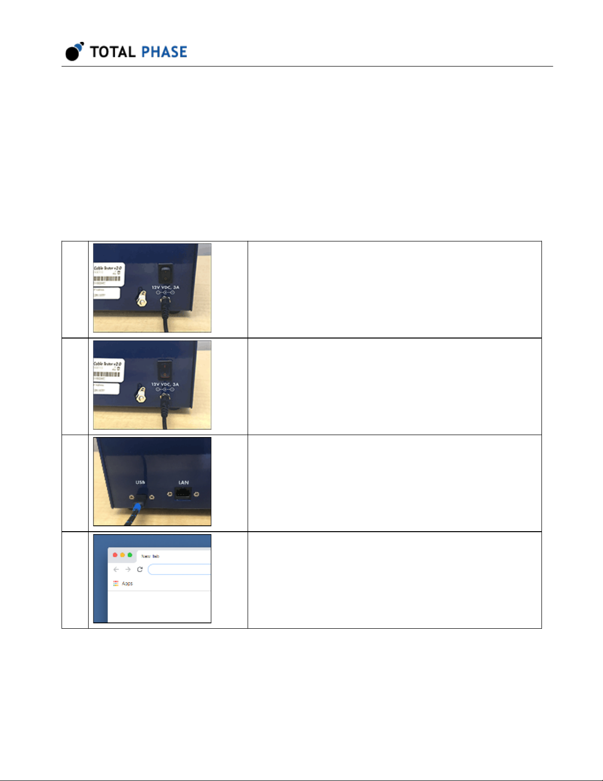
These are the steps to get started:
1 Connect the ACT v2 tester to the included power adapter
and plug it into a power source.
For optimal performance, the tester should be connected to
ground using the Ground Lug.
2
3 Connect a USB cable from the ACT v2 USB port to a local
4 Open a Mozilla Firefox or Google Chrome web browser
Turn on the power switch to boot the tester.
computer.
The ACT v2 tester uses the RNDIS driver. Please see
Connectivity for more information.
window.
2
Page 3
Advanced Cable Tester v2 User Manual v2.0.0
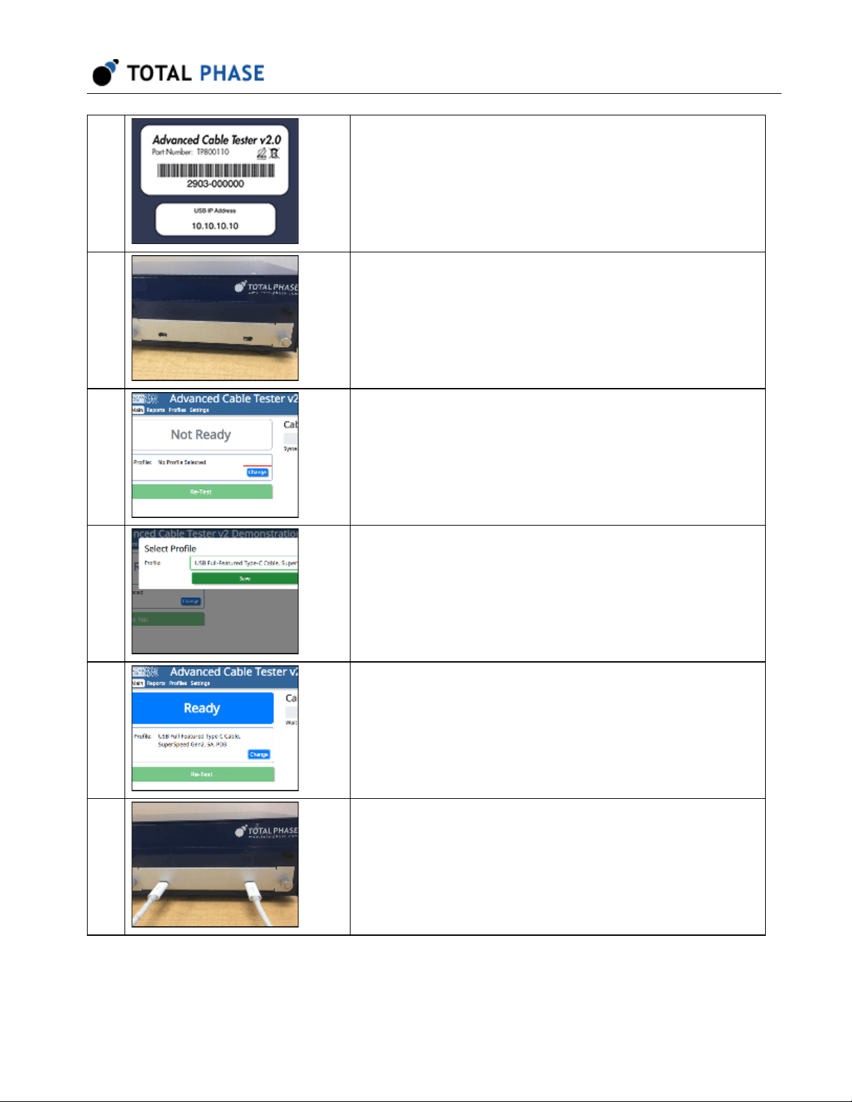
5 Enter the USB IP address from the product label on the
back of the ACT v2 tester. This will take you to the main
web application interface.
6 Install a cable connector module into the module bay of the
ACT v2 tester. Once installed, the module information will
be displayed in the web application.
7 Configure the tester, Click on the Change button to open a
dialog window to show the available test profiles.
8 Select the desired profile (and enter any tag information as
required) and click Save.
9 The tester is now ready to test cables.
10 Insert a cable into the connector modules. When the cable
is detected, the tests will start. A progress bar on the LCD
screen and in the web application provide feedback.
3
Page 4
Advanced Cable Tester v2 User Manual v2.0.0
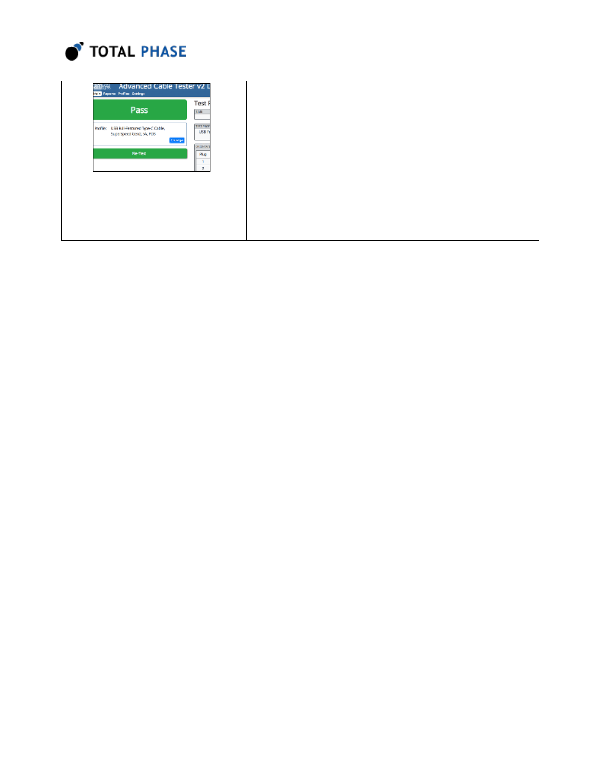
11 Once the tests complete, the cable will either Pass or Fail
the test requirements. The appropriate state will be
displayed on the LCD screen and the web application.
To re-test the same cable, click the Re-Test button in the
web application.
To test another cable, simply replace the cable in the tester.
When the new cable insertion is detected, the test
sequence will start.
4
Page 5

2 General Overview
2.1 Revision History
2.1.1 Release 2.00
This release provides support for the new v2.0 hardware architecture and modular
connector interface. All tests and the display of their results have been improved.
2.2 General Description
Combining blazing fast performance with a low cost per test and a rugged design, the
Advanced Cable Tester v2 enables rapid spot-checking of cables, easy-to-understand
reports, with 100% test coverage for lab and production environments at a fraction of the
price, time, and labor versus other solutions. Whether your application is 100% quality
control in a factory or statistical process control in a laboratory, the Advanced Cable
Tester v2 will provide high precision and accuracy with thorough test coverage, without
expensive scopes, custom fixtures, or highly trained personnel, saving hundreds of
thousands of dollars.
Advanced Cable Tester v2 User Manual v2.0.0
This document describes the Advanced Cable Tester v2 web software applications, the
Advanced Cable Tester v2 Hardware and how to use both.
Figure 1 : Advanced Cable Tester v2 Hardware
Designed to be modular and flexible, the Advanced Cable Tester v2 has replaceable
modules that are designed to support specific types of cables. Table 1 lists all the cable
connector modules that are available for testing with the ACT v2:
Table 1 : ACT v2 Connector Modules
5
Page 6

Advanced Cable Tester v2 User Manual v2.0.0
Part Number ACT v2 Connector Module
TP820110 USB Type-C to USB Type-C
TP820210 USB 3.1 Standard-A to USB Type-C
TP820310 USB Type-C to USB 3.1 Micro-B
TP820410 USB 3.1 Standard-A to USB 3.1 Micro-B
TP820510 USB 3.1 Standard-A to USB 3.1 Standard-B
TP820610 USB Type-C to USB 3.1 Standard-B
TP821010 HDMI Type A to HDMI Type A
TP823010 USB 3.1 Standard-A to MFi Lightning USB2
TP823110 USB Type-C to MFi Lightning USB2
The Advanced Cable Tester v2 is able to support custom cable connectors. Please
contact Total Phase Sales for more details about our custom cable program.
A complete battery of tests is performed when a cable is plugged in. These tests include:
• Continuity/Wiring - cable specific and customizable
• DC Resistance - pin and wire measurements, Rd, Rp, Ra, and more
• Signal Integrity - configurable from 518 MHz to 12.8 GHz on up to 5 differential
pairs
• E-Marker Verification - PD2/PD3 verification
• Apple MFi Mandated Tests
- Over Voltage Protection, Quiescent Current, Source Measurement Unit Tests
The Advanced Cable Tester v2 can be operated with or without a computer or tablet. The
tester provides clear audio and visual feedback to test operators to indicate whether DUT
passed or failed for fast processing.
Continuity testing checks all pins for continuity, preventing dangerous situations like
shorts of VBUS to data signals, VBUS/GND reversal, etc., which could damage devices.
DC Resistance ("DCR") and IR Drop testing confirms that each power pin (VBUS and
GND) is capable of carrying the required current to meet the applicable specification. For
Type-C cables, each power pin is individually measured, then the cable as a whole is
tested.
6
Page 7

Advanced Cable Tester v2 User Manual v2.0.0
E-Marker testing reads the data from all E-Markers present on the cable, then validates
the advertised data and power capabilities against the actual measured parameters of
the cable. Additionally, the values of fields such as Vendor ID, Product ID, Test ID,
firmware and hardware versions can be specified by the operator, for easy pass/fail
determination of cables through a QA process.
Lightning testing ensures proper operation of the Lightning plug, including proper
Lighting plug power-up, over-voltage, recovery, quiescent current, and current limit
testing per the Apple MFi specification. The ACT v2 tester is the only tester available that
can perform the tests required by the Apple Accessory Interface Specification (R31 and
greater).
7
Page 8
3 Device Specifications
3.1 Hardware Specifications
Advanced Cable Tester v2 User Manual v2.0.0
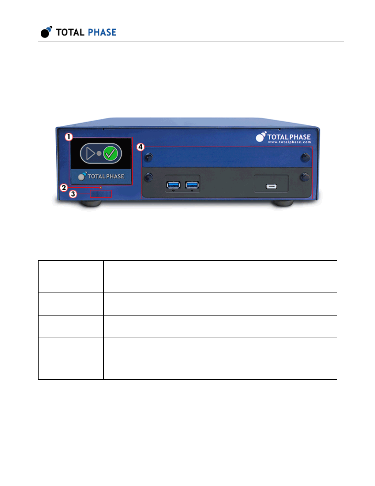
Figure 2 : Advanced Cable Tester v2 Hardware
Table 2 : Advanced Cable Tester v2 - Front
1 Screen LCD screen provides pass/fail and progress information. Please see
Standalone Operation Overview for more information about how to use the
ACT v2 in standalone mode.
2 Power Green LED indicates that the unit is powered on.
Red LED indicates a power-related system fault.
3 Speaker Speaker provides audio pass/fail indicator. The volume of the speaker can
be set in the web application
4 Module Bay The ACT v2 is designed to support replaceable connector modules.
Connector modules can be full-height or half-height. When using half-height
connector modules, a separate plate must be secured to the module bay to
prevent accidental intrusions into the chassis.
8
Page 9
Advanced Cable Tester v2 User Manual v2.0.0
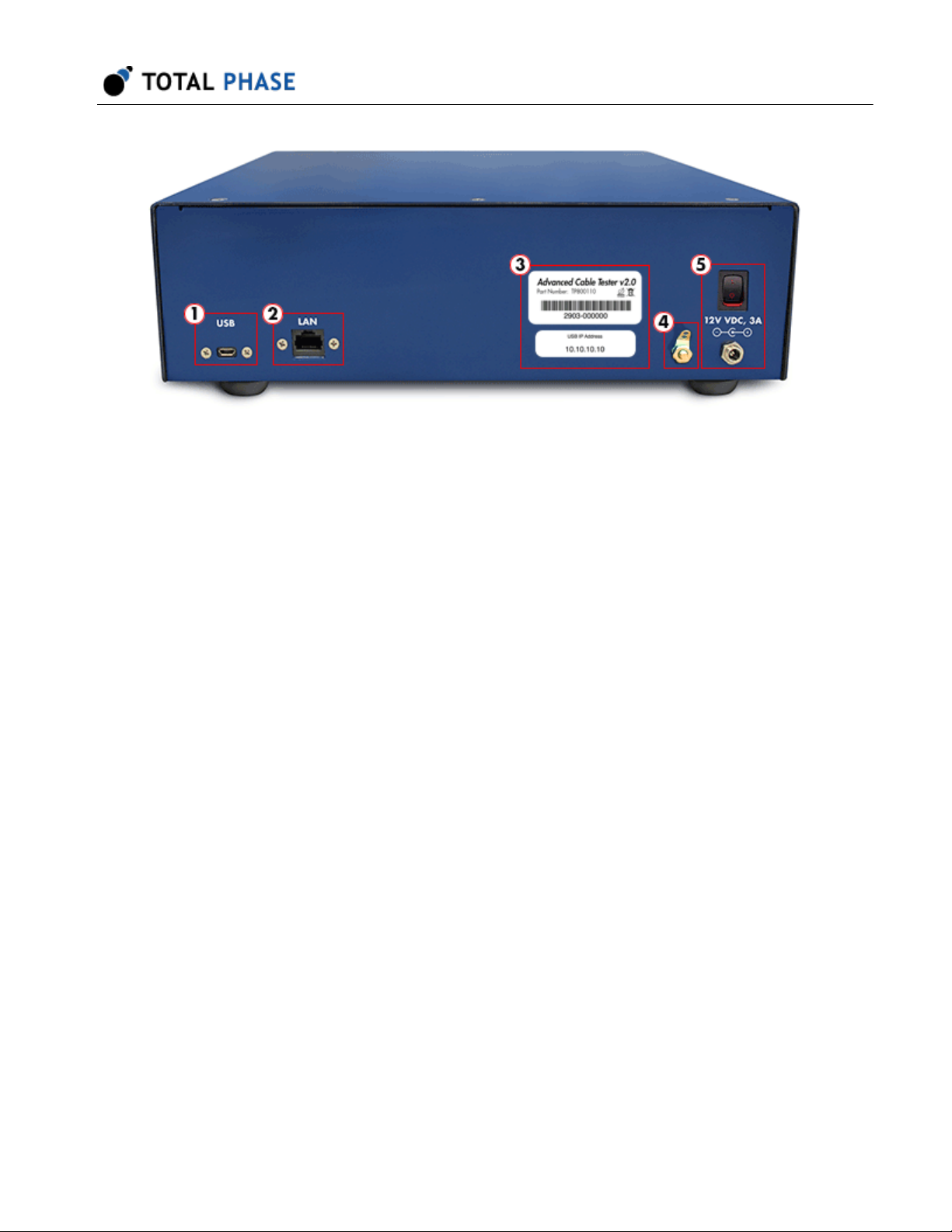
Figure 3 : Advanced Cable Tester v2 Hardware - Back
Table 3 : Advanced Cable Tester v2 - Back
9
Page 10
Advanced Cable Tester v2 User Manual v2.0.0
1 USB The ACT v2 can be accessed locally via USB. All firmware updates
must be performed via the USB port. Please see Connectivity for
details.
2 LAN The ACT v2 can be accessed remotely via Ethernet. Please see
Connectivity for information about how to connect to the ACT v2.
3 Product Labels The serial number for the ACT v2 tester and the controller are provided
on these labels. The Controller serial number label provides the default
USB IP address used to access the web application and the system
management application.
4 Ground Lug For optimal performance, the ACT v2 tester should be connected to
ground using the Ground Lug. A grounding tab is provided that can be
soldered to a ground wire. Simply unscrew the nut to get access to the
grounding tab.
5 Power The ACT v2 tester must be powered with the provided power adapter to
ensure the correct voltage and current levels to reliably run the cable
tests.
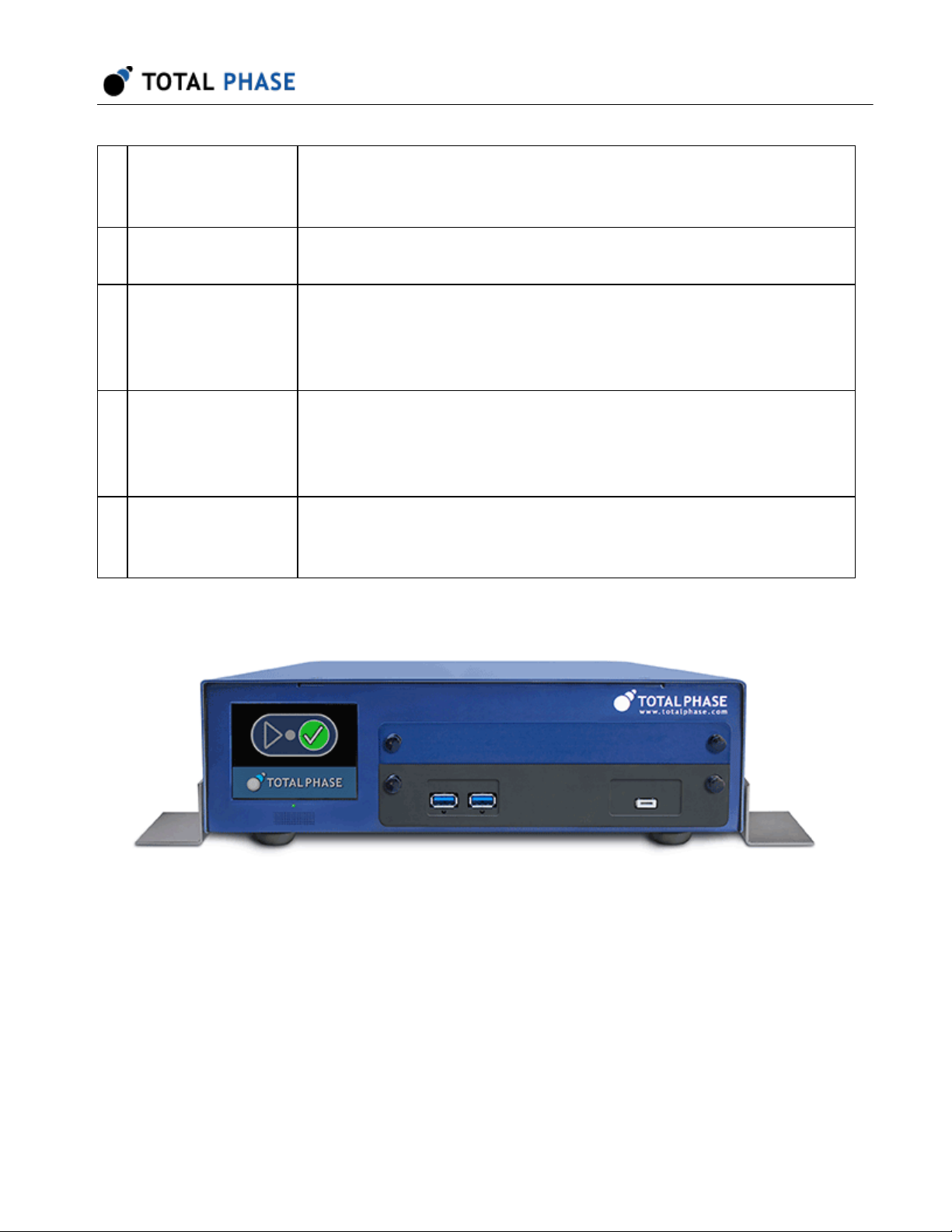
3.1.1 Securing the ACT v2 to a Work Surface
Figure 4 : Advanced Cable Tester v2 Hardware with
brackets installed.
Optional mounting brackets can be installed on the ACT v2 tester so that it can be
secured to a work surface. To install the brackets, simply remove the screws as shown in
the diagram below. The bracket can then be attached to the ACT v2 with the provided
screws.
10
Page 11

3.2 Software Specifications
• The web interface requires the latest version of Mozilla Firefox or Google Chrome
web browser
• Test Profiles: Held in non-volatile storage on the Promira platform
• Test Results: Up to 1 million test results are stored in a circular buffer in nonvolatile storage.
3.3 Physical Specifications
• Power Supply: 100-240V 50/60Hz AC - adapter included
• Dimensions: W x D x L: 30.5 x 27.3 x 10.2 cm (12.0 x 10.8 x 4.0 in)
Advanced Cable Tester v2 User Manual v2.0.0
• Weight: 3.8 kg (8.4 lbs)
• Operating Temperature: 10° to 35° C (50° to 95° F) non-condensing
11
Page 12

Advanced Cable Tester v2 User Manual v2.0.0
4 Advanced Cable Tester v2 Hardware
4.1 General Operation
The Advanced Cable Tester v2 was designed with the factory in mind. Once a valid cable
connector module is installed and the user has selected a valid test profile, the tester is
configured and ready to test. As soon as a cable is inserted, the tests defined in the test
profile will start. Once the test is complete, the pass/fail status is displayed on the LCD
screen on in the web application. As soon as the cable is removed, the tester is ready to
test the next cable.
4.1.1 Test Limits
To ensure consistent and reliable test results, connector modules are designed to have a
limited lifespan. The number of tests that can be performed on a connector module is
hard-coded into the module. As the number of tests approaches this limit, the operator
will be warned. Once the limit has been reached, no additional tests can be performed
on that connector module. At that point, the connector module will need to be replaced to
continue testing.
Similarly, the ACT v2 hardware itself also has a hardware limit on the number of times a
connector module can be installed before the connector is worn. As the number of
module insertions approaches this limit, the operator will be warned. Once the limit has
been reached, the ACT v2 tester will need to be serviced.
4.2 Connectivity
Communication between the end user platform and the ACT v2 is via TCP/IP over
Ethernet-over-USB or via TCP/IP over Ethernet. No additional device drivers are required
for using either method.
4.2.1 USB
The Advanced Cable Tester v2 uses Ethernet over USB. To use this interface, connect
the device to your PC with a USB cable and follow the instructions below to set up the
connection on the PC.
The Ethernet over USB connection is established using the RNDIS or ECM protocol. In
this case, the ACT v2 will act as a DHCP server and provide an IP address to your
12
Page 13
Advanced Cable Tester v2 User Manual v2.0.0
computer or tablet in the 10.0.0.0/24 range. The IP address of the USB interface can be
found on the labels on the back of the device.
Windows
1. Connect ACT v2 to PC with USB cable.
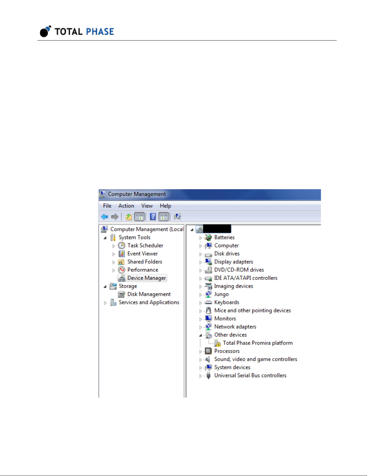
2. After the tester is connected to the PC, Windows will automatically search for the
appropriate RNDIS driver. To verify the drive is installed correctly, right-click on
Computer and select Manage. From System Tools, select Device Manager. If
the ACT v2 shows up with an exclamation mark, continue to the next step and
install the driver.
13
Page 14
Advanced Cable Tester v2 User Manual v2.0.0
Otherwise, close this window, skip RNDIS driver installation in the next step and
continue to the following step.
3. Install RNDIS driver:
a. Right-click on Total Phase Platformdevice and select Update Driver
Software... When prompted to choose how to search for device driver
software, choose Browse my computer for driver software.
b. Browse for driver software on your computer will come up. Select Let me
pick from a list of device drivers on my computer.
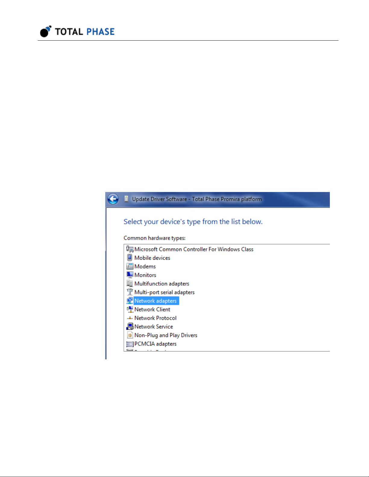
c. A window will come up asking to select the device type. Select Network
adapters, as RNDIS emulates a network connection.
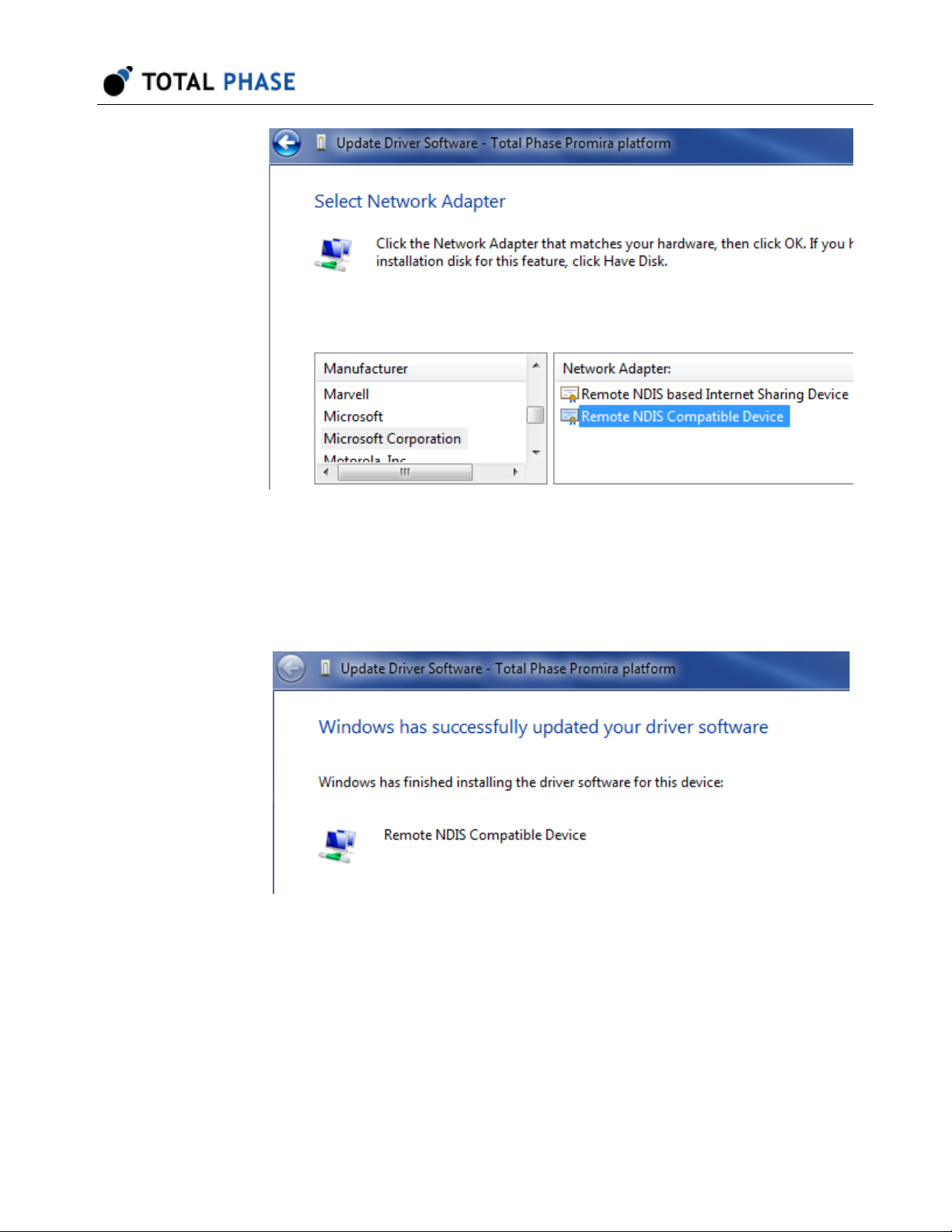
d. In the Select Network Adapter window, select Microsoft Corporation from
the Manufacturer list. Under the list of Network Adapter:, select Remote
NDIS compatible device.
14
Page 15
Advanced Cable Tester v2 User Manual v2.0.0
e. The Total Phase ACT v2 device is now installed and ready for use.
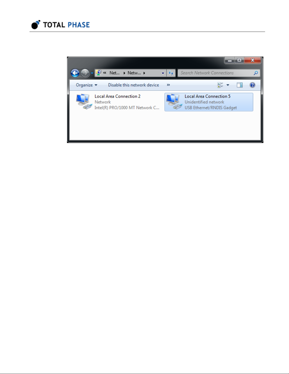
4. From the Start menu, select Control Panel | Network and Internet | Network
and Sharing Center.
5. Select Change adapter settings on the left panel.
6. Right-click on the USB Ethernet/RNDIS Gadget adapter, select Properties.
15
Page 16
Advanced Cable Tester v2 User Manual v2.0.0
Figure 5 : Windows Change adapter settings
window.
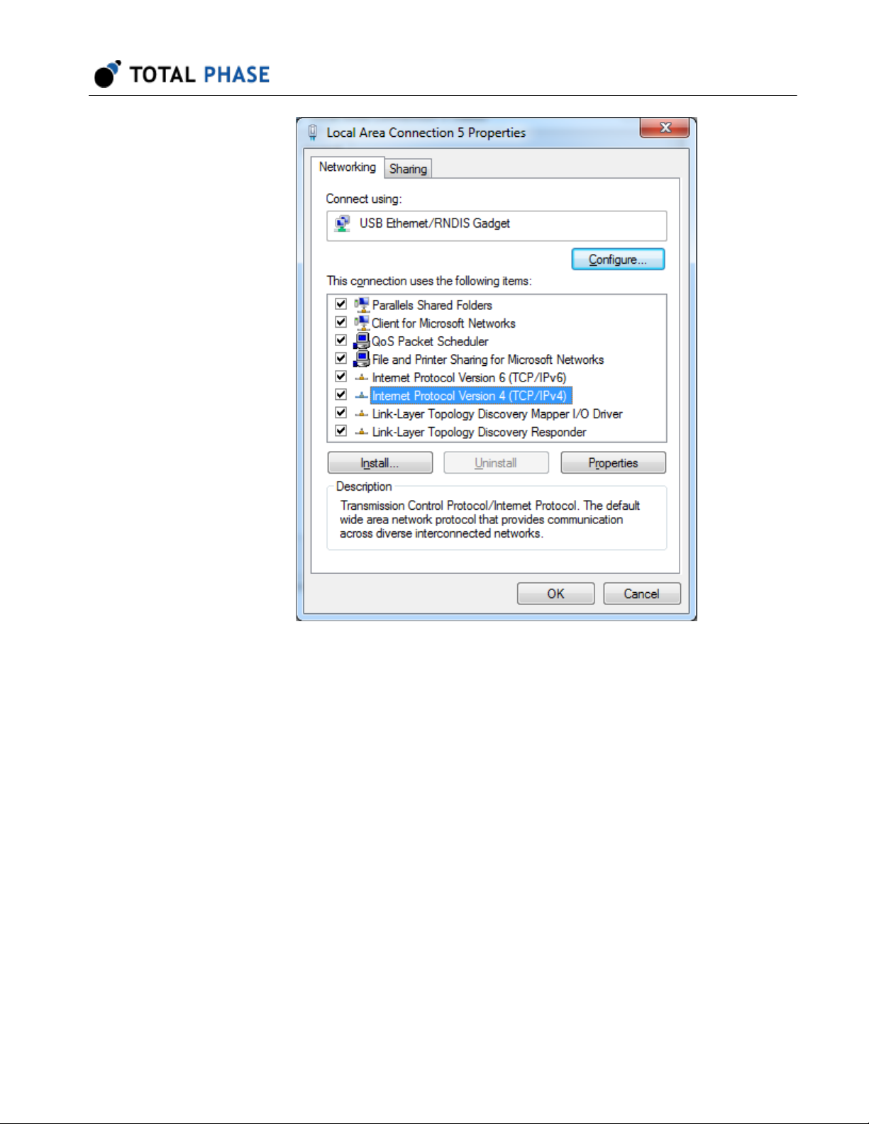
7. Double click on Internet Protocol Version 4 (IPv4).
16
Page 17
Advanced Cable Tester v2 User Manual v2.0.0
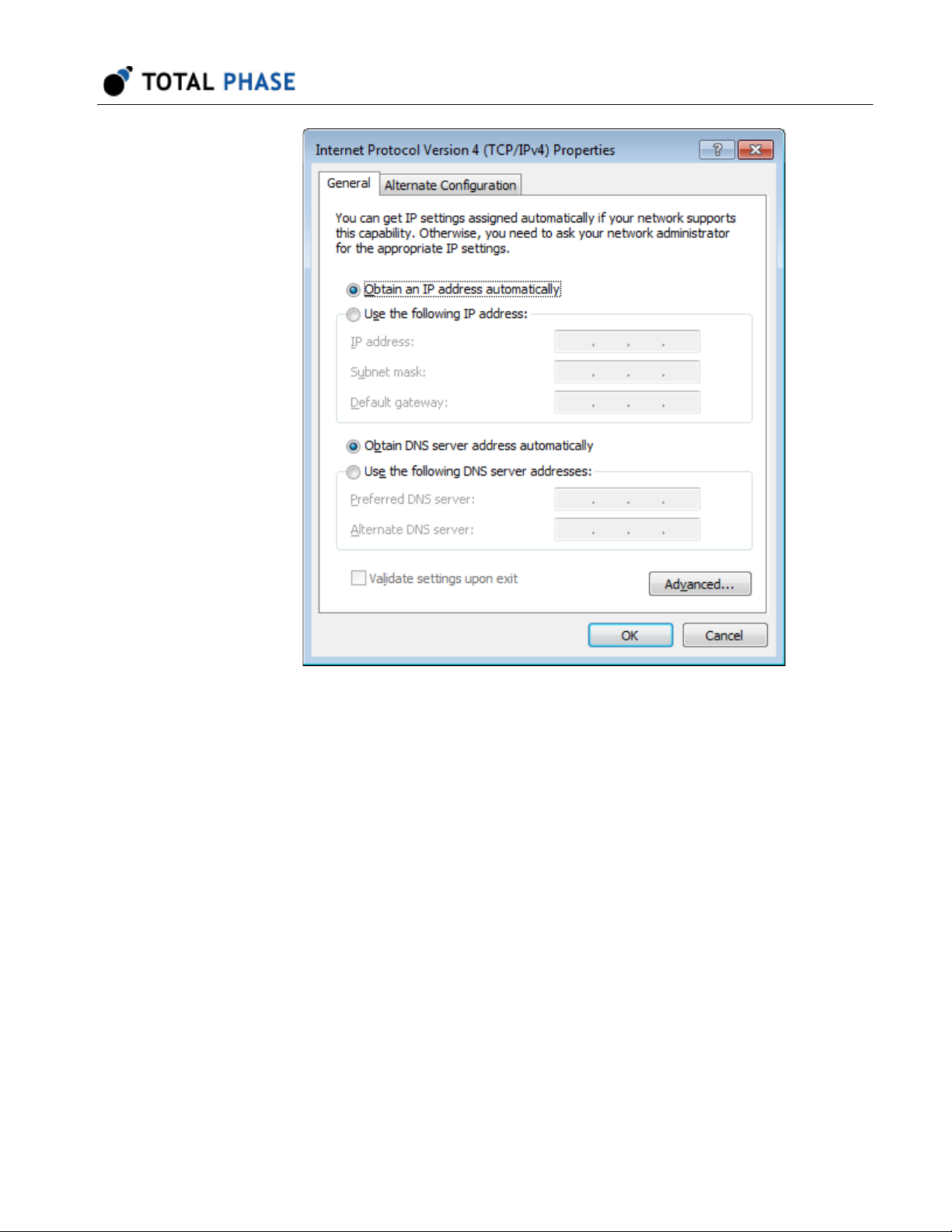
Figure 6 : Windows Network Interface Properties
dialog.
8. Select Obtain IP address automatically and also select Obtain DNS server
address automatically.
17
Page 18
Advanced Cable Tester v2 User Manual v2.0.0
Figure 7 : Windows IPv4 Properties dialog.
9. Select OK and Close to dismiss the dialogs.
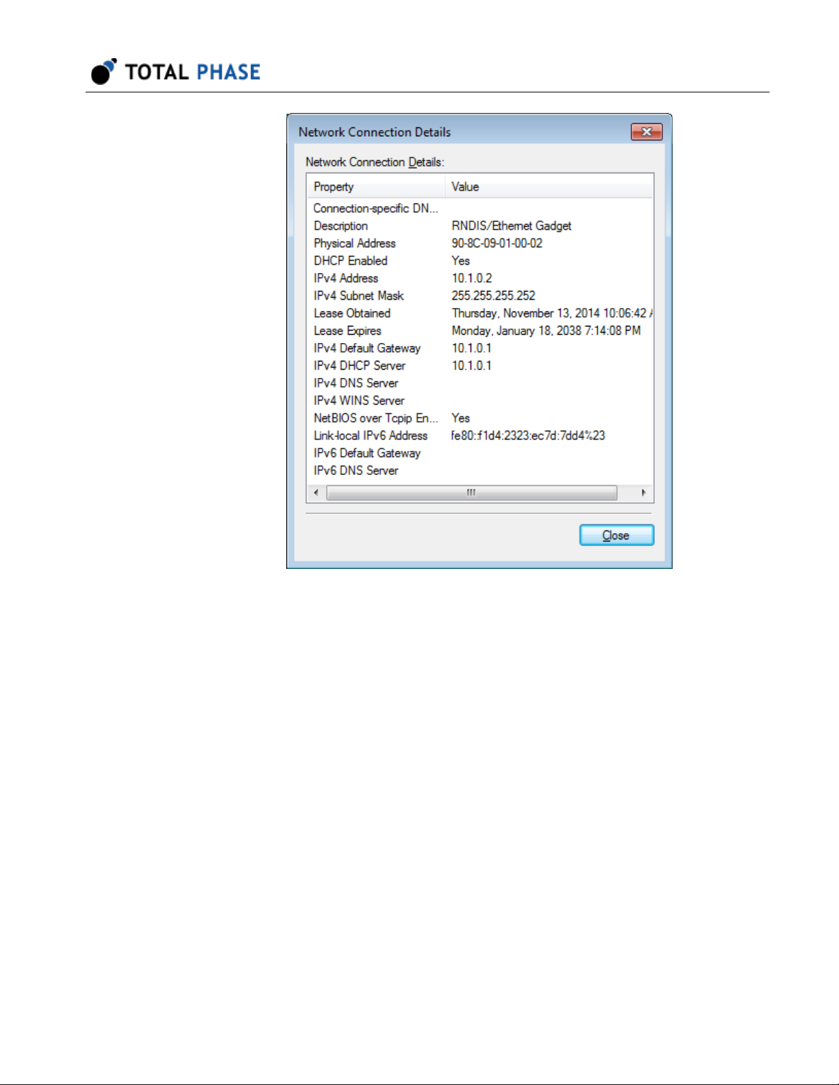
10. In order to make sure it is ready or to know the IP address of the Advanced Cable
Tester v2, right-click on the USB Ethernet/RNDIS Gadget adapter, select Status
and then select Details.... The IP address assigned to the network interface on
the host PC is will be in the format of 10.x.x.x and is listed as the IPv4 Address.
The IP address of the device will be at the preceding address. For example, the
image below shows 10.1.0.2 for the host IP address. The device address will then
be 10.1.0.1. This device address will also be displayed in the Control Center
software and will be needed when connecting to the device using the API.
18
Page 19
Advanced Cable Tester v2 User Manual v2.0.0
Linux
Figure 8 : Windows Connection Details.
11. Select OK and Close to dismiss the dialogs.
1. Connect ACT v2 to PC with USB cable.
2. Use ifconfig -a to determine the network interface of ACT v2. If you do not
recognize which one is the new interface, compare the lists from ifconfig -a
before and after plugging in the device.
19
Page 20

3. The Advanced Cable Tester v2 will be shown as tppx.
Mac OS X
1. Connect ACT v2 to PC with USB cable.
2. Select Network under System Preferences.
3. Select Total Phase Platform
Advanced Cable Tester v2 User Manual v2.0.0
Figure 9 : Mac OS X Network Preferences
window.
4. Select Using DHCP from the Configure IPv4: dropdown list box.
20
Page 21

5. Select Apply to apply the changes.
4.2.2 Ethernet
The ACT v2 can be connected to through the Ethernet port. The ACT v2 can be
configured to static IP addressing or dynamic IP addressing (DHCP). The default
network preferences of the ACT v2 for Ethernet is a static address and its IP address is
192.168.11.1. The network preferences can be modified using the web management
interface of the Advanced Cable Tester v2 to discover the address that was assigned.
The web management interface can also be used to configure a static IP address for the
ACT v2 tester.
4.3 Web Management Interface
The Web Management Interface provides a simply way to configure and update the
Advanced Cable Tester v2.
Advanced Cable Tester v2 User Manual v2.0.0
The web management interface can only be accessed on port 81 of the USB IP address
listed on the back of the device at the following URL: http://[USB-IP-ADDR]:81/
21
Page 22

Advanced Cable Tester v2 User Manual v2.0.0
Figure 10 : Web Management Interface
4.3.1 Device Information
This section provides information about the ACT v2 tester including the controller's serial
number (which will match the label on the rear of the device), current firmware version
installed, and the amount of storage used on the device.
When submitting a support request, please make sure that this information is included in
your request as it will help the Total Phase support team more rapidly diagnose any
potential problems.
4.3.2 IP Addresses
The USB IP address is a fixed address and cannot be changed. This address will match
the USB IP address printed on the label on the rear of the tester.
The Ethernet IP address can either be a static IP address or a DHCP assigned address.
The web management interface can be used to select between the two options. To select
either DHCP or Fixed, simply select the appropriate radio button and click the Change
button.
22
Page 23

Advanced Cable Tester v2 User Manual v2.0.0
If the ACT v2 is set to DHCP, the assigned IP address will be displayed if it has been
assigned. This address will only appear if the tester has been connected to the network
and has received an address. If no address appears, reloading the page will update this
information.
If the ACT v2 is set to Fixed IP address, the IP and subnet can be entered into the
interface. Please make sure to click Set to submit the data.
4.3.3 Firmware/License Update
Firmware and license updates are easy to perform through the web management
interface. Both types of updates will be provided as a PMU file from Total Phase. To
install the PMU:
1. Click on Choose File and select a PMU file on your local file system
2. Click on Upload. Once the PMU file has been uploaded, it will be verified.
3. You must confirm the installation of the update by click Yes on the update page.
Clicking on Cancel will return you to the management interface.
4. Once the firmware has been updated, the ACT v2 will reboot and return you to the
management interface after a successful installation.
After updating the firmware, please be sure to force a refresh of your web browser cache
to ensure that the latest web application is loaded when operating the tester.
4.3.4 Clock Control
The ACT v2 tester has a real-time clock to ensure that all cable tests are appropriately
time stamped. To set the date and time, simply click the Set Date/Time button. The
subsequent page will display the current time in the ACT v2 and the current time of the
local computer. Updating the date/time is a convenient single click to synchronize the
ACT v2 with the local computer.
4.3.5 System Control
It is possible to remotely reboot the ACT v2 using the management interface. To do so,
simply click the Reboot button.
23
Page 24

Advanced Cable Tester v2 User Manual v2.0.0
4.4 Powering the Advanced Cable Tester v2
To ensure consistent and reliably tests, the ACT v2 tester must be powered by the
included power adapter. If another power adapter is used, the Advanced Cable Tester v2
device may not have enough power to operate properly.
24
Page 25

5 Operation Overview
The Advanced Cable Tester v2 was designed with the factory in mind. Once configured,
the tester is designed to initiate a cable test as soon as a cable insertion is detected.
After the test is complete, once the cable is removed from the Advanced Cable Tester v2,
it is ready to start a test as soon as the next cable is installed.
In order to better understand the operation of the Advanced Cable Tester v2, please
consider following state diagram in Figure 11.
Advanced Cable Tester v2 User Manual v2.0.0
Figure 11 : Advanced Cable Tester v2 Operational State
Diagram
When the tester first boots up, it will be in the Not Ready state. In this state, the
Advanced Cable Tester v2 requires an operator to configure the tester to be ready for a
test. There are a number of actions that are needed to move to the next state:
1. A valid connector module must be correctly installed in the Advanced Cable Tester
v2,
2. a test profile that matches the module must be selected by an operator, and
3. some test profiles require additional information that must be entered by an
operator and will be saved in the test report for better tracking. For example, some
profiles require "SKU" and "Customer" information.
25
Page 26

Advanced Cable Tester v2 User Manual v2.0.0
Once these requirements are met, the Advanced Cable Tester v2 can be started which
will put the tester in the Ready state. As soon as the tester detects that a cable has been
inserted between the two receptacles, it will enter the Testing state.
In the Testing state, the Advanced Cable Tester v2 will test the cable against the
parameters defined in the selected test profile. Once the test is complete and the test
report is saved in the internal database, the tester will be in the Done state.
In the Done state, the tester will either display Pass or Fail. The tester will remain in the
Done state until the tested cable has been removed. Once the cable is remove, the
tester returns to the Ready state and is ready to start the next test on a cable insertion.
Should any unexpected problems occur during this normal operation cycle, the tester will
return to the Not Ready state. One example of a possible error is that the connector
module was removed during testing. The reason that the tester returns to the Not Ready
state is because the tester requires operator input to restore it to the Ready state.
26
Page 27

6 Standalone Operation
Once the ACT v2 tester has been configured with a test profile via the web interface, it
can be operated directly without a computer or tablet. The on-board LCD screen and
audio will provide the operator with feedback on the current state of the tester and the
pass/fail status of the inserted DUT. The meaning of the icons on the LCD screen are
explained in Table 4.
Table 4 : LCD Screens
Not Ready
Initial state of the ACT v2 when it is first powered on. In this
state, the tester must be configured with a test profile via the web
application.
Advanced Cable Tester v2 User Manual v2.0.0
Ready
The ACT v2 has been properly configured and is ready to test.
Testing will begin as soon as a cable is inserted.
Testing
The ACT v2 is actively testing a cable. The arrows will grow and
a progress bar will show the current state of the test.
Pass
The inserted cable has successfully passed all test
requirements. Detailed test results can be accessed via the web
application. A success audio cue will also play upon successful
completion of the tests.
27
Page 28

Advanced Cable Tester v2 User Manual v2.0.0
Fail
The inserted cable has failed one or more of the test
requirements. Detailed test results can be accessed via the web
application. A fail audio cue will also play upon completion of the
tests.
Error
An unexpected error has occurred. The tester needs to be
accessed via the web application to get more information about
the error and to reconfigure the tester to restore normal
operation.
28
Page 29

Advanced Cable Tester v2 User Manual v2.0.0
7 Connector Modules
The Advanced Cable Tester supports testing a large variety of cables via a system of
easily interchangeable modules. Each module is rated for 10,000 tests, guaranteeing
cost effective and accurate cable test results.
7.1 Physically Installing Connector Modules
Connector modules are available in full-height and half-height sizes. When using halfheight connector modules, an included plate must be used to close off the module bay to
prevent accidental intrusions.
The sides of the module bay provides slots to guide and position the connector module
to ensure a proper and secure connection to the tester hardware. When installing the
module, ensure that the connector module PCB is lined up with the slot that is second
from the bottom as shown in figure 12. The top and bottom slots are designed to hold the
faceplate of the module securely in the module bay.
Figure 12 : Installing Connector Module
When installing the connector module, be sure to align the
PCB of the module with the second slot.
When installing the module, press the connector module in firmly until the module is flush
with the chassis. You will hear and feel a click when the module engages. The module
has retention features to ensure that the module remains firmly connected to the tester
while cables are tested.
Modules with a metal faceplate have quarter-turn fasteners. To secure the module once
seated in the tester, simply push the fasteners into the tester and turn it clock-wise until
they lock. To remove the module, simply turn the fasteners counter-clockwise until the
fasteners until the pop out. Once both fasteners have been unlocked, the module can be
removed by pulling on the fasteners.
29
Page 30

Modules with a plastic faceplate have push-lock pins. To secure the module once seated
in the tester, simply push the pins into the tester until they both lock. To remove the
module, simply pull on the pins until the unlock. Once both fasteners have been
unlocked, the module can be removed by pulling on the fasteners.
7.2 Multiple Connector Module
All connector modules are rated for at least 10,000 insertions. Unfortunately, not all
connectors are rated for the same number of insertion cycles. In these situations, a
connector module may have multiple connectors per side so that in total the module will
meet the 10k insertion standard. For example, USB 3.1 Standard-A connectors are rated
for 5,000 insertions, which is why there are 2 of these connectors on one side of a
connector module.
Advanced Cable Tester v2 User Manual v2.0.0
Figure 12 : Multiple Connector Module
In order to meet the 10,000 insertion standard, some
connector modules are designed to use multiple connectors
so that to total number of insertions across all connectors is
10,000. The connectors in these configurations have LEDs
to indicate which connector should be used for testing.
Modules with multiple connectors use LED indicators to indicate which connector should
be used when testing. This is to ensure that a worn connector is not used for testing.
Once the Advanced Cable Tester v2 has been configured with a test profile and is in the
READY state, the LED under the connector to use will be illuminated. The ACT v2 will
only detect cable insertion on the illuminated port to start a test.
30
Page 31

Advanced Cable Tester v2 User Manual v2.0.0
8 User Interface Overview
The Advanced Cable Tester Application v2 is simply accessed via HTTP from an
HTML5-compatible web browser. This could be a mobile phone, tablet, or most often a
PC. Please consult the Quick Start Guide at the end of this manual.
Features:
• Responsive design:
tablets, and PCs.
• Standalone mode:
to a host device.
• Test profiles:
share between devices.
• Test reports:
are stored in a circular buffer. If the results storage is full, then the oldest test
reports will automatically be cleared to make room for the new test reports.
Please note that since this ACT v2 application is accessed through a web browser, it is
possible that the web browser can lose connection to the tester hardware. In these
situations, the web application will attempt to reconnect as best as it is able to. Please
note that there will be situation where the web application will not be able to resynchronize successfully with the hardare. In these cases, a browser refresh should
restore the synchronization.
stored on the device. Test profiles can be imported and exported to
up to 1 million reports can be stored on the device. The test reports
Single web interface is compatible with mobile browsers,
Advanced Cable Tester v2 can operate without a connection
8.1 Navigation
The top navigation bar provides quick and easy access to the high-level functionality of
the Advanced Cable Tester v2.
Figure 14 : Web Application - Navigation Header
Table 5 : Navigation Header
31
Page 32

Advanced Cable Tester v2 User Manual v2.0.0
1 Device Name The device name provides a way to differentiate individual ACT v2
testers. The name of the device can be set in the Settings section
2 Navigation Tabs The tabs provides quick access ot the main sections of the
Advanced Cable Tester v2. Each tab is discussed further in this
manual.
3 Current Module The currently installed module and its current test count.
4 Language Selection The Advanced Cable Tester v2 application supports multiple
languages which can be changed instantly by selecting a
language in this drop-down menu. The application will remember
the last language selected. This language is global to the unit for
all users.
5 Volume Control The volume of the Advanced Cable Tester v2 internal speaker can
be toggled between three settings: Loud, Quiet, and Mute. The
application will remember the last volume settings.
8.1.1 Language Support
The Advanced Cable Tester v2 application currently supports the following languages:
• 中文(中国) / Simplified Chinese
• 中文(台灣) / Traditional Chinese
• 日本語 / Japanese
• 한국어 / Korean
8.2 Main
The Main tab provides the main interface for managing the state of the Advanced Cable
Tester v2. The sidebar on the left displays the current state of the tester as well as the
current test configuration. The main section displays either the current test progress or
the test result summary for the currently inserted cable. System messages and alerts will
also appear in the main body.
Similar to the LCD screen on the Advanced Cable Tester v2, the sidebar on the left side
of the screen displays the current state of the tester.
32
Page 33

Advanced Cable Tester v2 User Manual v2.0.0
Figure 15 : Web Application - Sidebar Status
Table 6 : States of the Advanced Cable Tester v2
33
Page 34

Advanced Cable Tester v2 User Manual v2.0.0
Not Ready The Not Ready state indicates that the Advanced Cable Tester v2 requires user
input in order to begin testing. When a cable connector module is removed, the
ACT v2 will return to the Not Ready state because the user will need to select a
test profile to continue testing.
Ready Once a valid cable connector module has been installed and a valid test profile
has been selected, the ACT v2 will be in the Ready state. Once in the Ready
state, the ACT v2 will run a test profile as soon as a cable has been detected.
Testing The ACT v2 is actively testing a cable. The current test status will be displayed on
the left.
Pass/Fail Once the testing is complete, the overall test status of the inserted cable will be
displayed as a Pass or Fail. This information will remain displayed until the cable
removal is detected. A high-level summary of the test results are displayed on the
left.
8.2.1 Installing a Connector Module
The functionality of the Advanced Cable Tester v2 application will be limited until a
module is physically installed in the tester. If there is no module, the header will indicate
"No Module" and the following message will be displayed in the application:
Figure 16 : Web Application - No Module Message
After the module is physically installed, the software will detect its presence and verify
that the module is valid and get the connector modules current usage count. While the
module is being detected, the following message will be displayed in the application:
Figure 16 : Web Application - Detecting Module Message
If there are any problems with the detected module, the following "Invalid Module" error
message will be displayed in the application:
34
Page 35

Advanced Cable Tester v2 User Manual v2.0.0
Figure 16 : Web Application - Invalid Module Message
8.2.2 Test Profile
Below the status indicator is the current test profile section. In the example below, the
current test profile is "USB Full-Featured Type-C Cable, SuperSpeed Gen2, 5A, PD3."
Figure 19 : Web Application - Current Test Profile
Additionally, if custom tags are defined by the profile, they will be displayed here. For
example, some profiles may require Lot or SKU information. The label and the user
entered information will be displayed here. In the example below, the current profile is
"USB Type-C to Lightning USB2, Cable > 0.5 meter." This profile has three custom tags:
PPID, SKU, and Customer.
Figure 20 : Web Application - Current Test Profile with
Additional Custom Tags
35
Page 36

Changing Test Profile
Advanced Cable Tester v2 User Manual v2.0.0
Figure 21 : Web Application - Workflow to change test
profile.
The Change button allows the operator to change the currently selected profile. Clicking
the button will open a modal dialog which will present all the test profiles that are
available based on which connector module is installed. The list of user defined profiles
will appear after the list of system defined default profiles.
Click on Save to save the selected profile. If a cable is inserted in the ACT v2 when a
test profile is selected and saved, it will immediately begin a new test run.
Click on Cancel to cancel the selection profile selection process. if a profile was
previously defined, it will continue to be the selected profile is the process is cancelled.
Some test profiles contain pre-defined custom tags. These custom tags are text fields
that must be defined before the test profile will be accepted. Examples of these custom
tags are SKU or Lot. These custom tags provides the factory the ability to attached
custom text fields to test reports.
8.2.3 Cable Testing
While actively testing, a progress bar will show what tests are currently being run.
36
Page 37

Advanced Cable Tester v2 User Manual v2.0.0
Figure 22 : Web Application - Test Progress
Once a test is complete, a test report summary is displayed. In general, the test
summary displays when the test was run, the test profile that defined the test
parameters, any custom tags defined, the detected cable terminations (and their
orientation if applicable), and the test results for each major test subsection. Any failures
in a particular subsection will be displayed in Red and prefixed with an X.
37
Page 38

Advanced Cable Tester v2 User Manual v2.0.0
Figure 23 : Web Application - Passing Cable Test
Figure 24 : Web Application - Failing Cable Test
Click on the Details button to see the detailed test report. Additionally, it is possible to
click on a test subsection to jump down to that specific area in the test report.
38
Page 39

Advanced Cable Tester v2 User Manual v2.0.0
Re-testing a Cable
After a cable test is complete, it is possible to re-test the cable by clicking on the "ReTest" button.
8.2.4 Test limit warning
Warning messages will appear as the ACT v2 or the installed connector modules
approach the end of their usable life. Please see Test Limits for more information about
the test limits of the ACT v2.
Figure 25 : Connector Module Limit Warning Messages
Figure 26 : Connector Module Insertion Limit Warning
Messages
39
Page 40

8.3 Reports
All cable test stored on the ACT v2 are accessible in the Reports section and are listed in
a table format. Individual test reports can be viewed by clicking on the test report of
interest.
Advanced Cable Tester v2 User Manual v2.0.0
Figure 27 : Web Application - All Test Reports
The test report table provides the status of the test, when the test was run and which test
profile was used. The total number of tests is listed at the top of the page. The number of
tests displayed can be changed by using the Rows drop-down menu to change the
number of rows visible.
8.3.1 Reports Management
Two actions are available to users to manage test reports in the list view: Delete and
Export. These actions are accessible from the buttons above and below the table of test
reports.
Select/Unselect
Individual test reports can be select and unselected by toggling the checkbox next to the
test report. Additionally, all visible test reports can be selected or unselected by clicking
40
Page 41

the Select or Unselect buttons. These buttons will only select or unselect the visible
page of test reports.
Delete
One or more selected test reports can be deleted by clicking the Delete button. A
confirmation dialog will appear to confirm the number of reports that will be deleted. The
user will need to confirm to delete the reports. Please be careful because once a test
reports is deleted, it is not possible to recover it.
Export
One or more selected reports can be exported by clicking the Export button. All selected
test reports will be exported in a single JSON data file.
8.4 Individual Test Report
Advanced Cable Tester v2 User Manual v2.0.0
Individual test reports are specific to the type of cable tested and the tests defined in the
test profile. General information about when the test was run, the test profile used, and
any custom tags specified will be available at the top of the report.
Figure 28 : Web Application - Individual Test Report
41
Page 42

Advanced Cable Tester v2 User Manual v2.0.0
8.4.1 Report Management
Users also have the ability to Export or Delete the report directly in the individual test
report view. The export and delete functionality is the same as on the Reports page.
Delete
The current test report can be deleted by clicking the Delete button. A confirmation
dialog will appear to confirm that the deletion. Please be careful because once a test
reports is deleted, it is not possible to recover it.
Export
The current test reports can be exported by clicking the Export button. The test report
will be exported in a JSON data file.
8.4.2 Connector Diagrams
As a convenience, graphics of the cable terminations are provided to help visualize the
pins involved in a specific test. The pins related to the test under the cursor will be
highlighted in the connector diagrams. The color of the highlighted pins is explained in
the Table 7
Table 7 : Connector Diagram Pin Color Reference
42
Page 43

Advanced Cable Tester v2 User Manual v2.0.0
Green Green pins were the pins involved in a passing test.
In tests where there is a source and sink, green pins indicate the source
pin or pins on a passing test.
Light Green In tests where there is a source and sink, light green pins indicate the sink
pin or pins on a passing test.
Red Red pins were the pins involved in a failing test.
In tests where there is a source and sink, red pins indicate the source pin
or pins on a failing test.
Light Red In tests where there is a source and sink, light green pins indicate the sink
pin or pins on a failing test.
Gray In Continuity tests, gray pins indicate an expected pin that was not found to
be continuous.
8.4.3 Continuity Tests
Continuity or wiring tests checks to see if pins from one connector is continuous with a
pin on the other connector. The report table provides the following information:
Figure 29 : Web Application - Individual Test Report Continuity Section
Table 8 : Continuity Test Report
43
Page 44

Advanced Cable Tester v2 User Manual v2.0.0
Status Pass/fail status of the test
Wire Name of the wire/signal
Plug 1 The pins on Plug 1 that are actually to be associated with this wire/signal.
Expected Plug 1 The pins on Plug 1 that are expected to be associated with this wire/signal.
Plug 2 The pins on Plug 2 that are actually to be associated with this wire/signal.
Expected Plug 2 The pins on Plug 2 that are expected to be associated with this wire/signal.
In the case of Shorts, more pins will appear than expected in either Plug 1 or Plug 2
columns. This short will appears across all rows that are shorted together.
In the case of Opens, fewer pins will appear than expected in either Plug 1 or Plug 2
columns. Opens will manifest in additional rows because non-continuous pins are treated
as separate rows in the test report.
8.4.4 DC Resistance Tests
DC Resistance (DCR) tests checks the resistance of the individual pin or wire. In the
case of pin DCR, the source will be a single pin and the sinks will be all other bused pins.
In the case of wire DCR, the source will be all pins from one plug bused to all the pins on
the other plug. The report table provides the following information:
Figure 30 : Web Application - Individual Test Report - DC
Resistance Section
44
Page 45

Advanced Cable Tester v2 User Manual v2.0.0
Table 9 : DC Resistance Test Report
Status Pass/fail status of the test
Group High-level grouping of measurements, e.g. VBUS pins
Label Human readable name for the pin/wire being measured
Sources Pins on the source side of the measurement
Sinks Pins on the sink side of the measurement
Expected Min (Ω) Minimum acceptable resistance
Expected Max (Ω) Maximum acceptable resistance
Measured (Ω) Actual measured resistance
8.4.5 Signal Integrity
Signal integrity tests measure the quality of the differentially paired wires through the
cable. Each tested pair will result in a result block. The result block provides the following
information:
Figure 31 : Web Application - Individual Test Report Signal Integrity Section
Table 10 : Signal Integrity Test Report
Data Rate Speed of the data signal used in the test in Mbits per second
Transmit Pair Transmitter plug and pins
Receive Pair Receiver plug and pins
45
Page 46

Advanced Cable Tester v2 User Manual v2.0.0
HEO Horizontal Eye Opening is a percentage value that indicates what percentage
of the reference frame of the eye is open across the widest section. The
Expected is the minimum open percentage that will pass the test and is
generated based on the insertion loss curve specified in the test profile. The
Measured is the actual percentage open.
VEO Vertical Eye Opening is a percentage value that indicates what percentage of
the reference frame of the eye is open across the widest section. The
Expected is the minimum open percentage that will pass the test and is
generated based on the insertion loss curve specified in the test profile. The
Measured is the actual percentage open.
Eye Image If lock was achieved on the indicated differential pair, the eye image will be
displayed. The eye image will include the mask to provide a reference for the
HEO and VEO values.
If lock was not achieved, a no-lock image will be displayed.
8.4.6 E-Marker
E-Marker tests check for the presence or absence of E-Marker chip(s) in USB Type-C
connectors. The Advanced Cable Tester v2 supports Power Delivery Specification,
Revision 2 (PD2) and Power Delivery Specification, Revision 3 (PD3). The presence/
absence test reports are grouped by PD specification and present the following
information:
46
Page 47

Advanced Cable Tester v2 User Manual v2.0.0
Figure 32 : Web Application - Individual Test Report - EMarker Section
Table 11 : E-Marker Presence Test Report
Status Pass/fail status of the test. If there is no pass/fail indicator, the test report is
informational only and was not used in determining if the cable passed or
failed.
Plug Origination of the SOP* request
Packet Type SOP' or SOP'' request
Expected Expected presence or absence of an E-Marker response
Measured Actual presence or absence of an E-Marker response
If an E-Marker is found to be present, the ACT v2 will query the device to read all
available Vendor Data Objects (VDOs). Well constructed USB Type-C cables with EMarkers are expected to have the same VDO data. To simplify the test results, only a
single set of VDOs will be displayed if available. Table 12 explains the information
displayed for the results of the E-Marker VDO query.
Table 12 : E-Marker VDO Test Report
Status Pass/fail status of the test. If there is no pass/fail indicator, the test report is
informational only and was not used in determining if the cable passed or failed.
Subtype Type of VDO data
47
Page 48

Expected Expected VDO value
Measured Actual VDO value
8.4.7 Lightning Plug
This test report is only available to unit that have been licensed for MFi members. This
report will indicate what type of Lightning connector was found in the cable under test.
8.4.8 Over Voltage Protection
This test report is only available to unit that have been licensed for MFi members. This
test the cables over voltage protection. The report table provides the following
information:
Advanced Cable Tester v2 User Manual v2.0.0
Figure 33 : Web Application - Individual Test Report - Over
Voltage Protection Section
Table 13 : Over Voltage Protection Test Report
Status Pass/fail status of the test.
Subtype The scenario being tested, this is specific to the specification of the cable.
Sources Pins on the source side of the measurement
Sinks Pins on the sink side of the measurement
Voltage Ramp Starting and ending voltage testing range
Cutoff Range Expected range for the cutoff
8.4.9 Quiescent Current
This test is applicable to USB Type-C cables with an E-Marker and Apple MFI Lightning
cables. The MFI Lightning test report is only available to unit that have been licensed for
MFi members. This tests the current draw of the cable under different scenarios. The
report table provides the following information:
48
Page 49

Advanced Cable Tester v2 User Manual v2.0.0
Figure 34 : Web Application - Individual Test Report Quiescent Current Section
Table 14 : Quiescent Current Test Report
Status Pass/fail status of the test. If there is no pass/fail indicator, the test
report is informational only and was not used in determining if the
cable passed or failed.
Label The scenario being tested, this is specific to the specification of the
cable.
Sources Pins on the source side of the measurement
Sinks Pins on the sink side of the measurement
Expected Min (A) Minimum acceptable current
Expected Max (A) Maximum acceptable current
Measured (A) Actual measured current
Voltage (V) Voltage level of the test
8.4.10 Source Measurement Unit
This test report is only available to unit that have been licensed for MFi members. This
tests the current limit of the cable in different scenarios with a source measurement unit
(SMU). The report table provides the following information:
49
Page 50

Advanced Cable Tester v2 User Manual v2.0.0
Figure 35 : Web Application - Individual Test Report Source Measurement Unit Section
Table 13 : Source Measurement Unit Test Report
Status Pass/fail status of the test.
Group High-level grouping of measurements, e.g. Current Limit Test
Label The scenario being tested, this is specific to the specification of the cable.
Expected Min (A) Minimum acceptable current
Expected Max (A) Maximum acceptable current
Measured (A) Actual measured current
8.4.11 Equipment
The equipment section displays information about the ACT v2 tester at the time of the
test for traceability.
8.5 Profiles
Tests performed on cables are defined by test profiles. By default, the ACT v2 ships with
standard test profiles that conform to the expected cable standards. These standard test
profiles are not editable so that the user has a pre-defined set of tests for each particular
cable variant. While users cannot modify the standard set of test profiles, test profiles
can be copied and customized to suit each customers specific needs. Details associated
with a test profile can be viewed by clicking on the test profile.
50
Page 51

Advanced Cable Tester v2 User Manual v2.0.0
Figure 36 : Web Application - All Test Profiles
The test profiles table is a list of the names of all test profiles available on the ACT v2
and the module associated with the test profile. The number of test profiles displayed can
be changed by using the Rows drop-down menu to change the number of rows visible.
Additionally, the list of profiles can be filtered based on Module by selecting a specific
module from the Filter drop-down menu.
8.5.1 Profiles Management
Four actions are available to users to manage test profiles in the list view. The user can
Copy, Delete, Export, and Import profiles. These actions are accessible from the buttons
above and below the table of profiles.
Select/Unselect
Individual test profiles can be select and unselected by toggling the checkbox next to the
Profile Name. Additionally, all profiles can be selected or unselected by clicking the
Select All or Unselect All buttons. These buttons will select or unselect all filtered
profiles on all pages.
Copy and Edit
Only one profile can be copied at a time. The user selected profile will be copied when
the Copy and Edit button is clicked. The new profile will have " COPY" and a timestamp
51
Page 52

Advanced Cable Tester v2 User Manual v2.0.0
appended to the Profile Name. Once the profile has been copied, the application will
automatically open this profile in edit mode.
Delete
It is not possible to delete system test profiles. Only user generated test profiles can be
deleted.
One or more selected profiles can be deleted by clicking the Delete button. A
confirmation dialog will appear to confirm the number of profiles that will be deleted. The
user will need to confirm to delete the profiles. Please be careful because once a test
profile is deleted, it is not possible to recover it.
Export
One or more selected test profiles can be exported by clicking the Export button. All
selected test profiles will be exported in a single JSON data file. This data file generated
is suitable for uploading to other ACT v2 testers.
Import
A JSON file containing one or more test profiles can be imported by clicking the Import
button. Please note that Profile Names must be unique. If a profile in the JSON has a
duplicated name, the importation process will stop at that test profile. All other test
profiles defined in the JSON up to that point will have been imported.
8.6 Individual Test Profile
A test profile defines the specific tests to be performed on a cable. The tests available
will depend on the cable under test and the specifications defined for that type of cable.
When a test profile is initially opened, it is in view mode. This is a concise view that
shows a compact list of test parameters.
52
Page 53

Advanced Cable Tester v2 User Manual v2.0.0
Figure 37 : Web Application - Individual Profile
8.6.1 Profile Management
Four actions are available to users to manage test profiles in the list view. The user can
Export, Copy, Edit, and Delete the profile.
Export
The test profile can be exported by clicking the Export button and will be exported to a
JSON data file. This data file generated is suitable for uploading to other ACT v2 testers.
Edit
It is not possible to edit system test profiles. The Edit button will only appear on user
generated test profiles.
Clicking the Edit button will change the view to Edit mode. This mode is explained in
further detail below.
53
Page 54

Advanced Cable Tester v2 User Manual v2.0.0
Copy
The test profile can be copied by clicking on the Copy button. The new profile will have "
COPY" and a timestamp appended to the Profile Name. Once the profile has been
copied, the application will automatically navigate to the new copy.
Delete
It is not possible to delete system test profiles. The Delete button will only appear on
user generated test profiles.
The test profile can be deleted by clicking the Delete button. A confirmation dialog will
appear to confirm the deletion. Please be careful because once a test profile is deleted, it
is not possible to recover it.
8.6.2 Test Parameters
The majority of the test parameters are specific to the cable type. However, some
parameters are common to all test profiles.
• Unique identifier for this profile this global unique identifier is assigned by the
ACT v2 when the test profile is created. This field is immutable after it is assigned.
• Profile Name is a user assignable name for the test profile. The Profile Name
must be unique and the comparison is case insensitive.
• Profile Description is an open text field for the user to add descriptive
information about the test for reference.
• Profile Module is the physical connector module associated with the test profile.
This field is immutable.
• Custom Tags are user defined text fields that can be used to save additional
information about test runs. For example, a "Lot" custom tag could be entered so
that at test time the lot information about the cable can be saved to the test report.
Information about the cable-specific test parameters are available in the application web
interface when editing a test profile.
54
Page 55

Advanced Cable Tester v2 User Manual v2.0.0
8.6.3 Test Profile Editing
A user defined test profile can be edited by clicking the Edit button at the bottom of the
test profile page.
Figure 38 : Web Application - Individual Profile - Edit Mode
In the edit interface, required fields are marked with an asterisk (*). All these fields must
be entered in order to save the test profile. Optional fields have checkboxes next to them.
If an optional field is not checked, it will not be part of the pass/fail test criteria. Checking
an optional field will enable the entry of data in the form field.
Each test profile field has a title and a description to explain the purpose of the field.
There are different types of entry fields: boolean, text, number, drop-down, and insertion
loss.
Boolean field
A boolean field allows the user to select true or false. The selected option will be
highlighted in dark grey. If the field is required, either true or false must be selected.
Otherwise, no selection is required and neither option will be highlighted.
55
Page 56

Advanced Cable Tester v2 User Manual v2.0.0
Text field
Text fields support entry of Unicode text.
Number field
Data in number fields can be entered in all common formats: binary, octal, decimal,
hexadecimal. Binary strings must be prefixed with "0b", octal strings must be prefixed
with "0o", and hexadecimal strings much be prefixed with "0x". Number fields also accept
accept scientific notation such as 1.2e3 for 1200. Infinity can be a valid option for a
number field. Infinity can be specified by entering "Infinity" or "1e9999" in the form field.
Data entered in numeric fields will be validated to ensure that they are within the
acceptable range. If an invalid number was entered, help text will appear that presents
the valid range.
Figure 39 : Web Application - Individual Profile - Validating
Input
Drop-down field
Drop-down fields provide a specific and limited set of options.
Insertion Loss field
An insertion loss field is a list of frequency (in MHz) and dB loss pairs that define an
insertion loss curve. The insertion loss curve is used to generate the horizontal eye
opening (HEO) and the vertical eye opening (VEO) pass/fail criteria.
A table of the pairs (sorted first by frequency and then by dB loss) and a graph of the
curve is displayed in this field. As the values in the table are changed, the chart will be
updated to show the latest. Please note that while the chart may be updated, the actual
values will not be saved until the entire profile is saved.
56
Page 57

Advanced Cable Tester v2 User Manual v2.0.0
Figure 39 : Web Application - Individual Profile - Insertion
Loss Field
To add a new frequency and dB loss pair, simply enter the data into the blank fields at
the bottom of the table and click the + button. The new data pair will be added as a new
row in the table at the appropriate location. Valid frequency values are between 0 MHz
and 100,000 MHz and valid dB loss values are between 0 dB and -100 dB. If the data is
invalid, the entry fields will be highlighted in red. If the data is invalid or missing, clicking
the + button will not add a new row.
To edit an existing frequency and dB loss pair, either click on the data field or the Pencil
icon. The text will change to editable fields. It is only possible to edit a single row at a
time. When editing a row, all other row icons will become disabled. The same frequency
and dB loss data validity rules apply to editing existing pairs. Click on the Green Check
icon to accept the new data or on the Red Cancel icon to cancel the edit. After the data
is changed, the row may be resorted if needed.
To remove an existing frequency and dB loss pair, click on the Red X icon to delete that
row.
Duplicate frequency and dB loss pairs are not allowed. If a added pair or edited pair
results in a duplicated data pair, a warning message will appear and no new row will be
added to the table.
Saving or Cancelling Changes
To save the changes made in the profile, click on the Save button. If any field fails clientside validation, the form will scroll to that field to be corrected.
57
Page 58

Figure 41 : Web Application - Individual Profile - Input
Required
It is possible that a submitted test profile will fail server-side validation. In that event, an
error message will be displayed at the top of the form. If the test profile is successfully
saved, the user will be returned to the test profile page with the updated values.
To cancel the changes made, click on the Cancel button. Please note that any changes
made will be lost and are not recoverable.
8.7 Settings
Advanced Cable Tester v2 User Manual v2.0.0
The Settings section provides general information about the Advanced Cable Tester v2
and the ability to change core settings.
Figure 42 : Web Application - Settings
8.7.1 Device Information
This section displays information specific to the Advanced Cable Tester v2 device.
58
Page 59

Advanced Cable Tester v2 User Manual v2.0.0
Device Name
The Device Name appears in the main navigation header throughout the Advanced
Cable Tester v2 web application. If multiple ACT v2 tester are in use, it provides an easy
way to differentiate the devices. To change the name of the tester, simply enter the new
name and click the Update button.
Other device information
Additional information available in this section is described in Table 16.
Table 16 : Device Information
59
Page 60

Advanced Cable Tester v2 User Manual v2.0.0
Firmware Version Current version of software installed on the Advanced Cable Tester
v2.
Hardware Version Current version of hardware installed on the Advanced Cable
Tester v2.
Serial Number Serial number of the Advanced Cable Tester v2. This serial
number should match the label on the rear of the tester.
Module Insertion Count The cable test modules use an edge connector system to interface
with replaceable connector interfaces. The edge connector system
is rated for 1,000 insertions and the user can see the current wear
level on the unit. Once the module insertion limit has been
reached, the Advanced Cable Tester v2 will need to be serviced by
Total Phase.
Total Cable Test Count The total number of cable tests that have been performed by this
unit over its lifetime.
Total Local Test Reports The total number of test reports that are currently in the non-
volatile storage of the Advanced Cable Tester v2. The tester has a
circular buffer and will maximize the number of tests that can be
stored. Once the test starts to approach the limit, it will
automatically delete the oldest tests. It is also possible to purge all
the test on the tester by using the Delete All Reports feature.
Please be careful because once the test reports are deleted, it is
not possible to recover them.
8.7.2 Device Information
This section displays information specific to the cable connector module that is currently
installed in the Advanced Cable Tester v2. The ACT v2 detects when a module has been
inserted or removed and will update the information displayed here. If no cable module is
installed, the interface will indicate that "No Module Installed." Additional information
available in this section is described in Table 17.
Table 17 : Module Information
Module Installed The type of Connector Module that is installed in the Advanced
Cable Tester v2.
Module Serial Number The serial number of the currently installed Connector Module.
60
Page 61

Advanced Cable Tester v2 User Manual v2.0.0
Test Count The total number of cable tests that have been performed on the
Connector Module. A Connector Module is rated for up to 10,000
cable tests at which point the wear on the connectors make test
results unreliable. Once a cable module reaches the maximum
number of tests, it will no longer be usable by the Advanced Cable
Tester v2.
61
Page 62

9 Legal / Contact
9.1 Disclaimer
All of the software and documentation provided in this manual, is copyright Total Phase,
Inc. ("Total Phase"). License is granted to the user to freely use and distribute the
software and documentation in complete and unaltered form, provided that the purpose
is to use or evaluate Total Phase products. Distribution rights do not include public
posting or mirroring on Internet websites. Only a link to the Total Phase download area
can be provided on such public websites.
Total Phase shall in no event be liable to any party for direct, indirect, special, general,
incidental or consequential damages arising from the use of its site, the software or
documentation downloaded from its site, or any derivative works thereof, even if Total
Phase or distributors have been advised of the possibility of such damage. The software,
its documentation, and any derivative works is provided on an "as-is" basis, and thus
comes with absolutely no warranty, either express or implied. This disclaimer includes,
but is not limited to, implied warranties of merchantability, fitness for any particular
purpose, and non-infringement. Total Phase and distributors have no obligation to
provide maintenance, support, or updates.
Advanced Cable Tester v2 User Manual v2.0.0
Information in this document is subject to change without notice and should not be
construed as a commitment by Total Phase. While the information contained herein is
believed to be accurate, Total Phase assumes no responsibility for any errors and/or
omissions that may appear in this document.
9.2 Life Support Equipment Policy
Total Phase products are not authorized for use in life support devices or systems. Life
support devices or systems include, but are not limited to, surgical implants, medical
systems, and other safety-critical systems in which failure of a Total Phase product could
cause personal injury or loss of life. Should a Total Phase product be used in such an
unauthorized manner, Buyer agrees to indemnify and hold harmless Total Phase, its
officers, employees, affiliates, and distributors from any and all claims arising from such
62
Page 63

use, even if such claim alleges that Total Phase was negligent in the design or
manufacture of its product.
9.3 Contact Information
Total Phase can be found on the Internet at http://www.totalphase.com/. If you have
support-related questions, please go to the Total Phase support page at http://
www.totalphase.com/support/. For sales inquiries, please contact sales@totalphase.com
.
Advanced Cable Tester v2 User Manual v2.0.0
©2019 Total Phase, Inc.
All rights reserved.
63
 Loading...