

Total Phase Advanced Cable Tester User
Manual
This document describes the Advanced Cable Tester web software
applications, the Advanced Cable Tester Hardware, and how to
use both.
The Advanced Cable Tester provides an easy-to-use web interface
that allows for remote operation and logging. Using the Promira
platform's connectivity, the Advanced Cable Tester can be
operated over USB or over Ethernet. The Advanced Cable Tester
can also be configured to operate in a stand-alone mode that does
not require a host PC. The LEDs on the device provide straightforward pass/fail information for the qualification of cables without
the need for the graphical interface.
Supported products:
Advanced Cable Tester
User Manual v1.13.001
September 14, 2018

Advanced Cable Tester User Manual v1.13.001
2

1 General Overview
1.1 Revision History
Always read the CHANGES.txt file included in the Promira Serial Platform update
package for more details
1.1.1 Release 1.13
Version 1.13 FW/1.13 Web - This release provides enhanced speed, removes some eye
diagram display issues, fixes other bugs, and adds the USB A to Lightning cable test.
1.1.2 Release 1.11
Advanced Cable Tester User Manual v1.13.001
Version 1.11 FW/1.11 Web - This release provides enhanced behavior, fixes some bugs,
adds color coding for resistor detection, and is required for v1.00 adapters.
1.1.3 Release 1.10
Version 1.10 FW/1.10 Web - This is the second release of the advanced cable tester that
fixes some errors and includes the use of legacy adapters.
1.1.4 Release 0.90
Version 0.90 - This is the first release of the advanced cable tester.
1.2 General Description
The Advanced Cable Tester is a set of applications for the Promira™ Serial Platform that
provides the ability to test USB cables. The Total Phase Advanced Cable Tester - Level 1
Application provides continuity testing, DC resistance measurement, and E-Marker
verification. The Total Phase Advanced Cable Tester - Level 2 Application provides
additional capabilities to evaluate cable signal integrity at up to 12Gbps. Both application
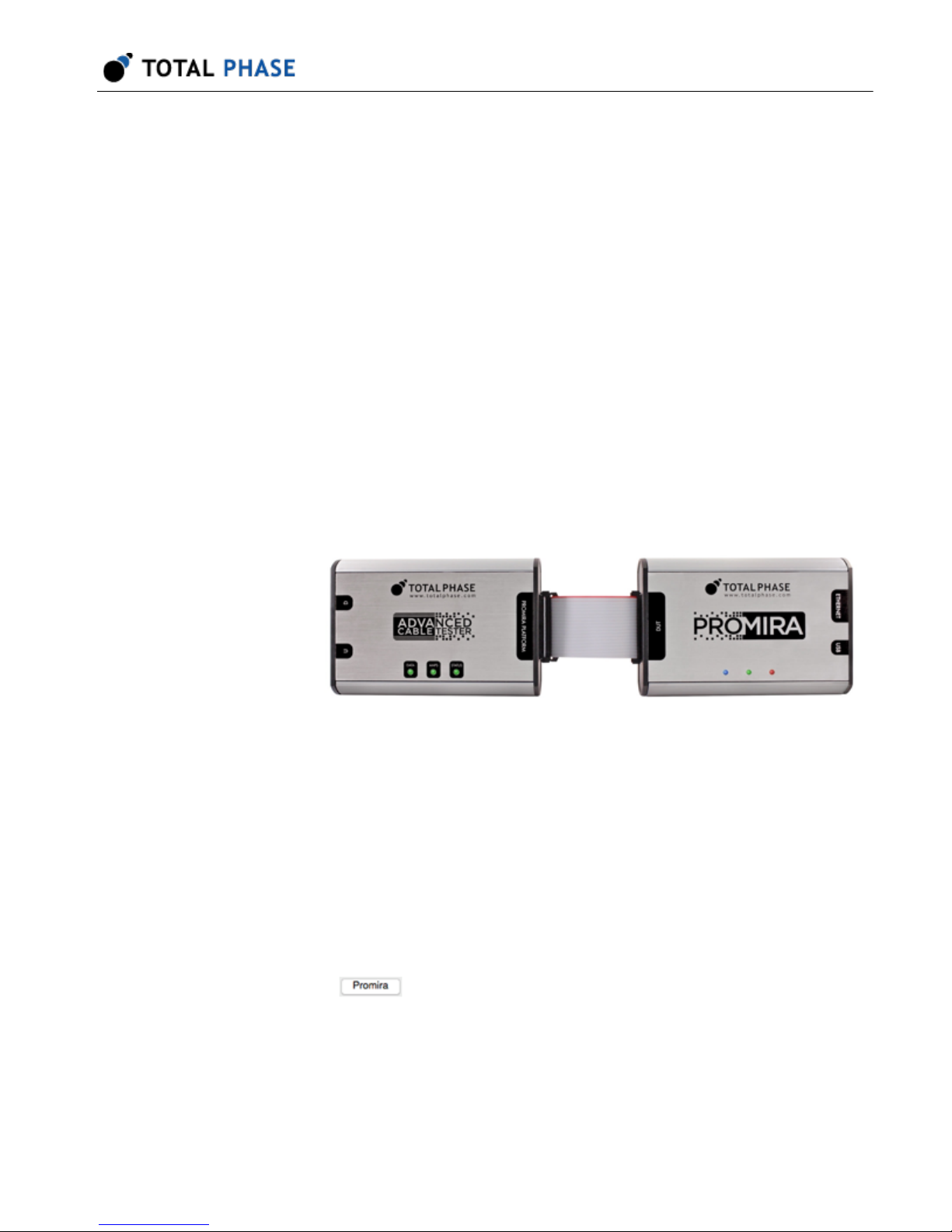
levels use the Advanced Cable Tester Hardware, pictured below.
This document describes the Advanced Cable Tester web software applications, the
Advanced Cable Tester Hardware and how to use both.
3

Advanced Cable Tester User Manual v1.13.001
Figure 1 : ACT Hardware
Figure 2 : ACT System
Primarily targeted at USB cables, the main hardware natively supports testing Type-C-toType-C cables. Adapter cards are available to enable testing cables that terminate in
USB 3.1 Standard-A, USB 3.1 Micro-B, and Lightning USB2.
Continuity testing checks all pins for continuity, preventing dangerous situations like
shorts of VBUS to data signals, VBUS/GND reversal, etc., which could damage devices.
DC Resistance ("DCR") and IR Drop testing confirms that each power pin (VBUS and
GND) is capable of carrying the required current to meet the applicable specification. For
Type-C cables, each power pin is individually measured, then the cable as a whole is
tested.
4

Advanced Cable Tester User Manual v1.13.001
E-Marker testing reads the data from all E-Markers present on the cable, then validates
the advertised data and power capabilities against the actual measured parameters of
the cable. Additionally, the values of fields such as Vendor ID, Product ID, Test ID,
firmware and hardware versions can be specified by the operator, for easy pass/fail
determination of cables through a QA process.
The Advanced Cable Tester provides an easy-to-use web interface that allows for remote
operation and logging. Using the Promira platform's connectivity, the Advanced Cable
Tester can be operated over USB or over Ethernet. The Advanced Cable Tester can also
be configured to operate in a stand-alone mode that does not require a host PC. The
LEDs on the device provide straight-forward pass/fail information for the qualification of
cables without the need for the graphical interface.
5
Advanced Cable Tester User Manual v1.13.001
2 Device Specifications
2.1 Hardware Connectors and LED Indicators
Table 1 : Connector Description
Connector Purpose
Promira platform Connects to Promira platform via included 40mm 34pin ribbon cable
U Type-C connector for connecting to one plug of the cable under test.
Typically configured as the functional Source when testing Type-C cables.
D Similar function to the U connector, but typically configured as the
functional Sink when testing Type-C cables.
Advanced
Cable Tester
LEDs
Table 2 : LED Function and Description
LED Purpose and Meaning
Data Indicates data signal integrity is within expected values. Only valid for
the Advanced Cable Tester - Level 2 Application.
Off: Test not performed (Level 1 application)
Green: Indicates that signal integrity passed.
Red: Indicates a signal integrity or other data line failure.
Amps Indicates power-related test result of the cable.
Green: Cable shows no power-related failures, and can carry its
specified current.
Red: Power-related failure, such as shorts/opens, out-of-spec IR
Drop/DCR, etc.
Status Off: Not ready or Test in Progress
Green: Test completed and passed
Red: Test completed and failed
Blue flashing: Idle or waiting for cable attachment
Note While idle or waiting for cable, the Data or Amps LEDs will illuminate
green to indicate an adapter is present, blue to indicate that a USB
Type C plug has been detected, or blue-green to indicate that a cable
has been detected in the attached adapter, corresponding to the
"D"and "U" receptacles.
6

Promira LEDs Left Blank: Normal state
Middle Blue flashing: Test in progress
Off: Idle
Right Green: Advanced Cable Tester application running
Blue: No application running (Promira idle)
2.2 Software Specifications
• Test Profiles: Held in non-volatile storage on the Promira platform
• Test Results: Up to 1000 sets of results are kept in a circular buffer in RAM. Test
results are cleared upon power cycle.
Advanced Cable Tester User Manual v1.13.001
2.3 Physical Specifications
• DC Characteristics: Power Consumption: 900mA @ 5 V with Promira platform
• Dimensions: W x D x L: 77.5 x 29.2 x 115.6 mm (3.05 x 1.15 x 4.55 in)
• Weight: 125 g (4.41 oz)
• Operating Temperature: 10°35° C (50°95° F) non-condensing
7

Advanced Cable Tester User Manual v1.13.001
3 Promira Serial Platform Overview
The Promira Serial Platform is a multi-purpose test platform. Total Phase separately
licenses many other applications for other types of test and development. This includes
Host Adapter and Analysis applications for I2C, SPI, eSPI, etc. The Advanced Cable
Tester Applications are just a few possibilities for the platform. Details about the Promira
Serial Platform are included in the separate Promira Serial Platform System User Manual
(https://www.totalphase.com/support/articles/204227283). A brief overview of essential
usage details is included here.
3.1 Basic Connectivity
The basic interface to the Promira Serial Platform is via USB or Ethernet. In either case,
the USB micro-B interface is used for power (see below). Communication between the
end user platform and the Promira is via TCP/IP over Ethernet-over-USB or via TCP/IP
over Ethernet. The Ethernet over USB connection is established using the RNDIS or
ECM protocol. In this case, the Promira will act as a DHCP server, provide an IP address
t your PC/Mac in the 10.0.0.0/24 range.
When using the physical Ethernet connection, the Promira platform can use a static IP
address or act as a DHCP client, depending on network requirements. It is most
convenient to use the Promira Utility (https://www.totalphase.com/products/promiraupdate-utility) software to discover the address that was assigned. The utility software
can connect to the Promira via USB or Ethernet connection. The Promira Utility software
can also be used to configure a static IP address for the Promria platform (and therefore
the Advanced Cable Tester).
3.2 Powering the Promira and ACT
In the case where an Ethernet connection is used, it is necessary to power the Promira
platform (and the Advanced Cable Tester) via a USB power adapter with a Micro-B
cable. It is essential that this is a high-quality power supply, capable of supplying a
minimum of 5V at 1A of current, and with all relevant safety certifications. If a power
adapter does not provide enough power, the Promira platform and the Advanced Cable
Tester Hardware may not have enough power to operate properly and thus cannot
ensure valid testing.
After the Promira platform is configured, the Advaned Cable Tester Application is simply
accessed via HTTP from an HTML5-compatible web browser. This could be a mobile
8

phone, tablet, or most often a PC. Please consult the Quick Start Guide at the end of this
manual or on our website at Quick Start Guide (http://www.totalphase.com/support/
articles/235050988).
3.3 Update Process
In order to update your Promira databases properly, you must follow the below procedure
to backup any custom profiles you have created, reset the profile database, and then
restore any custom profiles.
The full update sequence is:
1. Start the Promira Utility (v1.35 or later available at Download) and use it put the
Promira in firmware update mode:
a. Click the Promira button.
Advanced Cable Tester User Manual v1.13.001
b. Find your Promira device in the list. If it doesnt appear yet, wait a little while
for it to finish booting and enumerating, then click the button to refresh the
list.
c. Select the Promira which was found, and click OK.
d. Click the Update License/Firmware button.
2. Copy the new firmware (.pmu file) to the Promiras disk. Typically your PC will
notify you that a new disk has been detected, and give you the option to browse it.
You may need to manually navigate to it using Finder or Explorer.
3. Eject the USB disk
4. Power-cycle the Promira the firmware will be automatically updated, which will
take about a minute to complete, during which time the LEDs will blink blue.
5. Wait for the right-most LED to illuminate green, then login to the Advanced Cable
Tester.
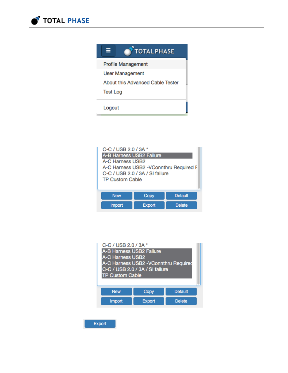
6. Open the "Profile Management" screen.
9
Advanced Cable Tester User Manual v1.13.001
7. Select your first custom profile. (Standard profiles are marked with a *; custom
profiles are not marked).
8. Hold down the Shift key on your keyboard and click on the last custom profile. (Be
sure youve scrolled to the end of the listbox).
9.
Click Export and a <filename>.json file will be downloaded to your
computer, make sure to save this.
10
Advanced Cable Tester User Manual v1.13.001
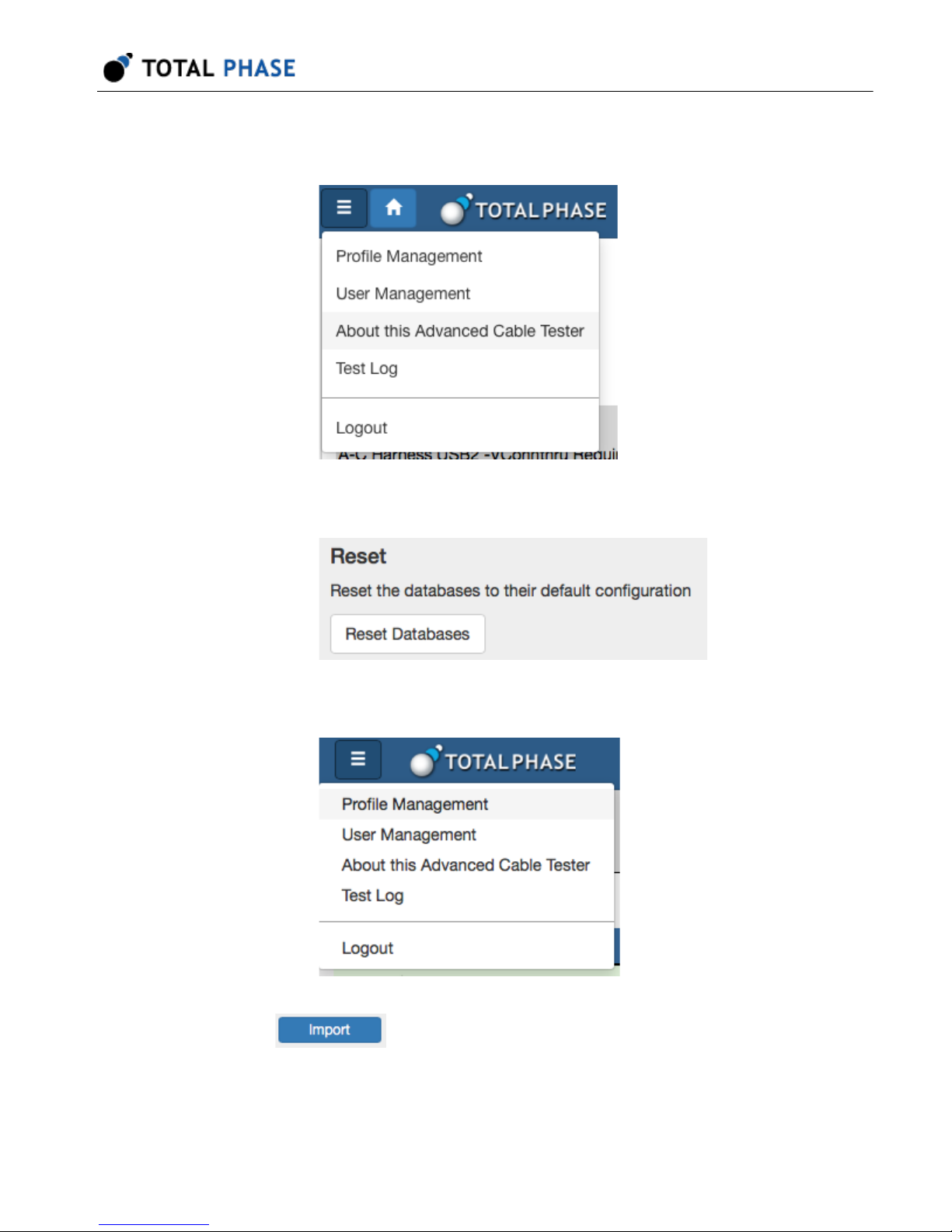
10. Open the About this Advanced Cable Tester screen., and click Reset Databases.
11. Click Reset Databases.
12. Return to the Profile Management screen.
13.
Click Import and re-import your saved custom profiles.
11

Advanced Cable Tester User Manual v1.13.001
4 User Interface Overview
The Advanced Cable Tester application is accessed via an HTML5 web browser,
connecting to the server application hosted on the Promira platform.
Features:
• Multi-user:
Advanced Cable Tester.
• Role-level access:
features.
• Responsive design:
tablets, and PCs.
• Preset test profiles:
• Custom test profiles:
configurations.
• Batch test mode:
insertion.
• Continuous test mode:
• Auto-start:
needing to start a test manually through the web interface.
Multiple users can simultaneously access, view, and control the
Different roles are available to limit access to the various
Single web interface is compatible with mobile browsers,
Standard test profiles are provided for common cable types.
Test profiles can be customized for specific test parameter
Capable of high-volume testing that auto-starts on cable
Includes single cable burn-in testing.
Advanced Cable Tester is ready for testing after power-up without
• Headless mode:
host device.
• Test profiles:
share between devices.
• Test results:
to 1000 sets of results can be kept. The test results are stored in a circular buffer.
Advanced Cable Tester can operate without a connection to a
stored on the device. Test profiles can be imported and exported to
stored in volatile memory and are cleared if the power is cycled. Up
12

If the results storage is full, then the oldest result set is automatically cleared to
make room for the new test result set.
4.1 Main User Interface
The main user interface displays two general sections: The Control section to configure
the Advanced Cable Tester, control the active test profile, and initiate testing. The
Results section which displays an overview of any available test reports, in addition to
allowing you to manage the individual reports.
Advanced Cable Tester User Manual v1.13.001
The Control section elements are:
*Stack* (Menu): This drop-down menu provides quick access to the various
management features of the Advanced Cable Tester Application: Profile
management, User Management, Device Information, Test Log, and Logout.
Which features are available will depend on the user's role.
Profile: The Profile menu provides a list of all cable profiles available on the
Advanced Cable Tester. When the page is first loaded, the default profile is
automatically selected.
Figure 3 : Main User Interface
13

Advanced Cable Tester User Manual v1.13.001
Batch: Batch mode is a special testing mode, which only requires the user
to click Start once to test a number of cables. Once started, the Advanced
Cable Tester will remain active and test cables as they are inserted. The
pass/fail status of the cable will be indicated by the LEDs on the Advanced
Cable Tester Hardware until the cable is unplugged. The test results will be
stored on the device and can be retrieved through the web interface.
Continuous: Continuous mode is a special testing mode which will
continuously run tests on a single cable until stopped, with a 500 ms delay
between test runs. This test mode is particularly useful for burn-in or
environmental testing of cables.
Start: Click to start a test, using the currently selected profile.
The Results section provides a list of the test results available on the Advanced Cable
Tester, and a high-level summary of the test outcomes. Clicking on any result will take
the user to the detailed test results view. If there are more than 10 reports available, then
use the and buttons to navigate to the previous or next page, and the and
buttons to go to the first or last pages. Additionally, it is possible to download and remove
test results by selecting them in the list and clicking on the (download) or (delete
selected) buttons. The summary test results shown in the current on-screen list can be
printed by clicking on the (print) button. Finally, all stored test results can be
downloaded by clicking the (download) button, or deleted by clicking the (delete all)
button.
4.2 Test Profiles and Profile Configuration
The Advanced Cable Tester includes an Auto-Detect profile, several preset Type-C
profiles, and the ability to create custom profiles. The preset profiles [marked with an
* (asterisk)] cannot be modified or deleted; they can be copied and exported.
14
Advanced Cable Tester User Manual v1.13.001
15

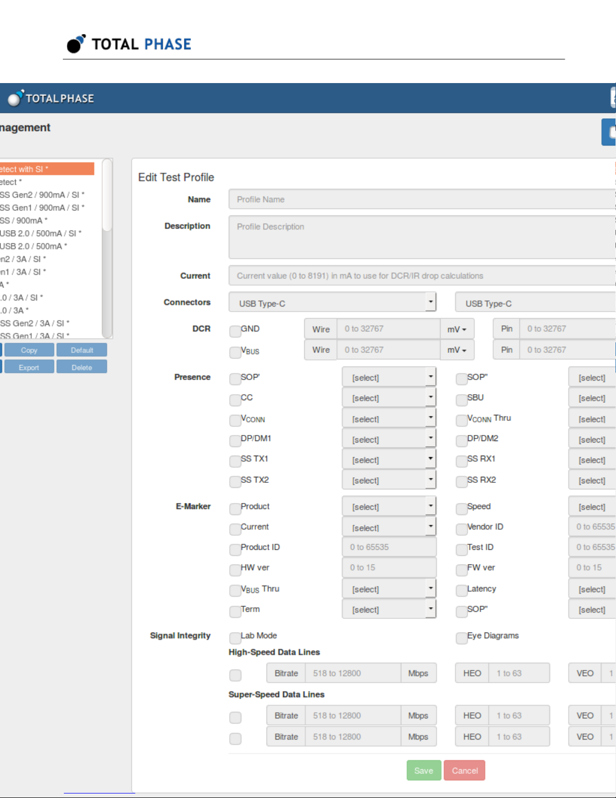
Figure 4 : Profile Management Page
4.3 Default Profiles
Advanced Cable Tester User Manual v1.13.001
There are several preset profiles. All profiles
are provided in both a "with SI" form, valid only for the Advanced Cable Tester - Level 2
Application, which performs signal integrity testing; as well as a simple version, valid for
both application levels, which does not perform signal integrity testing.
C-C Auto-Detect:
Marker presence and advertisements, SuperSpeed pair presence, and test accordingly.
Cable is tested only for spec compliance, within parameters that are tested by the
Advanced Cable Tester. With or without SI.
C-C SS Gen 2 – 5A: Test a Type-C-to-Type-C cable, capable of USB 3.1 Gen 2, and 5A
current.
C-C SS Gen 2 – 3A: Test a Type-C-to-Type-C cable, capable of USB 3.1 Gen 2, and 3A
current. Note: If E-Marker indicates 5A, this test will fail.
C-C SS Gen 1 – 5A: Test a Type-C-to-Type-C cable, capable of USB 3.1 Gen 1, and 5A
current. Note: If E-Marker indicates USB 3.1 Gen 2, this test will fail.
Auto-Detect cable type, based on any inserted adapter cards, E-
16

Advanced Cable Tester User Manual v1.13.001
C-C SS Gen 1 – 3A: Test a Type-C-to-Type-C cable, capable of USB 3.1 Gen 1, and 3A
current. Note: If E-Marker indicates USB 3.1 Gen 2 or 5A, this test will fail.
C-C USB 2.0 – 5A: Test a Type-C-to-Type-C cable, capable of USB 2.0 only, and 5A
current. Note: If E-Marker indicates USB 3.1 is supported, or if any SuperSpeed wire
pairs are present, this test will fail.
C-C USB 2.0 – 3A: Test a Type-C-to-Type-C cable, capable of USB 2.0 only, and 3A
current. Note: An E-Marker is optional for this profile. If E-Marker is present and indicates
USB 3.1 is supported, or E-Marker indicates 5A is supported, or if any SuperSpeed wire
pairs are present, this test will fail.
A-µB SS Gen 2 – 900mA: Test a standard A-to-micro B cable, capable of USB 3.1 Gen
2, and 900mA current.
A-µB SS Gen 1 – 900mA: Test a standard A-to-micro B cable, capable of USB 3.1 Gen
1, and 900mA current.
A-µB USB 2.0 – 500mA: Test a standard A-to-micro B cable, capable of USB 2.0, and
500mA current.
A-C SS Gen 2 – 3A: Test a Type-C-to-standard A cable, capable of USB 3.1 Gen 2, and
3A current.
A-C SS Gen 1 – 3A: Test a Type-C-to-standard A cable, capable of USB 3.1 Gen 1, and
3A current.
A-C USB 2.0 – 3A: Test a Type-C-to-standard A cable, capable of USB 2.0, and 3A
current.
C-µB SS Gen 2 – 3A: Test a Type-C-to-micro-B cable, capable of USB 3.1 Gen 2, and
3A current.
C-µB SS Gen 1 – 3A: Test a Type-C-to-micro-B cable, capable of USB 3.1 Gen 1, and
3A current.
C-µB USB 2.0 – 3A: Test a Type-C-to-micro-B cable, capable of USB 2.0, and 3A
current.
A-Lightning USB2: Test a USB A-to-Lightning cable, per MFi specifications.
17

Advanced Cable Tester User Manual v1.13.001
4.4 Profile Management Actions
When a profile is selected in the list, its settings are automatically loaded. Changes must
be saved by clicking the Save button at the bottom. Selecting another profile before
clicking the Save button will result in changes being lost.
The method for selecting multiple profiles for Download or Delete is browser-dependent,
but typically on Windows/Linux a range is selected by holding down Shift before clicking
on the second extent of the range, or by holding Control and clicking each individual
item; or on Mac OS X using Shift to select a range, and Command to select individual
items.
Create a new profile with blank fields.
New:
Copy: Create a copy of the currently selected profile. Use this to clone one
of the preset profiles, to create your own derivative.
Export: Export the selected profile as a JSON file. Multiple profiles can be
exported at once.
Delete: Delete the selected profile, after displaying a confirmation dialog.
Multiple profiles can be deleted at once.
Default: Set the selected profile as the default, automatically selected when
the application starts.
Import: Import a previously Exported profile(s) from a JSON file.
4.5 Profile Options
Name: This is the profile name, shown in the list of profiles. This will be displayed in the
test results.
Description: Verbose text describing the profile purpose. This will be displayed in the
test results and is a useful place to put descriptive information for users of the Advanced
Cable Tester and consumers of the test reports.
Current: Current value in milliAmps to use for DCR/IR drop calculations. When
computing the IR drop for VBUS/GND, it's necessary to factor in the current. Depending
on the cable type, a default will be used: 3000mA for unmarked Type-C, 3000mA or
18

Advanced Cable Tester User Manual v1.13.001
5000mA for E-Marked Type-C, 900mA for USB 3.1 cables terminating in an A or B
connector, and 500mA for USB 2.0 cables terminating in an A or B connector.
Connectors: This section has three drop-down selections for choosing the connectors
on the cable to be tested. No particular order is required for the selection as the ACT
automatically verifies that the selected connectors are available on the two ports of the
ACT. For example, if you select Type-C and Standard A, the ACT will verify that one and
only one Standard A Adapter is inserted into the ACT when the test begins execution. If
the ACT configuration does not match the selection at the start of a test, the test will
abort and the message "Invalid Profile" will be presented in the results summary.
This configures the parameters for the DC resistance (DCR) measurement for the
DCR:
cable, on the GND and VBUS lines. Both follow a similar pattern: If the checkbox is
selected, then the parameter is validated against measured values; if not selected, then
the results are reported but will not cause a failure.
GND / Wire: Maximum resistance or IR drop for the GND wire through the
cable. If units are set to mV then this is taken as Maximum IR drop; if units
are set to "mOh", then this is taken as Maximum DC resistance in milliohms.
GND / Pin: Maximum DC resistance for any GND pin, measured between
the Advanced Cable Tester and the paddle card, in milliohms.
VBUS / Wire: Maximum resistance or IR drop for the VBUS wire through the
cable. If units are set to mV then this is taken as Maximum IR drop; If units
are set to "mOhm", then this is taken as Maximum DC resistance in
milliohms.
VBUS / Pin: Maximum DC resistance for any VBUS pin, measured between
the ACT and the paddle card, in milliohms.
Presence: All items in this section follow a common pattern: If Required is checked, then
the items presence must match the Presence option.
SOP' & SOP'': Checks for presence of a corresponding E-Marker in the
cable. Any present E-Marker must be valid, match cable parameters, etc.
CC: Presence of the CC wire through the USB cable. For Type-C cables,
this is a fundamental requirement; this test is recommended as Present /
Required for Type-C-to-Type-C cables.
SBU: Presence of SBU1/SBU2 wires through the cable. These two wires
are required for Full-Featured Type-C cables.
19

Advanced Cable Tester User Manual v1.13.001
VCONN: Presence of the VCONN pulldown in the cable plug.
VCONN Thru: Presence of the VCONN wire through the cable. A cable that
has this is not Type-C compliant. This test is recommended as Absent /
Required.
DP/DM1: Presence of the USB2 wire pair, also known as D+/D-. These
wires are required for all Type-C cables. This test is recommended as
Present / Required.
DP/DM2: Presence of a second USB2 wire pair, also known as D+/D-.
These wires are prohibited for Type-C cables. This test is recommended as
Absent / Required.
SS TX1 / SS TX2 / SS RX1 / SS RX2: Presence of each of the four
SuperSpeed wire pairs: SSTX1, SSTX2, SSRX1, SSRX2. These wire pairs
are required for Full-Featured Type-C cables.
E-Marker: This section defines E-Marker parameter validation. If an E-Marker is present
in the cable, then the identity VDOs are read, and compared to the parameters specified
here. If the checkbox for a given item is checked, then the associated parameter must
match.
Product: Product type as specified in the ID Header VDO. Can be either
Passive Cable or Active Cable.
Speed: USB SuperSpeed Signaling Support as specified in the Cable VDO.
Can be USB 2.0 only, USB 3.1 Gen 1, or USB 3.1 Gen 1 and Gen 2.
Current: VBUS Current Handling Capability as specified in the Cable VDO.
Can be either 3A or 5A.
Vendor ID: USB Vendor ID as specified in the ID Header VDO.
Vendor Name: Vendor Name as specified in the USB.org and the linux.org
vendor lists.
Product ID: USB Product ID as specified in the Product VDO.
Test ID: USB Test ID (XID) as specified in the Cert Stat VDO.
HW Ver: Hardware Version as specified in the Cable VDO.
FW Ver: Firmware Version as specified in the Cable VDO.
20

Advanced Cable Tester User Manual v1.13.001
VBUS Thru: VBUS Through Cable, either Yes or No, as specified in the
Cable VDO.
Latency: Cable Latency, as specified in the Cable VDO.
Term: Cable Termination, as specified in the Cable VDO.
SOP DP: True if the emitter indicates an SOP'' controller is present, as
specified in the Cable VDO.
Signal Integrity: Parameters for signal integrity testing. These can be configured when
using the Advanced Cable Tester - Level 1 Application, but tests can only be run when
using the Advanced Cable Tester - Level 2 Application.
Lab Mode: When Lab mode is not enabled, the Advanced Cable Tester will
test for data reception only where reception expected, which results in faster
test times. When lab mode is enabled, the Advanced Cable Tester will test
signal integrity on all possible combinations of wires. If cable is mis-wired,
additional debug information may be available by checking this box.
Eye Diagrams: Enables capture and storage of the eye diagram data.
For each test option, Frequency controls at what rate to test. Test frequencies can be
selected between 518Mbps and 12Gbps. Not all test frequencies are available, if an
unavailable frequency is selected, the next highest available rate (or the maximum) will
automatically be chosen. The actual frequency used in signal integrity testing will be
returned in the results.
HEO and VEO set the minimum horizontal (HEO) and vertical (VEO) eye openings. Both
are specified only in internal units. It is recommended to start with one of the standard
profiles, and then fine-tune this by loosening (lowering) or tightening (raising) the value
as necessary.
High-Speed Data Lines: If checked, enables signal integrity analysis of the
USB2 DP/DM wire pair at the specified rate, with HEO and VEO validation
as specified.
21

Advanced Cable Tester User Manual v1.13.001
SuperSpeed Data Lines: If checked, enables signal integrity analysis of all
four SuperSpeed USB wire pairs at the specified rate, with HEO and VEO
validation as specified.
4.6 About This Advanced Cable Tester
This page describes the status of the Advanced Cable Tester and the associated
adapters (if installed). Additionally, this page provides a support utility and the "Reset
Databases" function for the ACT.
22

5 Test Specification
5.1 Test Coverage
The Advanced Cable Tester contains several types of analysis circuitry for testing the
different types of pins. With the exception of the lower-speed USB2 pins, a given pin type
is not tested by multiple analysis circuits. The tests have been carefully selected to
provide test coverage, while not increasing system cost of impacting accuracy.
Pin Groups
VBUS, GND: Tested using power pin tester.
CC, VCONN: Tested using a Type-C port controller.
Advanced Cable Tester User Manual v1.13.001
SSTX1, SSTX2, SSRX1, SSRX2: Tested using signal integrity circuit.
SBU1, SBU2, SHIELD: Tested using simple digital testing.
USB2 D+/D- pair: Tested using both digital tester and signal integrity circuit.
5.2 Test Sequence
The Advanced Cable Tester uses multiple phases to test the cables that are put under
test. The phases are generally measurement of the various cable parameters followed by
evaluation of the results for pass/fail criteria established by the selected profile and the
specifications of the USB Type-C Specification. The first phase is a safety test stage
where the cable is evaluated for shorts and mis-wires that are deemed to be safety
issues; the second phase measures all the parameters of the cable; and the final phase
takes all of the measured parameters and evaluates them against the requirements for
the cable under test. At the completion of the third phase, the web interface is updated
with the result and the information is available for further use by the end-user.
5.2.1 Test Phases
Test Phase 1
1. The first phase encompasses the Safety Test part of the test sequence. The
following items are checked during this phase.
23

Advanced Cable Tester User Manual v1.13.001
2. VBus to Ground Short
3. CC/VCONN to Ground Short
4. VBus to CC/VCONN Short
Test Phase 2
1. Shorts between all other pins
2. Continuity of defined and present pins
3. Mis-wires of defined and present pins
4. DC resistance of each of the Ground pins at both the "U" and "D" side of the cable
5. Total DC resistance of the Ground connection through the cable
6. DC resistance of each of the VBus pins at both the "U" and "D" side of the cable
7. Total DC resistance of the VBus connection through the cable
8. E-Marker detection and read out
a. From the "U" side of the cable (SOP' and SOP'')
b. From the "D" side of the cable (SOP' and SOP'')
9. Differentiate Pair continuity check
10. (Optional) Signal Integrity measurement
Test Phase 3
1. Compare the results from the above testing with the requirements of the profile
used and USB Type-C specifications.
2. Set the LEDs on the Advanced Cable Tester device per the pass/fail results.
24

3. Report to the web browser the results of the test.
5.3 Detailed Test information
5.3.1 DCR Resistance Tests
The Advanced Cable Tester utilizes a small current to measure the DC resistance of the
various parts of the cable. The individual pin test relies upon the fact that each end of the
cable has at least two of the four defined pins used for each of VBus or Ground. The
total cable DC resistance test relies on the presence of at least one good pin connection
on each end of the cable for the VBus and the Ground connection. If there are not
sufficient connections for the above tests, the Advanced Cable Tester reports back "no
connection" in the test results. It will report back as much information as it can discern
from the available connections.
NOTE: The Advanced Cable Tester does not use the maximum specificed current per
the USB Type-C Specification for the levels of 1.5 A, 3 A, or 5 A for legacy to Type-C or
Type-C to Type-C cables.
Advanced Cable Tester User Manual v1.13.001
5.3.2 Signal Integrity
Each requested test (HS USB and however many SS USB tests are specified) are
performed sequentially by iterating through the specified test rates. The default cases for
USB cables are 500 MBps (HS), 5 GBps, and 10 GBps (SS). The user can set the test
rates between 518 MBps and 12.8 GBps for both types of wires via the interface. If a test
is requested on a particular pair that does not support or is missing the correct
connection, the tester will try multiple times to look for a transmitted signal. If no lock of
the transmitted signal is received this process will slow down the overall test time. There
are two modes for operation of the signal integrity test. The "Lab Mode" switch enables/
disables the ability to look at all possible combinations for the SS pair rourting. It does
not affect the HS pair test. When disabled (default) the device only looks for the signals
at the USB Type-C specification locations (i.e., U end TX1, at D end RX1 or RX2
depending on cable orientation). If it is enabled it will look at all possible locations. The
results are returned as unitless measures HEO and VEO. The HEO is the Horizontal Eye
opening, and is a value from 0 to 63 with each unit representing 1/64 of the UI. The VEO
is the Vertical Eye opening, which is a value from 0 to 150 representing the vertical
opening of the recovered eye diagram. Each of these values re measured at the
respective horizontal and vertical centers of the UI. The HEO and the VEO are the
values used for pass/fail criteria.
25

Advanced Cable Tester User Manual v1.13.001
Eye diagrams are the complete UI results for each test. They are returned in the results
page for visual inspection but not used for pass/fail criteria.
5.3.3 Digital Pins
For the digital pins, which are defined as: SBU1, SBU2, DP1/DM1, and DP2/DM2 a
simple continuity test is used to verify presence or absence. This test will fail if the lines
are AC coupled between the Up and the Down port of the ACT. The test consists of
applying a voltage at one end of the cable and measuring the incoming signal at the far
end of the cable. The inputs are weakly pulled to the rail to prevent any false readings
from a floating conductor. (NOTE: The DP/DM pairs are also tested with high-speed
signal when the Signal Integrity option is purchased.)
5.3.4 E-Marker
The E-marker reading is achieved by sending a USB Power Delivery compliant query to
the cable when VConn is supplied. The ACT sends a SOP' and SOP'' message from
both the Up and the Down ports so as to verify presence of any content from both ends
of the cable. In the case of a Type-C to Legacy cable, the messages are only sent from
the Type-C end. All retrieved data from the cable is displayed in the results page. The
read of the CC is not dependent on Ra presence.
5.3.5 Shield
The shield of the cable is tested in different ways depending on the type of cable under
test. For a cable a simple detection first determines if the shield is connected to ground
at either end of the cable. If it is, no further testing is undertaken as it is indiscernable
from the ground circuits. If the shield is not connected to the cable ground, the shield
continuity is checked with a simple continuity test as used above for the digital pins.
26
Advanced Cable Tester User Manual v1.13.001
6 Appendix A: Quick Start Guide
6.1 Introduction
Promira™ Serial Platform with Advanced Cable Tester application is used to test next
generation USB Type-C™ cables. This article will get you up and testing USB Type-C
cables using a USB connection, the Promira Utility, and a web browser.
6.2 Setting up the Promira™ Serial Platform with Advanced
Cable Tester application
1. Connect the Advanced Cable Tester Hardware to the Promira platform, using the
34-Pin: 34-Pin Header Cable 40mm as shown below.
2. Connect the Promira platform to your PC using a USB Standard-A to Micro-B
cable.
3. Follow the instructions in Section 5.2 – Connectivity of the Promira platform
system user manual to configure Ethernet over USB interface.
4. Download and unzip the latest version of Promira Utility for your OS. (?)
5. Start the Promira Utility and use it to connect to your Promira by clicking the
Promira button in the upper-left corner of the utility window.
a.
Click the
b. Find your Promira device in the list.
Promira button.
27

Advanced Cable Tester User Manual v1.13.001
If it doesn't appear yet, wait a little while for it to finish booting and
enumerating, then click the button to refresh the list.
c. Select the Promira device which was found, and click OK.
6. In order to start the Advanced Cable Tester application on the Promira platform
you must enable it as the "Auto Start App:" by clicking on the pulldown.
a. Choose "com.totalphase.promact_cab" in the list, and click Apply.
b. Note the IP address shown in the window. This is the address of the device
that you will need below in the process.
c. Power-cycle the Promira by unplugging the USB cable, and plugging it back
in.
d. Wait for the Promira platform's right LED to go from RED to BLUE and finally
to GREEN.
6.3 Testing USB Type-C™ Cables
1. Open a web browser, and navigate to http://<ip-address-from-above>/
For example, assuming the IP shown was 10.1.4.233, then the URL would be
http://10.1.4.233/
28

Advanced Cable Tester User Manual v1.13.001
2. Login using the default credentials:
Username: admin
Password: ChangeMe
3. Insert a USB Type-C cable into the "U" and "D" ports on the Advanced Cable
Tester Hardware.
4. Click "Start Test"
5. The cable will be tested, and results summary will be shown on the screen.
6. To see the detailed results, click on the results line that you are interested in
viewing.
29

7 Legal / Contact
7.1 Disclaimer
All of the software and documentation provided in this manual, is copyright Total Phase,
Inc. ("Total Phase"). License is granted to the user to freely use and distribute the
software and documentation in complete and unaltered form, provided that the purpose
is to use or evaluate Total Phase products. Distribution rights do not include public
posting or mirroring on Internet websites. Only a link to the Total Phase download area
can be provided on such public websites.
Total Phase shall in no event be liable to any party for direct, indirect, special, general,
incidental or consequential damages arising from the use of its site, the software or
documentation downloaded from its site, or any derivative works thereof, even if Total
Phase or distributors have been advised of the possibility of such damage. The software,
its documentation, and any derivative works is provided on an "as-is" basis, and thus
comes with absolutely no warranty, either express or implied. This disclaimer includes,
but is not limited to, implied warranties of merchantability, fitness for any particular
purpose, and non-infringement. Total Phase and distributors have no obligation to
provide maintenance, support, or updates.
Advanced Cable Tester User Manual v1.13.001
Information in this document is subject to change without notice and should not be
construed as a commitment by Total Phase. While the information contained herein is
believed to be accurate, Total Phase assumes no responsibility for any errors and/or
omissions that may appear in this document.
7.2 Life Support Equipment Policy
Total Phase products are not authorized for use in life support devices or systems. Life
support devices or systems include, but are not limited to, surgical implants, medical
systems, and other safety-critical systems in which failure of a Total Phase product could
cause personal injury or loss of life. Should a Total Phase product be used in such an
unauthorized manner, Buyer agrees to indemnify and hold harmless Total Phase, its
officers, employees, affiliates, and distributors from any and all claims arising from such
30

use, even if such claim alleges that Total Phase was negligent in the design or
manufacture of its product.
7.3 Contact Information
Total Phase can be found on the Internet at http://www.totalphase.com/. If you have
support-related questions, please go to the Total Phase support page at http://
www.totalphase.com/support/. For sales inquiries, please contact sales@totalphase.com
.
Advanced Cable Tester User Manual v1.13.001
©2003-2018 Total Phase, Inc.
All rights reserved.
31
 Loading...