

Total Mobile Audio T2-320.4 Owner's Manual

Thank you for purchasing a Total Mobile Audio amplifier for
your automotive sound system.
Your amplifier has been designed and manufactured to exacting
standards in order to ensure years of musical enjoyment in your vehicle.
For maximum performance and extended warranty
coverage, we highly recommend that you have your new amplifier
installed by an authorized Total Mobile Audio dealer. Your authorized
dealer has the training, expertise and installation equipment to ensure
optimum performance from this product. Should you
decide to install the amplifier yourself, please take the time
to read this manual thoroughly so as to familiarize yourself
with its installation requirements and setup procedures.
If you have any questions regarding the instructions in this
manual or any aspect of your amplifier’s operation, please contact your
authorized Total Mobile Audio dealer for assistance. If you need further
assistance, please call our Technical Support Department
at (954) 443-1100 during business hours.
OWNER’S MANUAL
320W 4-Channel, Full-Range Amplifier
2 Total Mobile Audio
3
PLANNING YOUR INSTALLATION
It is important that you take the time to read
this m anual and t hat you plan out your
insta llation caref ully. The followi ng are some
considerat ions that you must t ake into account
when plan ning your ins tallation.
Cooling Efficiency Consid erations:
The outer shell of your TMA amplifier is
designed to remove heat from the amplifier
circuitry. For optimum cooling performance, this
outer shell should be exposed to as large a volume
of air as possible. Enclosing the amplifier in a
small, poorly ventilated chamber can lead to
excessive heat build-up and degraded
performance. If an installation calls for an
enclosure around the amplifier, we recommend
that t his enclosure be ventilated with the aid
of a fan. In normal applications, fan-cooling
is not nece ssary.
Mounting t he amplifier upsi de down is
strongly discouraged.
If mounting the amplifier under a seat,
make su re there is at lea st 1 inch (2.5 c m) of
space above the amplif ier’s outer shel l to permit
proper coolin g.
Safety Considerations:
Your amplifier needs to be installed in a dry,
well-ventila ted environment a nd in a manner
which does not interfere with your vehicle’s safety
equipment (air bags, seat belt systems, ABS brake
systems, etc.). You should also take the time to
securely mount the amplifier so that it does not
come loose in the event of a collision or a sudden
jolt to the vehicle.
Stupid Mistakes to Avoid
• Check before drilling any holes in your vehicle
to make sure that you will not be drilling
throug h a gas tank , brake line, wiring har ness or
other v ital vehicle sys tem.
• Do not run system wiring outside or underneath
the vehic le. This is a n extremely da ngerous
practice which can result in severe damage to
your vehic le and person.
• Protect all system wires from sharp metal
edges and wear by carefully routing them,
tying them down and using grommets and
loom where appropriate .
• Do not mount the amplifier in the engine
compart ment, under the ve hicle, on the roof
or in a ny other area th at will exp ose the
amplifier circuitry to the elements.
PROTECT YOUR H EARING!
We value you as a long-term customer. For
that rea son, we urge you to pr actice restra int in
the oper ation of this produc t so as not to d amage
your hearing and that of others in your vehicle.
Studies have shown that cont inuous exposure to
high sound pressure levels can lead to permanent
(irrepara ble) hearing loss . This and a ll other
high-power a mplifiers ar e capable of producing
such hig h sound pressure le vels when connect ed
to a spea ker system. Plea se limit your continuous
exposu re to high volume le vels.
While driving, op erate your audio sy stem in
a manner that still allows you to hear necessary
noises to operate your vehicle safely (horns,
sirens, etc.).
SERIAL NUMBER
In the event that your amplifier requires
service or is ever stolen, you will need to have
a record of the product’s serial number. Please
take the time to enter that number in the space
provided be low. The serial nu mber can be fou nd
on the bottom panel of the amplifier and on the
amplifier packag ing.
Serial Number:
INSTALLATION APPLICATIONS
This amplifier is designed for operation in
vehicles with 12 volt, negative-ground electrical
systems. Use of this product in vehicles with
positive ground and/or voltages other than 12V
may result in damage to the product and will void
th e w arr ant y.
This product is not certified or approved for
use in aircraf t.
Do not att empt to “bridge” t he outputs of th is
amplif ier with the outputs of a second amplifier,
includin g an identical one.
HP | Off | LP
Filter Mode
High-Pass Low-Pass
Filter Frequency (Hz)
Filter Frequency (Hz)
Input Sens.
Input Sens.
CH 3&4
Input From
min maxmin max 60 1.2k
High-Pass
60 1.2k 40 150
Low-Pass
40 150
Off +12dB
High-Level InputsHigh-Level Inputs
Bass Boost
HP | Off | LP
Filter Mode
1&2 | 3&4
Off +12dB
Bass Boost
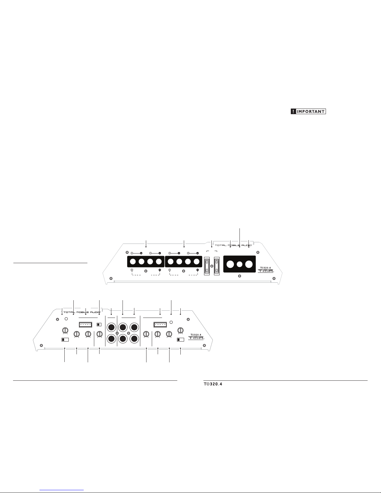
Channel 3 & 4 Controls
CH 1 (Left) CH 3 (Left)
Protect
Channel 1 & 2 Controls
Power
CH 2 (Right)
LEFT
RIGHT CH 4 (Right)
Pre-Outs Amplifier Inputs
a JL Audio® Company
Protection Status
Indicator
(pg. 11)
Low-Pass Filter
Frequency Control
(pg. 8)
Input Sensitivi ty
Control
(pg. 7)
Input Sensitivi ty
Control
(pg. 7)
Filter Mode
Selector
(pg. 8)
Filter Mode
Selector
(pg. 8)
Channel Input
Selector
(pg. 7)
Left & Right
Preamp Out put Jack s
(pg. 9)
High-Level
Input Jack
(pg. 6,7)
Power Status
Indicator
(pg. 11)
Bass Boost
Control
(pg. 9)
Bass Boost
Control
(pg. 9)
High Level
Input Jack
(pg. 6,7)
High-Pass Filter
Frequency Control
(pg. 8)
High-Pass Filter
Frequency Control
(pg. 8)
Low-Pass Filter
Frequency Control
(pg. 8)
CH 1 & CH 2
Preamp Input Jacks
(pg. 6)
CH 3 & CH 4
Preamp Input Jacks
(pg. 6)
Remote Turn-On
Connector
(pg. 6)
CH 1 & CH 2
Speaker Outputs
(pg. 9)
CH 3 & CH 4
Speaker Outputs
(pg. 9)
+12 V Power
Connector
(pg. 5)
Fuses
(pg. 5)
Chassis Ground
Connector
(pg. 5)
Made in China
CHANNEL 1 (L) CHANNEL 2 (R)
Bridged Bridged
CHANNEL 3 (L) CHANNEL 4 (R) FUSES + VDC
30A30A
Remote Ground
a JL Audio® Company
4 Total Mobile Audio
5
POWER CONNECTIONS
Before installing the amplifier, disconnect the
negative (ground) wire from the vehicle’s battery.
This will prevent accidental damage to the system,
the vehic le and your body during inst allation.
Remote Ground
a JL Audio® Company
The T2-320.4’s “+12 VD C” and “Ground”
connect ions are designed to accept 4 AWG power
wire. 4 AWG is a minimum power wire size for
this amplifier.
If you are installing the T2-320.4 with other
amplif iers and wish to use a single main power
wire, use 2 AWG or larger main power wire
(depending on the overall current demands of all
the amplifiers in the system). This 2 AWG or
larger power wire should terminate into a
distribution block mounted as close to the
amplifiers as possible and should connect to the
T2-320.4 with 4 AWG power wire.
Note: Smaller AWG numbers mean bigger wire
and vice-versa (1/0 AWG is the largest, 2 AWG is
smaller, then 4 AWG, then 8 AWG, etc.).
To connect the power and ground wires to the
amplifier, strip 1/2-inch (12 mm) of insulation
from each wire and insert the bare wire into the
the appropriate terminal block positions on the
T2-320.4. Use a Phillips screwdriver to secure the
wire via the screw on the top of each terminal.
The “GROU ND” connection should be made
using 4 AWG wire and should be kept as short
as possible, while accessing a solid piece of sheet
metal i n the vehicle. T he surface of t he sheet
metal s hould be sanded at the contact poi nt
to create a clean, metal-to-metal connection
between the chassis and the termination of
the ground wire. The use of a star washer to
lock down the connection is advisable.
Any wires run through metal barriers (such as
firewa lls), must be protec ted with a hi gh quality
insulat ing grommet to prevent damage to t he
insulation of the wire. Failure to do so may result
in a dangerous short circuit.
Many vehicles employ small (10 AWG -
6 AWG) wire to ground the battery to the
vehicle chassis and to connect the alternator’s
positive con nection to the bat tery. To prevent
voltage drops, these wires should be upgr aded
to 4 AWG when installing amplif ier systems
with ma in fuse rati ngs above 60A.
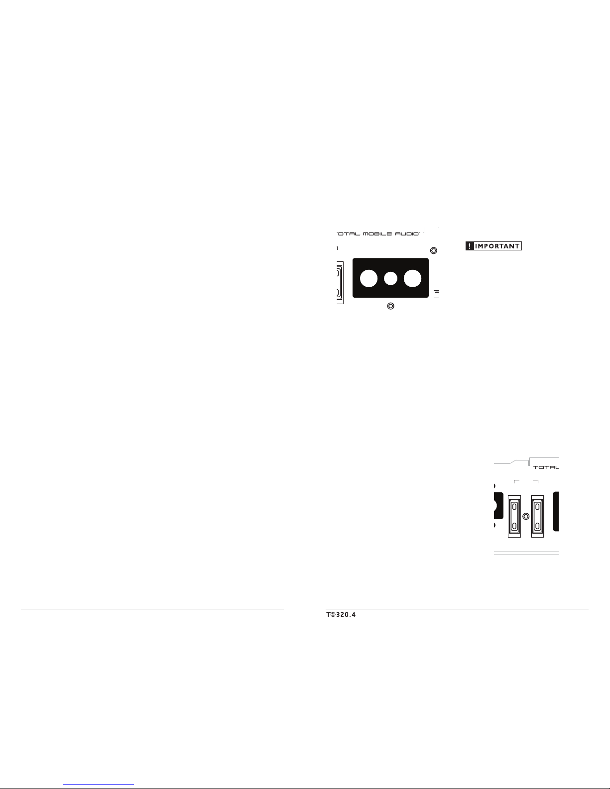
FUSE REQUIREMENTS
While the T2-320.4 has t wo 30A ATC fuses
on its power connection panel, these do nothing
to protect the vehicle from a dangerous short
circuit in the power wire. They only protect the
amplifier. It is absolutely vital that the main
power lead to the amplifier(s) in the system be
fused within 18 inche s (45 cm) of t he positive
battery post connection. The fuse value at each
power wire should be high enough for all of the
equipment being run from that power wire.
If only t he T2-320.4 is bei ng run from t hat power
wire, we recommend a 60A fuse be used. AFS or
MAX I-type fuse s are recommended .
30A30A
Remote Ground
a JL Audio® Company
PRODUCT DESCRIPTION
The Total Mobi le Audio T2-320.4 is a fou rchannel, full-range audio amplifier utilizing
Class B technology for a ll channels .
The T2-320.4 can be operated with a wide
variety of source units and system configurations.
For detai led specific ations, please re fer to
Appendix B (page 13).
TYPICAL INSTALLATION SEQUENCE
The following represents the sequence
for a ty pical amplif ier instal lation, using a n
after market source u nit or OEM Interfa ce
product. Additional steps and different
procedures may be required in some applications.
If you have a ny questions, ple ase contact your
authorized TMA dealer for assistance.
1) Disconnec t the negative b attery post
connection and secure the disconnected cable
to prevent accidental re-connection during
insta llation. This step is not optional.
2) Run 4 AWG power wire from the battery
location to the amplifier mounting location,
taking care to route it in such a way that it
will not be damaged and will not interfere
with ve hicle operation. Use 2 AWG or l arger
power wire and a power distribution block if
additiona l amplifiers are being ins talled wit h
the T2-32 0.4.
3) Connect p ower wire to the p ositive battery
post. Fuse the wire with an appropriate fuse
block (and con nectors) within 18 inches (45
cm) wire length of the positive battery post.
This fuse is essential to protect the vehicle.
Do not install the fuse until the power wire
has been securely connected to the amplifier.
4) Run signal cables and remote turn-on wire
from the source unit to t he final a mplifier
mounting location.
5) Run spea ker cables from the speaker s ystems
to the a mplifier mount ing location.
6) Find a good, solid metal grounding point
close to t he amplifier and connect t he
negative power wire to it usi ng appropriate
hardware. Use the same size power wire as the
wire con nected to the “+1 2VD C” connection
(minimum 4 AWG), no longer than 36 inches
(90 cm) from the amplifier to the ground
connection point. In some vehicles, it may be
necessary to upgrade the battery ground wire.
(See page 5 for important notice).
7)
Securel y mount the ampli fier using
appropriate hardware.
8) Connect the positive a nd negative power
wires t o the amplif ier.
9) Connect the remote turn-on wire
to the a mplifier.
10) Con nect the input ca bles to the ampl ifier.
11) Connect t he speaker cabl es to the ampli fier.
12) Carefully review the amplifier’s control
settings to make sure that they are set
according to the needs of the system.
13) Instal l the power wire fuse (60A for a
single T 2-320.4) and re connect the negat ive
battery post terminal.
14) Turn on the source un it at a low level
to double-check that the amplifier is
config ured correct ly. Resist t he temptation
to crank it up until you have verified the
control set tings.
15) Make necessary adjustments to the input
sensitivity controls to obtain the right
overall output and the de sired balance
in the system. See Appe ndix A (page 12)
for the recommended input sensitivity
setting method.
16) Enjoy the fruits of your labor with your
favorite music .
6 Total Mobile Audio
7
Make sure you observe correct polarity in
making the “High Level Input” connections.
Failure to do so will reduce bass and affect
stereo imaging.
The conne ctions for the “High Level Inputs” plug
wires a re as follows f rom left to r ight on the plug :
Channels 1&2 (FRONT)
White: Left Positive (+)
White/B lack: Left Ne gative (–)
Black: Common Ground (rarely used)*
Gray: R ight Positive (+)
Gray/Black : Right Negative (–)
Channels 3&4 (REAR or SUB)
Green: Le ft Positive (+)
Green/Bla ck: Left Negat ive (–)
Black: Common Ground (rarely used)*
Purple: Right Positive (+)
Purple/ Black: Right Negative (–)
*The only time you will use the Common Ground
connections is with some older (pre-1980’s) factory
systems or head units that ground their speakers to
chassis ground. To use these connections, ground
the black wires on the plugs to chassis ground and
only connect the Left and Right Positive plug wires
to the factory radio outputs.
“CH 3&4 Input From” Switch
If you wish to send four discrete channels of
input into the T2-320.4, simply use all four inputs
(Channels 1 & 2 and Channels 3 & 4) and set the
“CH 3&4 Input From” switch to “3&4”.
HP | Off | LP
Filter Mode
High-Pass Low-Pass
Filter Frequency (Hz)
Input Sens.
Input Sens.
CH 3&4
Input From
min maxmin max 60 1.2k
Off +12dB
High-Level InputsHigh-Level Inputs
Bass Boost
1&2 | 3&4
Channel 3 & 4 Controls
CH 1 (Left) CH 3 (Left)
Protect
CH 2 (Right)
LEFT
RIGHT CH 4 (Right)
Pre-Outs Amplifier Inputs
a JL Audio® Company
If you w ish to feed all four channels by using
only two channels of input , set the “CH 3&4
Input From” switch to “1&2” and use only the
inputs to c hannels 1 & 2.
INPUT SENSITIVITY CONTROLS
The control s labeled “Input Se ns.” located in
each “Chan nel Controls” section can be used
to match the source unit’s output voltage to the
input sta ge of each pair of amplifier ch annels
for max imum clean output . Rotating the control
clockwise will result in higher sensitivity (louder
for a given input voltage). Rotating the control
counter-clockwise will result in lower sensitivity
(quieter for a given input voltage.)
HP | Off | LP
Filter Mode
High-Pass Low-Pass
Filter Frequency (Hz)
Input Sens.
Input Sens.
CH 3&4
Input From
min maxmin max 60 1.2k
Off +12dB
High-Level InputsHigh-Level Inputs
Bass Boost
1&2 | 3&4
Channel 3 & 4 Controls
CH 1 (Left) CH 3 (Left)
Protect
CH 2 (Right)
LEFT
RIGHT CH 4 (Right)
Pre-Outs Amplifier Inputs
a JL Audio® Company
To properly set the amplifier for maximum
clean out put, please refer to Appendix A (page
12) in this manual. After using this procedure,
you can then adjust any or all “Input Sens .”
levels downward if this is required to achieve the
desired system balance.
Do not increase any “Input Sens.” setting for
any channel(s) of any amplifier in the system
beyond the maximum level established duri ng
the procedure outlined in Appendix A (page
12). Doing so will result in audible distortion
and possi ble speaker dam age.
TURNON LEAD
The T2-320.4 is turned on and off
using a conventional +12V remote turn-
on lead, typically controlled by the
source unit’s remote turn-on output.
Remote Ground
a JL Audio® Company
The a mplifier wi ll turn on whe n +12V i s
present at its “Remote” input and turn off when
+12V is switched off. If a source unit does not
have a ded icated remote tur n-on output, the
amplif ier’s turn-on lead c an be connecte d to +12V
via a s witch that deri ves power from an i gnitionswitched circuit.
18 AWG wire is more than adequate for
the remote turn-on connection. To connect
the remote turn-on wire to the amplifier, strip
1/2-inch (12 mm) of insulation from the wire
and ins ert it into the “Remote” receptacle on the
power connec tor. Tighten the conne ctor down
using a Phillips screwd river.
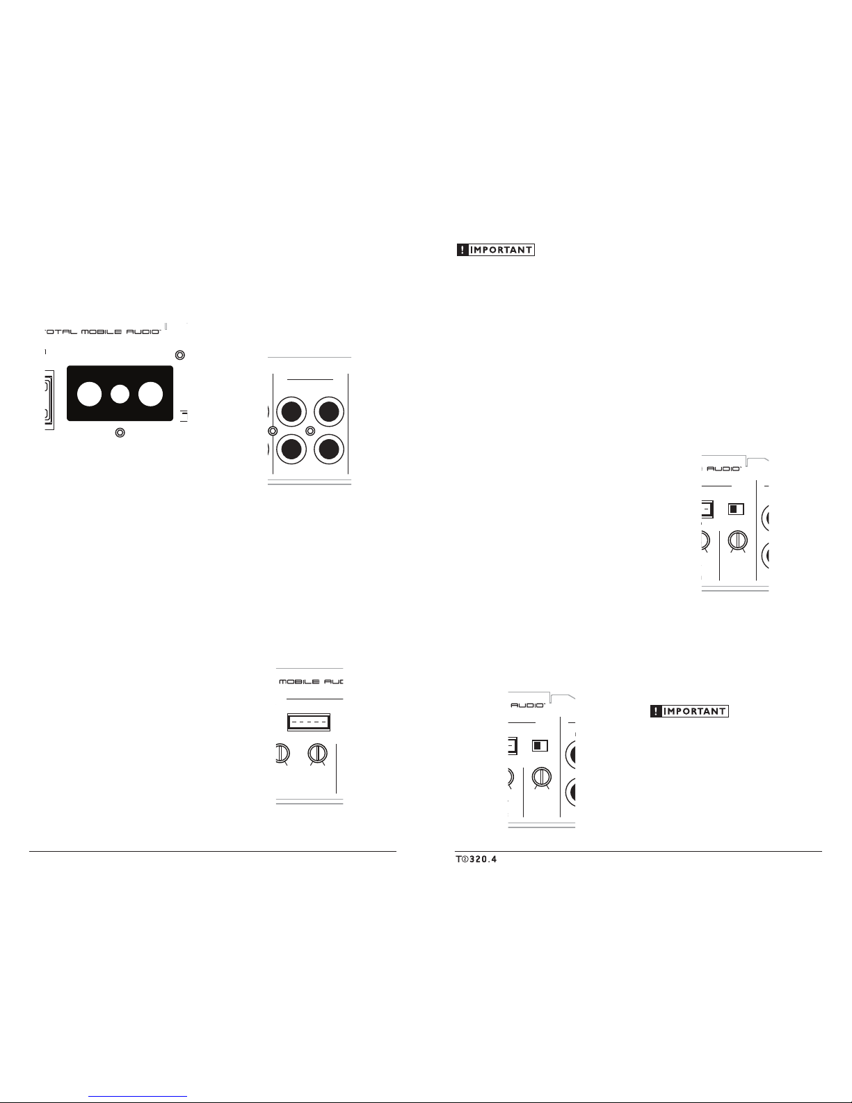
INPUT SECTIONS
The T2-320.4’s has two input sect ions: one for
Channel s 1&2 and another for Chan nels 3&4.
These input sections allows you to send signals to
the amplifier sections through the use of either
two or four inputs. Each input section offers
two input connection metho ds, one for highlevel (speaker level) signals and one for low-level
(preamp level) signals.
1) Low-Le vel Inputs: A standard left/
right pa ir of RCA typ e jacks in t he
“Amplifier Input s” section is used for
preamp level (low-level) signal input
on the T 2-320.4. T his is the prefer red
connect ion method whenever available.
HP | Off | LP
Filter Mode
High-Pass Low-Pass
Filter Frequency (Hz)
Input Sens.
min maxmin max 60 1.2k
Off +12dB
High-Level InputsHigh-Level Inputs
Bass Boost
Channel 3 & 4 Controls
CH 1 (Left) CH 3 (Left)
Protect
CH 2 (Right)
a JL Audio® Company
2) Hig h-Level Inputs: If your system does
not offer a preamp level signa l option, you
can connect speaker level signals directly to
the “Hig h-Level Inputs” connectors using
the suppl ied mating connec tors and wire
harnesses. Simply splice the appropriate
left/ri ght and positive/negat ive wires to the
included harnesses and plug the harness into
the “Hig h-Level Inputs” con nectors on the
amplif ier. The T2-320.4 wi ll attenuate th e highlevel sign als to make t hem compatible wit h its
input sta ges.
HP | Off | LP
Filter Mode
High-Pass Low-Pass
Filter Frequency (Hz)
Input Sens.
Input Sens.
CH 3&4
Input From
min maxmin max 60 1.2k
High-Pass
60 1.2k 40 150
Off +12dB
High-Level InputsHigh-Level Inputs
Bass Boost
1&2 | 3&4
Channel 3 & 4 Controls
CH 1 (Left) CH 3 (Left)
Protect
Channel 1 & 2 Controls
CH 2 (Right)
LEFT
RIGHT CH 4 (Right)
Pre-Outs Amplifier Inputs
a JL Audio® Company
 Loading...